Albatross AlbaCombi User manual

USER MANUAL
V1.0.5, Rev A
November 2014

AlbaCombi - Analog to NMEA 2000 Converter page 2/33
Table of Contents
PRODUCT OVERVIEW .............................................................................................................................. 4
INSTALLATION ......................................................................................................................................... 5
1.1 Selecting a Mounting Location...................................................................................................... 5
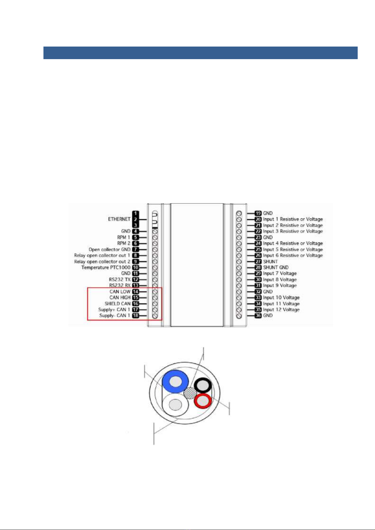
1.2 CAN connection............................................................................................................................. 5
2. MOUNTING THE ALBACOMBI UNIT..................................................................................................... 6
2.1 DIN Rail Mounting ......................................................................................................................... 6
2.2 Connecting to a NMEA 2000 Network .......................................................................................... 6
2.2.1 NMEA 2000 Networks ............................................................................................................ 7
2.2.2 NMEA 2000 Minimum Network Requirements ..................................................................... 7
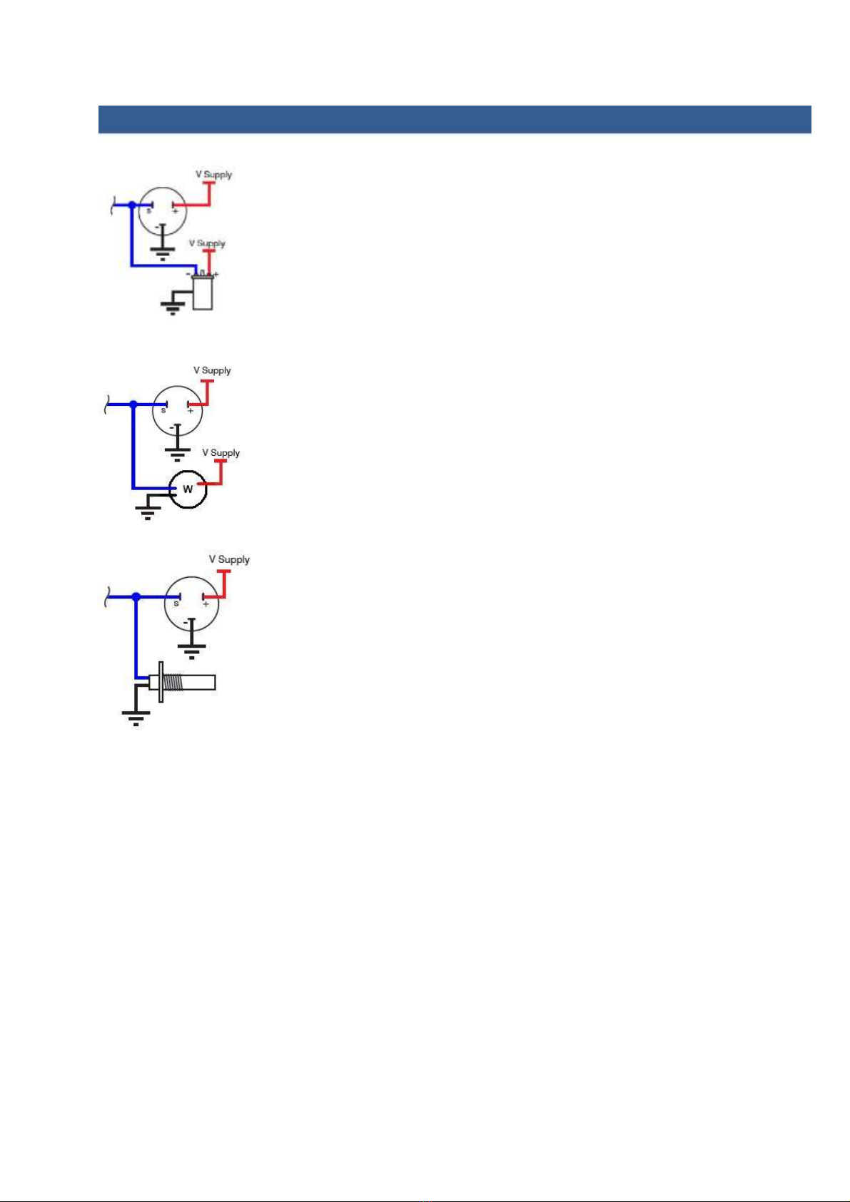
3. TACHO INPUT CONNECTIONS ............................................................................................................. 8
4. CONFIGURING THE ALBACOMBI DEVICE............................................................................................. 9
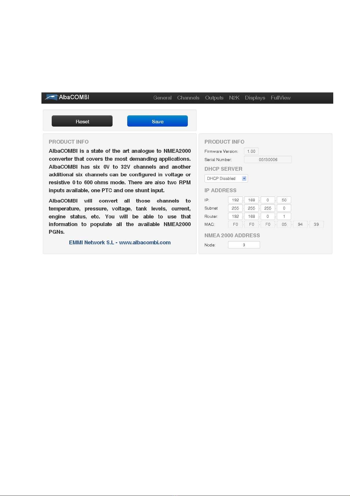
4.1 General Option............................................................................................................................ 10
4.2 Channel Options.......................................................................................................................... 11
4.2.1 RPM Channel........................................................................................................................ 12
4.2.2 PTC1000 Option.................................................................................................................... 14
4.2.3 Volt/Resistive Input.............................................................................................................. 16
4.2.4 Shunt Input........................................................................................................................... 18
4.2.5 Voltage Input........................................................................................................................ 19
4.3 Output Option ............................................................................................................................. 21
4.4 NMEA 2000 Option...................................................................................................................... 22
4.4.1 PGN 127488: Engine Rapid Update...................................................................................... 22
4.4.2 PGN 127489: Engine Parameters Dynamic .......................................................................... 23
4.4.3 PGN 127508: Battery Status................................................................................................. 24
4.4.4 PGN 127505: Fluid Level....................................................................................................... 25
4.4.5 PGN 130312: Temperature .................................................................................................. 26
4.4.6 PGN 130314: Pressure.......................................................................................................... 27
4.7 Displays Option............................................................................................................................ 28
4.8 FULL‐SCREEN OPTION.................................................................................................................. 30
5. SPECIFICATIONS................................................................................................................................. 33

AlbaCombi - Analog to NMEA 2000 Converter page 3/33
Company Information
EMMI NETWORK S.L.
CALLE DELS FURS, 50
46701 GANDiA, VALENCIA SPAIN
www.albacombi.com
No part of this document may be reproduced in any form without the written permission of the copyright owner.
The contents of this document are subject to revision without notice due to continued progress in methodology,
design and manufacturing. EMMI Network SL shall have no liability for any error or damage of any kind resulting
from the use of this document.
The information provided in this document concerning capacity, suitability and performance shall not be
considered commercially binding.
Please note that all capacity figures and dimensioning methods are based on EMMI Network’s SL own models of
how devices behave in a network. The document is intended to be used by professionally trained personnel. It is
strongly recommended to involve EMMI Network SL in discussions covering the contents of this document.
Any feedback that may help EMMI Network SL improve the documentation and information methods is
welcome.
The AlbaCombi has been certified to comply with the European directive for
Electromagnetic Compatibility (EN60945) and is appropriately CE marked. Operation of the
unit should be in conjunction with appropriate CE approved shielded connectors and
cabling used in accordance with the CE directive EN60945. Any EMC related issues should
be reported to Emmi Network S.L. immediately to allow the company to rectify or resolve
EMC related problems in accordance with its obligations under EN60945.
Product Disposal
Please dispose of this product in accordance with the WE EE Directive. The product should be
taken to a registered establishment for the disposal of electronic equipment.

AlbaCombi - Analog to NMEA 2000 Converter page 4/33
PRODUCT OVERVIEW
The new AlbaCombi is a second generation device, built following our successful Alba line of
converters, that translate analogue signals from all over the boat to an NMEA 2000 bus.
The unit has been designed to connect in parallel to an existing gauge, so existing instruments can still be
used.
The AlbaCombi can be used to get engine data, tank levels, alarm status, generic pressure and
temperature indications from any 4‐2 0mA sensor. You get twelve 0V to 32V inputs that can be used
for anything from reading voltages of batteries to interfacing with any analogue gauges. Six channels
can be configured to measure resistance from any industry standard engine sensor. Also there are two
RPM inputs, one PTC temperature input, one shunt and two relay outputs.
All twelve resistance and voltage channels have comprehensive calibration that allow you to create an
8 point calibration table or select a predefined industry standard calibration able for most common
sensors and gauges.
The AlbaCombi has an Ethernet port that will allow web based calibration. Just connect your laptop to
the AlbaCombi via Ethernet and you will get to the calibration and testing page. No calibration tools or
special interfaces are required. This device is future proof and can be upgraded in the field via its
ethernet port. See the configuration instructions to find which senders and PGNs are supported. The
instructions can be found on the website at www.albacombi.com.
1. Select mounting location.
Ensure the AlbaCombi can
be mounted in a suitable
location between the NMEA
2000 bus and the senders
or gauges.
2. Connect the AlbaCombi to
the NMEA 2000 network
3. Connect the Gauge inputs
4. Connect the Power to the
AlbaCombi
5. Configure the AlbaCombi.

AlbaCombi - Analog to NMEA 2000 Converter page 5/33
INSTALLATION
1.1 Selecting a Mounting Location
The following figure shows an example installation. This gives an idea of the connections that need to
be made to install the AlbaCombi. All these connections need to be considered before selecting an
installation location.
Resistive
12Vdc
Mode
RPM
(-)
(+)
1.2 CAN connection

AlbaCombi - Analog to NMEA 2000 Converter page 6/33
2. MOUNTING THE ALBACOMBI UNIT
2.1 DIN Rail Mounting
Requirements:
• A top hat rail, type EN 50 022 or a G section rail, type EN 50 035.
Mounting using a different rail type or an alternative mounting kit may breach the terms and
conditions of the guarantee.
2.2 Connecting to a NMEA 2000 Network
Protective braid
Data:
Blue: NET‐L (CAN‐L)
White: NET‐H (CAN‐H)
Feed:
Red: NET‐S. Positive
Feed +V Black: NET‐C.
Common Feed ‐V
External protective braiding

AlbaCombi - Analog to NMEA 2000 Converter page 7/33
2.2.1 NMEA 2000 Networks
NMEA 2000 devices will only communicate with each other when connected to a powered and
correctly terminated NMEA 2000 network.
All networks need to be powered and terminated correctly to allow data to be transmitted reliably on
the network. T‐Pieces are needed to connect each device to the network. Additional cable lengths can
be used between any of the connectors to extend the length of the network. Ensure the NMEA 2000
rules for cable length are adhered to.
Cable Type
Max Length
Per drop cable
6 m
Sum of all drop cables
72 m
Micro Backbone (terminator to terminator)
100 m
Mini Backbone (terminator to terminator)
200 m
2.2.2 NMEA 2000 Minimum Network Requirements
All NMEA 2000 networks require a 12 V DC supply.
In addition, a correctly functioning network will require the following components :
•1 x Power‐T
•2 x Terminating Resistors
•2 x T‐Pieces (one per connected device)
•1 x NMEA 2000 compatible display
All the required network parts can be supplied by Emmi Network S.L

AlbaCombi - Analog to NMEA 2000 Converter page 8/33
3. TACHO INPUT CONNECTIONS
Ignition Coil
Connect the negative of the ignition coil to the positive RPM input of the
AlbaCombi.
Connect GND to input GND of the AlbaCombi
Alternator
Connect the ‘w’ connection of the alternator to the AlbaCombi RPM
positive input of the AlbaCombi (input (input 5 or 6).
Connect GND input of the alternator to the input 4
Hall Effect and Electronic Pulse Senders
Connect the signal line of the sender to the positive input on the AlbaCombi
Connect GND to GND input of the AlbaCombi

AlbaCombi - Analog to NMEA 2000 Converter page 9/33
4. CONFIGURING THE ALBACOMBI DEVICE
Make all connections. See the pin out of your device:
Configure your AlbaCombi: Connect your laptop to Ethernet port.
Open the browser navigator, preferred Chrome and go to the following address:
http://192.168.0.50/ The first window that you will see is the “Full View” page:
The gauges that you will see are an example

AlbaCombi - Analog to NMEA 2000 Converter page 10/33
4.1 General Option
In this option you can change the Ethernet configuration from the AlbaCombi, enable/disable the DHCP
server and configure the IP address.
The default configuration is DHCP server disabled and IP address 192.168.0.50.
The default NMEA address is 9.
Note that if you connect two or more AlbaCombi, you must change the NMEA address, for example:
you have two AlbaCombi connected on your NMEA network. One will have the NMEA Address 9 and
other will be configured with NMEA Address 10.
If you make any change, press “Save” button and then press “Reset”

AlbaCombi - Analog to NMEA 2000 Converter page 11/33
4.2 Channel Options
In order to configure each connected input, please select the channel, as shown on the following
screen. Once selected please configure it.

AlbaCombi - Analog to NMEA 2000 Converter page 12/33
4.2.1 RPM Channel
You must configure all fields:
•Name: the name of the channel.
•Signal from: In case of RPM signal, the signal is sent by one engine.
•Physic Variable: In case of RPM, the only option is “Rotation Rate”.
•Units: RPM
•Limits high and Low: these limits will be used to set an alarm.
•Filter Level: Please indicate if the level measurement has been made with low, medium or high level.
•Sensor Type: you count with some predefined sensors. You can choose a sensor type and make some
changes.
If you press on “Measure”, the current value of the input will be shown.

AlbaCombi - Analog to NMEA 2000 Converter page 13/33
You can click on RAW and see the current value or you can write the theoretical value of the sensor
output which corresponds to the measurement.
The “Calibrated” button is used to test if your calibration table is correct. Note that you must click on
“Save” before doing the test.
Example: If you have saved the following calibration table:
Measured
RPM
(pulse per cycle)
0
0
600
6000
We assume that the sensor manufacturer indicates these values, therefore 3000 rpm we
should have a measure of 300 pulses per cycle. You can accelerate to see that you have 300
cycles per second (by pressing on Raw until that value appears), then press “Calibrated” and
see the value, if it is about 3000 rpm, the calibration table is correct.
Press “SAVE” when all changes have been made.

AlbaCombi - Analog to NMEA 2000 Converter page 14/33
4.2.2 PTC1000 Option
• Signal from: you can select if the sensor measures the temperature from the engine, battery or it’s
ageneral temperature. It is important to select the correct sensor because otherwise when
configuring the corresponding PGN you won’t have the choice to select this parameter, for
instance, if you choose
Engine, the value will be sent to the NMEA network though the PGN127488 and
PGN127489.
•Physic Variable: In this case, the PTC sensor only works with temperature parameters.
•Units: Select between ºC or K.
•Limits high and low: these limits will be used to set an alarm.
•Filter Level: Please indicate if the level measurement has been made with low, medium or high
level.
•Sensor Type: you have some predefined sensors. You can choose a sensor type and make some
changes on calibration table.
If you press on “Measured” you will see the current value:

AlbaCombi - Analog to NMEA 2000 Converter page 15/33
You can click on RAW and see the current value or you can write the theoretical value of the sensor
output corresponding to the measurement.
The “Calibrated” button is used to test if your calibration table is correct. Note that you must click on
“Save” before make the test.
Example: You has saved the following calibration table:
MEASURED
VALUE
(Ohms)
(Tª) (ºC)
10
15
100
50
180
95
We assume that the sensor manufacturer indicates these values. In this way to 70 ºC we must have a
measure of 140 Ohms. You switch on the engine that you have 140 Ohms (you pressing on Measured
until that value), then press “Calibrated” and see the value, if it is about 70ºC, the calibration table is
correct.
Note that X‐axis values (MEASURE) must increase, from smallest to largest value

AlbaCombi - Analog to NMEA 2000 Converter page 16/33
4.2.3 Volt/Resistive Input
You have six inputs like this. In the Channel screen you will see if the input has been configured on
voltage o resistive mode
•Signal from: You can select the parameter that the input will measure; engine, battery, general
fluid, general temperature, general pressure, switch bank or general fluid.
Signal from
Physic Variable
Engine
Rotation Rate
Pressure
Engine Tilt
Temperature
Voltage
Fluid flow
Battery
Temperature
Voltage
Current
General Fluid
General fluid
General Temperature
General temperature
General Pressure
General Pressure
Switch Bank
Binary
•Limits high and low: these limits will be used to set an alarm.
•Filter Level: please indicate if the level measurement has been made with low, medium or high
level.

AlbaCombi - Analog to NMEA 2000 Converter page 17/33
Sensor Type: You have some predefined sensors. You can choose a sensor type and make some
changes.
•Supply Correction (only on voltage input, not available on resistance mode):
You can activate the supply correction using a voltage input (Correction Channel)

AlbaCombi - Analog to NMEA 2000 Converter page 18/33
4.2.4 Shunt Input
The shunt is a sensor that measures the load or unload current in a battery, and it must have the
right dimensions to stand the maximum current it it supposed to measure.
•Signal from: This parameter can only be obtained from the battery, therefore, will be the only
option in the drop‐down.
•Physic Variable: the only option is current.
•Units: mA or A
•Limits high and low: these limits will be used to set an alarm.
•Filter Level: Indicate if the measures filter has been made with a low, medium or high level.
•Sensor Type: You have some predefined sensors. You can choose a sensor type and make some
changes.
If you press on “Measured” you will see the current value:
You can click on “Measured” and see the current value or you can
write the theoretical value of the sensor output corresponding to the
measurement.
The “Calibrated” button is used to test if your calibration table is
correct. Note that you must click on “Save” before making the test.

AlbaCombi - Analog to NMEA 2000 Converter page 19/33
4.2.5 Voltage Input
•Signal from: You can select the parameter that the input will measure: engine, battery, general
fluid, general temperature, general pressure, switch bank or general fluid.
Signal from
Physic Variable
Engine
Rotation Rate
Pressure
Engine Tilt
Temperature
Voltage
Fluid flow
Battery
Temperature
Voltage
Current
General Fluid
General fluid
General Temperature
General temperature
General Pressure
General Pressure

AlbaCombi - Analog to NMEA 2000 Converter page 20/33
Limits high and low: these limits will be used to set an alarm.
•Filter Level: please indicate if the level measurement has been made with low, medium or high
level.
•Sensor Type: You have some predefined sensors. You can choose a sensor type and make some
changes.
•Supply Correction:
You can activate the supply correction using a voltage input (Correction Channel)
Other manuals for AlbaCombi
1
Table of contents
Other Albatross Media Converter manuals
Popular Media Converter manuals by other brands

Blackmagicdesign
Blackmagicdesign ATEM Camera Converter Installation and operation manual

Data Video
Data Video BAC-03 Quick reference card

Magicfx
Magicfx COMBINER BOX MFX3225 User and installation manual

HIK VISION
HIK VISION DS-6500DI-T user manual

Delta
Delta PMC-05V050W1AA instruction manual

Planet
Planet IGT-805AT user manual

A-Neuvideo
A-Neuvideo ANI-4K-VW instruction manual

TV One
TV One 1T-VS-434 instruction manual

Prism Sound
Prism Sound CALLIA quick start guide

Smart view
Smart view DS-2012F user manual

Clear One
Clear One StreamNet AVoIP VIEW Pro Installation and user manual

Black Box
Black Box LE1502A-R3 Installation and user guide