Albedo AT-2048 Instruction Manual

(C) ALBEDO TELECOM - 2010
Installation and Maintenance of E1 circuits
ALBEDO AT-2048 is a rug-
ged fully featured battery oper-
ated E1/Datacom handheld
tester designed in 2010 provid-
ing easy navigation and high
resolution screen. Low cost, fully
featured, it is a truly perfect field
tool for installation, acceptance
and maintenance of PDH and
Datacom links including bi-di-
rectional (BER) test functions.
A valuable tool that offers
generator, dual analyzer, USB,
Ethernet, and RJ45 interfaces. It
offers Jitter measurements and
pulse mask, therefore it can
monitor slots activity, delay and
frequency measurements fre-
quency measurements over
more than seven hours. Test re-
sults can be saved in a Memory
stick or transferred to a PC.

2
Installation and Maintenance of E1 circuits
1 ANINTRODUCTION TO COMMUNICATIONS SYSTEMS
One of the first communications networks known was built by Mediterranean cul-
tures more than 1,000 years ago and consisted of a series of successive towers with
a distance of about 5 to 12 km between them. A message could be coded and trans-
mitted from the first tower to the second one by using optical signals, and then be
passed on along the line until it reached its final destination.
In this primitive system we can already identify all the elements of a genuine
communications network (see Figure 2):
•Information consists of the messages interchanged between final users. In or-
der to be introduced into the network, information needs to be coded into sig-
nals.
•Signals are a physical magnitude, specific for each transmission medium, that
change with respect to time.
•The transmission medium consists of the links that connect distant nodes.
•Nodes are those network elements that receive the signals and retransmit them
further along until reaching the final users.
Figure 1 ALBEDO AT.2048, E1, Datacom, Jitter, and Wander tester.

E1 testing 3
In other words, in a telecommunications network, user information is distributed as
signals from one point to another through the transmission medium that connects
the nodes in the system.
1.1 Signals and Information
The messages to be transmitted are meaningful for the users and are structured hier-
archically in lexical, syntactic, and semantic layers, in line with the grammar of the
natural language used, whereas signals, by comparison, are only meaningful inside
the telecommunications network. The signals used in telecommunications systems
can be of two types (see Table 1):
1. Analog or continuous: They can take any of an unlimited number of values
within a given range.
2. Digital or discrete: They can only take a limited number of values. In a binary
system, the only valid values are 0 and 1.
Table 1
Combinations of signals and information.
Signal Analog Information Digital Information
Analog Modulation (e.g., AM/FM radio and TV) Digital modulation (e.g., ADSL)
Digital Digitalization (e.g., audio CD, GSM) Coding (e.g., frame relay)
Figure 2 Elements of a telecommunications network.
Source SinkCoder DecoderTransmitter Receiver
line coding
Transmission
medium
line decoding data decodingdata coding
message message
Te r m i na l
Node
Terminal
Node
Network
Nodes
Access Network Access NetworkTransmission Network
Information
Signals
Information
UserUser

ALBEDO AT.2048
4
1.2 Transmission Medium
The transmission medium can be defined as the environment where a signal is
transmitted, be it material (electrical wires, optical fiber, open air, etc.) and nonma-
terial, or vacuum, through which only electromagnetic waves are propagated.
The material transmission medium can be divided into two main groups:
1. A conductive medium, in which the information is transmitted in the form of
electrical impulses. Typical examples of this medium are twisted-pair and
coaxial cables.
2. A dielectric medium, in which the information is transmitted in the form of
radioelectrical or optical signals; for example, the atmosphere and optical fiber.
Transmitted signal
Attenuation
Distortion
Noise
Received signal
Source
Transmitter
Transmission medium
Receiver Sink
distance(d)
PTx
PRx
Figure 3 Effects of attenuation, distortion, and noise on transmission.
Sampling times
Data received
Original data
10 0 0
10 1 0
The propagation of signals over one of these media is what we call transmission.
The success of transmission of information in telecommunications networks de-
pends basically on two factors: the quality of the signal transmitted, and the quality
of the transmission medium used. In addition, there are natural forces that can resist

E1 testing 5
transmission and modify the original characteristics of the signals, which may end
up being degraded by the time they reach their destination.
The most significant impairments are attenuation, noise, and distortion. We
look at these below in respect to a communications channel, which is defined as a
means of unidirectional transmission of signals between two points.
1.2.1 Attenuation
Attenuation weakens the power of the signal proportionally to the transmission me-
dium length. It is expressed in decibels (AdB) through the logarithmic ratio of the
transmitted power (PTx) and received power (PRx), measured at both ends of the
distance (d) being examined (see Figure 3). Transmission media can usually be
characterized by their attenuation per unit of length (AdB / Km):
Example: Thus for a transmission medium with A=0.2 dB/Km, after 15 Km, the at-
tenuation is AdB=3 dB. If the transmitted power is PTx=1W. After 10 Km received
power is PRx= 0.5W, because 10 log (1/PRx) = 3 dB (see Figure 4).
At the far end the received signal must have enough power (PRx) to be interpret-
ed, otherwise amplifiers (also known as repeaters or regenerators in digital transmis-
sion) must be inserted along the transmission medium to improve the power of the
received signal.
10 PTx PRx
⁄()log d AdB Km⁄
⋅=
AdB dA⋅dB Km⁄
=
0.0
0.5
1.0
2.5
3.0
101000 1310 1400 1550
Wavelength (nm)
Attenuation (dBm/Km)
2.5
1.5
Figure 4 Typical attenuation values for single mode optical fiber and coaxial cable.
1
100
Attenuation (dBm/Km)
10
1200 1KHz 100 1MHz 10
Frequency
800
Optical fiber Coaxial cable

ALBEDO AT.2048
6
1.2.2 Distortion
Distortion produces a change in the original shape of the signal at the receiver end.
There are two types: amplitude distortion and delay distortion.
•When the impairments affect the amplitudes of the frequency components of
the signal differently, this is said to produce amplitude distortion (sometimes
called absorption). Amplitude distortion is caused because the transmission
channel is limited to certain frequencies (see Figure 5). To overcome this prob-
lem amplifiers must equalize the signal, separately amplifying each band of
frequencies.1
•When the velocity of propagation of a signal varies with the frequency, there is
said to be delay distortion (sometimes called dispersion). Delay distortion is
particularly disturbing in the digital transmission producing intersymbol inter-
ference (ISI), where a component of the signal of one bit is misplaced in the
time slot reserved for another bit. ISI limits the capacity to extract digital infor-
mation from the received signal.
Harry Nyquist showed that the maximum transmission capacity (C) is limited by
ISI and depends on the channel bandwidth (B) and the number of signal elements
(M) coding the information.
1. Note that attenuation is a specific case of amplitude distortion that equally affects all
frequencies of the signal.
Figure 5 The two basic transmission channels. In the frequency domain the channel transfer
function H(f) determines the attenuation of each frequency and consequently the
amplitude distortion.
f
f
fof2
f1
Bandwidth Bandwidth
H(f)
H(f)
Lowpass Bandpass
Cbps 2Blog2M=

E1 testing 7
Example: For a modem using 16 signal elements and a channel bandwidth (B) of
4,000 hertz (Hz), the maximum data transfer rate (C) is 32,000 bits per second
(bit/s).
1.2.3 Noise
Noise refers to any undesired and spurious signal that is added to an information
signal. It is usually divided into five categories:
1. Thermal noise: This is caused by the agitation of electrons in any conductor in
a temperature different than absolute zero. The noise (N) is independent of the
frequency and proportional to the bandwidth (B) and the temperature (T) in
degrees Kelvin:
NkTB⋅⋅=
(k is the Boltzmann’s constant in joules/kelvin, k = 1.3803 x 10⁻²³)
2. Intermodulation noise: This is caused when two or more signals of frequencies
f1and f2, transmitted in the same medium, produce a spurious signal at fre-
quencies that are a linear combination of the previous ones.
3. Atmospheric noise: This is caused by the static discharge of clouds, or ionized
gas from the sun, or high frequency signals radiated by the stars.
4. Impulse noise: Of short duration but high amplitude, these energy bursts are
caused by sources such as electrical machinery, a drop in voltage, atmospheric
interference, and so on. These do not tend to be a problem for analog signals,
but are a prime cause of errors in digital transmission.
5. Crosstalk: Whenever a current flows through a conductor a magnetic field is
set up around it that can induct a current into a second conductor collocated in
a short distance.
Noise is always present in transmission channels, even when no signal is being
transmitted. A key parameter at the receiver end to distinguish between information
and spurious power is the signal-to-noise ratio (S/N):
Claude Shannon proved that the signal-to-noise ratio (S/N) determines the the-
oretical maximum transmission capacity (C) in bits per second of channel with a lim-
ited bandwidth (B):
SN⁄()
dB 10 PowerSignal PowerNoise
⁄()log=
Cbps Blog21SN⁄+()=

ALBEDO AT.2048
8
Example: A typical value of S/N for a voice grade line is 30 dB (equivalent to a
power ratio of 1,000:1). Thus for a bandwidth of 3,100 Hz the maximum data trans-
fer rate (C) should be 30,894 bit/s.
If we pay attention only to the Nyquist formula (see Section 1.2.2) we could in-
accurately conclude that for a given bandwidth (B) the data rate can be increased
endlessly, by increasing the number of signal elements. However in reality, the sig-
nal-to-noise ratio sets up the theoretical limit of the channel capacity.
The Shannon theorem makes no statement as to how the channel capacity is
achieved. In fact, channels only approach this limit. The task of providing high chan-
nel efficiency is the goal of coding techniques.
1.2.4 The transmission channel
A digital channel is a communication subsystem with capacity to send and receive
information between two points: a source and a sink. Related concepts are:
•Bandwidth, expressed in hertz (Hz). This is the difference between the highest
and the lowest frequency that can be transmitted across a line or a network.
•Data rate, expressed in bits per second (bit/s). This is a measure of the speed
with which information is transferred. It depends on the bandwidth, transmis-
sion medium impairments, and the technological capacity to efficiently use the
available bandwidth.
•Performance, expressed in bit error rate (BER). This is the probability of a sin-
gle bit being corrupted in a defined interval. Performance is on indication of
the quality of the channel.
Channel capacity is the data rate that can be transmitted over a communication path
under specific conditions.When two channels define a two-way communication, it
is more usual to talk about a circuit.
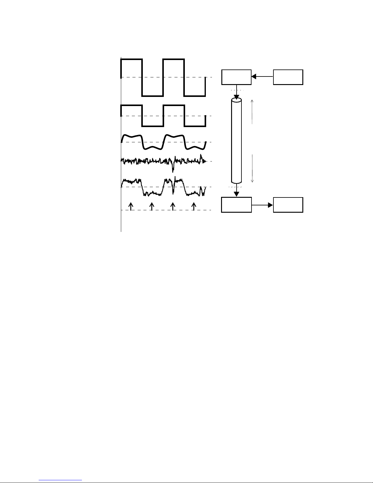
1.3 Channel Coding
Channel coding is the process that transforms binary data bits into signal elements
that can cross the transmission medium. In the simplest case, in a metallic wire a bi-
nary 0 is represented by a lower voltage, and a binary 1 by a higher voltage. How-
ever, before selecting a coding scheme it is necessary to identify some of the
strengths and weaknesses of line codes:
•High-frequency components are not desirable because they require more chan-
nel bandwidth, suffer more attenuation, and generate crosstalk in electrical
links.

E1 testing 9
•Direct current (dc) components should be avoided because they require physi-
cal coupling of transmission elements. Since the earth/ground potential usually
varies between remote communication ends, dc provokes unwanted earth-re-
turn loops.
•The use of alternating current (ac) signals permits a desirable physical isola-
tion using condensers and transformers.
•Timing control permits the receiver to correctly identify each bit in the trans-
mitted message. In synchronous transmission, the timing is referenced to the
transmitter clock, which can be sent as a separate clock signal, or embedded
into the line code. If the second option is used, then the receiver can extract its
clock from the incoming data stream thereby avoiding the installation of an ad-
ditional line.
In order to meet these requirements, line coding is needed before the signal is trans-
mitted, along with the corresponding decoding process at the receiving end. There
are a number of different line codes that apply to digital transmission, the most
widely used ones are alternate mark inversion (AMI), high-density bipolar three ze-
ros (HDB3), and coded mark inverted (CMI).
1.3.1 Non-return to zero
Non-return to zero (NRZ) is a simple method consisting of assigning the bit “1”
to the positive value of the signal amplitude (voltage), and the bit “0” to the nega-
tive value (see Figure 6). There are two serious disadvantages to this:
1. No timing information is included in the signal, which means that synchronism
can easily be lost if, for instance, a long sequence of zeros is being received.
2. The spectrum of the signal includes a dc component.
1.3.2 Alternate mark inversion
Alternate mark inversion (AMI) is a transmission code, also known as pseudo-
ternary, in which a “0” bit is transmitted as a null voltage and the “1” bits are repre-
sented alternately as positive and negative voltage. The digital signal coded in AMI
is characterized as follows (see Figure 6):
•The dc component of its spectrum is null.
•It does not solve the problem of loss of synchronization with long sequences of
zeros.

Figure 6 Line encoding technologies. AMI and HDB3 are usual in electrical signals, while
CMI is often used in optical signals.
0
B8ZS
HDB3
CMI
0
+V
-V
0
+V
-V
0
+V
-V
0
+V
-V
0 0 0 V
B 0 0 V
B 0 0 V
Bipolar
Eight-Zero
Suppression
High
Density
Bipolar
Three
Zeros
Coded
Mark
Inverted
B: balancing
V: violation
NRZ 0
+V
-V
Non-
Return to
Zero
AMI
Alternate
Mark
Inversion
- 0 0 0 V + 0
010001 11000 00 00010
V -
ALBEDO AT.2048
10
1.3.3 Bit eight-zero suppression
Bit eight-zero suppression (B8ZS) is a line code in which bipolar violations are de-
liberately inserted if the user data contains a string of eight or more consecutive ze-
ros. The objective is to ensure a sufficient number of transitions to maintain the
synchronization when the user data stream contains a large number of consecutive
zeros (see Figure 1.5 and Figure 1.6).
The coding has the following characteristics:
•The timing information is preserved by embedding it in the line signal, even
when long sequences of zeros are transmitted, which allows the clock to be re-
covered properly on reception
•The dc component of a signal that is coded in B8Z3 is null.
1.3.4 High-density bipolar three zeroes
High-density bipolar three zeroes (HDB3) is similar to B8ZS, but limits the maxi-
mum number of transmitted consecutive zeros to three (see Figure 6). The basic
idea consists of replacing a series of four bits that are equal to “0” with a code word

E1 testing 11
“000V” or “B00V,” where “V” is a pulse that violates the AMI law of alternate po-
larity, and B it is for balancing the polarity.
•“B00V” is used when, until the previous pulse, the coded signal presents a dc
component that is not null (the number of positive pulses is not compensated
by the number of negative pulses).
•“000V” is used under the same conditions as above, when, until the previous
pulse, the dc component is null (see Figure 7).
•The pulse “B” (for balancing), which respects the AMI alternation rule and has
positive or negative polarity, ensuring that two consecutive “V” pulses will
have different polarity.
1.3.5 Coded mark inverted
The coded mark inverted (CMI) code, also based on AMI, is used instead of HDB3
at high transmission rates, because of the greater simplicity of CMI coding and de-
coding circuits compared to the HDB3 for these rates. In this case, a “1” is transmit-
ted according to the AMI rule of alternate polarity, with a negative level of voltage
during the first half of the period of the pulse, and a positive level in the second
half. The CMI code has the following characteristics (see Figure 6):
•The spectrum of a CMI signal cancels out the components at very low frequen-
cies.
•It allows for the clock to be recovered properly, like the HDB3 code.
•The bandwidth is greater than that of the spectrum of the same signal coded in
AMI.
1.4 Multiplexing and Multiple Access
Multiplexing is defined as the process by which several signals from different chan-
nels share a channel with greater capacity (see Figure 8). Basically, a number of
Figure 7 B8ZS and HDB3 coding. Bipolar violations are: V+ a positive level and V-negative.
+
–
Last pulse
polarity
B8ZS Number of ones
B-00V-
+
–
Last ‘1’
polarity
HDB3
000V-B+00V+
000V+
Odd Even
Substitution
000V
+
–0V
-
+
000V
-
+0V
+
–

ALBEDO AT.2048
12
channels share a common transmission medium with the aim of reducing costs and
complexity in the network. When the sharing is carried out with respect to a remote
resource, such as a satellite, this is referred to as multiple access rather than multi-
plexing.
Some of the most common multiplexing technologies are:
1. Frequency division multiplexing/frequency division multiple access (FDM/
FDMA): Assigns a portion of the total bandwidth to each of the channels.
2. Time-division multiplexing/time division multiple access (TDM/TDMA):
Assigns all the transport capacity sequentially to each of the channels.
3. Code-division multiplexing access (CDMA): In certain circumstances, it is
possible to transmit multiple signals in the same frequency, with the receiver
being responsible for separating them. This technique has been used for years
in military technology, and is based on artificially increasing the bandwidth of
the signal according to a predefined pattern.
4. Polarization division multiple access (PDMA): Given that polarization can be
maintained, the polarization direction can be used as a multiple access tech-
nique, although when there are many obstacles, noise can make it unsuitable,
DTE-A
B1
DTE-B
B2
DTE-n
Bn
.
.
.
Figure 8 Multiplexing consolidates lower capacity channels into a higher capacity channel.
Frequency division multiplexing access (FMDA) is used by radio, TV, and global
system mobile (GSM). Time division multiplexing access (TDMA) is used by the
integrated services digital network (ISDN), frame relay (FRL), and GSM. Code
division multiplexing access (CDMA) is used by the third generation networks
(3G) of mobiles.
A
A
B
C
D
E
F
BCDEFAB
TDMAFDMA
time
001011101110111001
110100010110111001
code bit
CDMA
frequency
DTE-A B1
DTE-B B2
DTE-n
Bn
.
.
.Transmission media
ΣBi
n
m
n
m
Multiplexer Demultiplexer
Multiplexing
Bi= bandwidth
.
.
.
.
.
.
Multiplexing technologies
pattern
data
signal
01

E1 testing 13
which is why it is not generally used in indoor installations. Outside, however,
it is widely exploited to increase transmission rates in installations that use
microwaves.
5. Space division multiple access (SDMA): With directional antennas, the same
frequency can be reused, provided the antennas are correctly adjusted. There is
a great deal of interference, but this system lets frequencies obtain a high
degree of reusability.
2 PULSE CODE MODULATION
The pulse code modulation (PCM) technology (see Figure 9) was patented and de-
veloped in France in 1938, but could not be used because suitable technology was
not available until World War II. This came about with the arrival of digital sys-
tems in the 1960s, when improving the performance of communications networks
became a real possibility. However, this technology was not completely adopted
until the mid-1970s, due to the large amount of analog systems already in place and
the high cost of digital systems, as semiconductors were very expensive. PCM’s
initial goal was that of converting an analog voice telephone channel into a digital
one based on the sampling theorem (see Figure 10):
Figure 9 Pulse code modulation (PCM) was the technology selected to digitalize the voice in
telephone networks. Other pulse techniques are pulse amplitude modulation
(PAM), pulse duration modulation (PDM), and pulse position modulation (PPM).
PAM
3
7
3
-3
-1to
PDM
131 54
t
tot
PPM
tot
tot
PCM
131 54
0 110 0 1 0 0 11 011 00
Amplitude
Sampling
tot
7
3
-1
-3
V
Pulse modulation techniques

ALBEDO AT.2048
14
The sampling theorem states that for digitalization without information loss, the
sampling frequency (fs)should be at least twice the maximum frequency component
(fmax)of the analog information:
The frequency 2·fmax is called the Nyquist sampling rate. The sampling theorem
is considered to have been articulated by Nyquist in 1928, and mathematically prov-
en by Shannon in 1949. Some books use the term Nyquist sampling theorem, and
others use Shannon sampling theorem. They are in fact the same theorem.
PCM involves three phases: sampling, encoding, and quantization:
1. In sampling, values are taken from the analog signal every 1/fsseconds (the
sampling period).
2. Quantization assigns these samples a value by approximation, and in accor-
dance with a quantization curve (i.e., A-law of ITU-T 2).
3. Encoding provides the binary value of each quantified sample.
2. This is a International Telecommunication Union (ITU-T) ratified audio encoding and
compression technique (Rec. G.711). Among other implementations, A-law was orig-
inally intended as a phone-communications standard.
fs2f⋅max
>
Figure 10 The three steps of digitalization of a signal: sampling of the signal, quantization of
the amplitude, and binary encoding.
Amplitude (volts)
0
Sampling time
T
n
Sampling
2T
Code Amplitude
1
Quantization
1
2
3
5
6
4
Analog Signal
000
001
011
101
111
010
100
110
Coding
t
t
t
1 111111 1 1100 000 000000
01
2
3
3T 4T 5T
V
T2T t
3T 4T 5T

E1 testing 15
A telephone channel admits frequencies of between 300 Hz and 3,400 Hz. Because
margins must be established in the channel, the bandwidth is set at 4 kHz. Then the
sampling frequency must be ; equivalent to a sample
period of .
In order to codify 256 levels, 8 bits are needed, where the PCM bit rate (v) is:
This bit rate is the subprimary level of transmission networks.
3 PDH AND T-CARRIER
At the beginning of the 1960s, the proliferation of analog telephone lines, based on
copper wires, together with the lack of space for new installations, led the transmis-
sion experts to look at the real application of PCM digitalization techniques and
TDM multiplexing. The first digital communications system was set up by Bell
Labs in 1962, and consisted of 24 digital channels running at what is known as T1.
fs2 4 000,8 000,=Hz⋅≥
T 1 8 000,125μs=⁄=
v 8 000,samples s⁄8bits sample⁄
×64Kbps==
139264 kbit/s
34368 kbit/s
8448 kbit/s
97728 kbit/s
6312 kbit/s
Figure 11 The PDH and T-carrier hierarchies, starting at the common 64-kbit/s channel and
the multiplexing levels. Most of the narrowband networks are built on these stan-
dards: POTS, FRL, GSM, ISDN, ATM (asynchronous transfer mode), and leased
lines to transmit voice, data, and video.
139264 kbit/s
x4
34368 kbit/s
x4
8448 kbit/s
x4
2048 kbit/s
64 kbit/s
1544 kbit/s
x2
44736 kbit/s 32064 kbit/s
97728 kbit/s
x3
x30 x24
x3
x7 x5
x3
4th Level
3rd Level
2nd Level
PDH T-carrier
Japan
Single Channel
1st Level
E4
E3
E2
E1 T1 J1
T2 J2
J3
J4
T3
6312 kbit/s
U.S. and Canada
3152 kbit/s
x2
T1c J1c
worldwide
PDH

ALBEDO AT.2048
16
3.1 Basic Rates: T1 and E1
In 1965, a standard appeared in the U.S. that permitted the TDM multiplexing of 24
digital telephone channels of 64 kbit/s into a 1.544-Mbit/s signal with a format
called T1 (see Figure 11). For the T1 signal, a synchronization bit is added to the
24 TDM time slots, in such a way that the aggregate transmission rate is:
125 μs is the sampling period
Europe developed its own TDM multiplexing scheme a little later (1968), al-
though it had a different capacity: 32 digital channels of 64 kbit/s (see Figure 11).
The resulting signal was transmitted at 2.048 Mbit/s, and its format was called E1
which was standardized by the ITU-T and adopted worldwide except in the U.S.,
Canada, and Japan. For an E1 signal, the aggregate transmission rate can be obtained
from the following equation:
4 THE E1 FRAME
The E1 frame defines a cyclical set of 32 time slots of 8 bits. The time slot 0 is de-
voted to transmission management and time slot 16 for signaling; the rest were as-
signed originally for voice/data transport (see Figure 12).
The main characteristics of the 2-Mbit/s frame are described in the following.
4.1 Frame Alignment
In an E1 channel, communication consists of sending consecutive frames from the
transmitter to the receiver. The receiver must receive an indication showing when
the first interval of each frame begins, so that, since it knows to which channel the
information in each time slot corresponds, it can demultiplex correctly. This way,
the bytes received in each slot are assigned to the correct channel. A synchroniza-
tion process is then established, and it is known as frame alignment.
4.2 Frame Alignment Signal
In order to implement the frame alignment system so that the receiver of the frame
can tell where it begins, there is what is called a frame alignment signal (FAS) (see
Figure 13). In the 2Mbit/s frames, the FAS is a combination of seven fixed bits
(“0011011”) transmitted in the first time slot in the frame (time slot zero or TS0).
For the alignment mechanism to be maintained, the FAS does not need to be trans-
24channels 8bit channel⁄1bit
+×()125μs⁄1,544Mbps=
32channels 8bit channel⁄
×()125μs⁄2,048Mbps=

E1 testing 17
mitted in every frame. Instead, this signal can be sent in alternate frames (in the
first, in the third, in the fifth, and so on). In this case, TS0 is used as the synchroni-
zation slot. The TS0 of the rest of the frames is therefore available for other func-
tions, such as the transmission of the alarms.
4.3 Multiframe CRC-4
In the TS0 of frames with FAS, the first bit is dedicated to carrying the cyclic re-
dundancy checksum (CRC). It tells us whether there are one or more bit errors in a
specific group of data received in the previous block of eight frames known as sub-
multiframe (see Figure 14).
0 1C10 1 0 1 1 0 00 0 S A S S
A S0 1 S S S S c1 d1a1 b1 a16 b16 c16 d16
c2 d2a2 b2 a17 b17 c17 d170 1C20 1 0 1 1
A S0 1 S S S S c3 d3a3 b3 a18 b18 c18 d18
c4 d4a4 b4 a19 b19 c19 d190 1C30 1 0 1 1
Frame 0
1
2
3
4
A S0 1 S S S S c5 d5a5 b5 a20 b20 c20 d20
c6 d6a6 b6 a21 b21 c21 d210 1C40 1 0 1 1
A S0 1 S S S S c7 d7a7 b7 a22 b22 c22 d22
5
6
7
A S0 1 S S S S c9 d9a9 b9 a24 b24 c24 d24
c10 d10a10 b10 a25 b25 c25 d250 1C20 1 0 1 1
A S0 1 S S S S c11 d11a11 b11 a26 b26 c26 d26
c12 d12a12 b12 a27 b27 c27 d270 1C30 1 0 1 1
9
10
11
12
A SE 1 S S S S c13 d13a13 b13 a28 b28 c28 d28
c14 d14a14 b14 a29 b29 c29 d290 1C40 1 0 1 1
A SE 1 S S S S c15 d15a15 b15 a30 b30 c30 d30
13
14
15
c8 d8a8 b8 a23 b23 c23 d230 1C10 1 0 1 1
8
Time Slot 0 1 15 Time Slot 16. . . 17 31. . .
125 μs
Submultiframe I
Submultiframe II
2ms
Channel 1 15 16 30. . .
. . .
Remote Alarm Indicator
Channel CAS Bits
Alignment Bits
CRC-4 Bits
CRC-4 Error Signaling Bits
C1
A
S
E
a17 b17 c17 d17
C2C3C4
Spare Bits
1 0
...
Channel Bytes
Figure 12 The E1 frame is the first hierarchy level, and all the channels are fully synchronous.
0 1C10 1 0 1 1 0 00 0 S A S S
A S0 1 S S S S c 1 d1a1 b1 a16 b16 c16 d16
c2 d2a2 b2 a17 b17 c17 d170 1C20 1 0 1 1
A S0 1 S S S S c 3 d3a3 b3 a18 b18 c18 d18
c4 d4a4 b4 a19 b19 c19 d190 1C30 1 0 1 1
0
1
2
3
4
A S0 1 S S S S c 5 d5a5 b5 a20 b20 c20 d20
c6 d6a6 b6 a21 b21 c21 d210 1C40 1 0 1 1
A S0 1 S S S S c 7 d7a7 b7 a22 b22 c22 d22
5
6
7
A S0 1 S S S S c 9 d9a9 b9 a24 b24 c24 d24
c10 d10a10 b10 a25 b25 c25 d250 1C20 1 0 1 1
A S0 1 S S S S db b d
9
10
11
c8 d8a8 b8 a23 b23 c23 d230 1C10 1 0 1 1
8
Time Slot 0 1 15 Time Slot 16. . . 17 31. . .
125 μs
Submultiframe I
Sub-multiframe II
c6 d6a6 b6 a21 b21 c21 d21C4
A S0 S S S S c 7 d7a7 b7 a22 b22 c22 d22
6
7
A S0 S S S S c 9 d9a9 b9 a24 b24 c24 d24
c10 d10a10 b10 a25 b25 c25 d25C2
A S0 S S S S db b d
9
10
11
c8 d8a8 b8 a23 b23 c23 d23C1
8
Submultiframe II
011011
011011
011011
1
1
1
0
0
0
FAS
NFAS
011011
011011
1
1
0
0
011011
011011
011011
1
0
0
0
Figure 13 The E1 multiframe uses the FAS code only transmitted in even frames. The NFAS
frames are the odd ones, using a bit equal to “1” to avoid coincidences.

ALBEDO AT.2048
18
4.3.1 The CRC-4 procedure
The aim of this system is to avoid loss of synchronization due to the coincidental
appearance of the sequence “0011011” in a time slot other than the TS0 of a frame
with FAS. To implement the CRC code in the transmission of 2-Mbit/s frames, a
CRC-4 multiframe is built, made up of 16 frames. These are then grouped in two
blocks of eight frames called submultiframes, over which a CRC checksum or word
of four bits (CRC-4) is put in the positions Ci(bits #1, frames with FAS) of the next
submultiframe.
At the receiving end, the CRC of each submultiframe is calculated locally and
compared to the CRC value received in the next submultiframe. If these do not co-
incide, one or more bit errors is determined to have been found in the block, and an
alarm is sent back to the transmitter, indicating that the block received at the far end
contains errors (see Table 2).
4.3.2 CRC-4 multiframe alignment
The receiving end has to know which is the first bit of the CRC-4 word (C1). For
this reason, a CRC-4 multiframe alignment word is needed. Obviously, the receiver
has to be told where the multiframe begins (synchronization).
The CRC-4 multiframe alignment word is the set combination “001011,” which
is introduced in the first bits of the frames that do not contain the FAS signal.
Figure 14 The CRC-4 provides error monitoring by means of four Ci bits that correspond to
the previous submultiframe. If the receiver detects errors, it sets the E-bit to indi-
cate the error. The “001011”sequence is used to synchronize the submultiframe.
010 1011
A S1 S S S S
010 1011
A S1 S S S S
0 101011
1
3
A S1 S S S S
0 101011
A S1 S S S S
5
7
A S1 S S S S
0 101 0 1 1
A S1 S S S S
0 10 1 0 1 1
9
11
A S1 S S S S
0 10 1 0 1 1
A S1 S S S S
13
15
0 101 0 1 1
8
0
0
0
0
0
0
E
E
C1
0C1
2
4
6
10
C2
C3
C4
C2
14 C4
12 C3
Submultiframe I
Submultiframe II
0 10 1 0 1 1
A S1 S S S S
0 10 1 0 1 1
A S1 S S S S
0 10 1 0 1 1
0
A S1 S S S S
0 10 1 0 1 1
A S1 S S S S
A S1 S S S S
0 10 1 0 1 1
A S1 S S S S
0 10 1 0 1 1
10
12
A S1 S S S S
0 10 1 0 1 1
A S1 S S S S
14
0 10 1 0 1 1
C1
C2
C3
2
4
C4
6
C2
C3
C4
C1
8
0
1
11
13
15
0
3
1
0
5
7
1
1
9
E
E
Submultiframe I
Submultiframe II

E1 testing 19
4.3.3 Advantages of the CRC-4 method
The CRC-4 method is mainly used to protect the communication against a wrong
frame alignment word, and also to provide a certain degree of monitoring of the bit
error rate (BER), when this has low values (around 10-6). This method is not suit-
able for cases in which the BER is around 10-3 (where each block contains at least
one errored bit).
Another advantage in using the CRC is that all the bits transmitted are checked,
unlike those systems that only check seven bits (those of the FAS, which are the only
ones known in advance) out of every 512 bits (those between one FAS and the next).
However, the CRC-4 code is not completely infallible, since there is a probability of
around 1/16 that an error may occur and not be detected; that is, that 6.25% of the
blocks may contain errors that are not detected by the code.
4.3.4 Monitoring errors
The aim of monitoring errors is to continuously check transmission quality without
disturbing the information traffic and, when this quality is not of the required stan-
dard, taking the necessary steps to improve it. Telephone traffic is two way, which
means that information is transmitted in both directions between the ends of the
communication. This in its turn means that two 2-Mbit/s channels and two direc-
tions for transmission must be considered.
The CRC-4 multiframe alignment word only takes up six of the first eight bits
of the TS0 without FAS. There are two bits in every second block or submultiframe,
whose task is to indicate block errors in the far end of the communication. The mech-
anism is as follows: Both bits (called E-bits) have “1” as their default value. When
Figure 15 The A multiplexer calculates and writes the CRC code, and the multiplexer B reads
and checks the code. When errors affect the 2-Mbit/s frame, the multiplexer B indi-
cates the problem by means of the E-bit of the frame which travels toward the mul-
tiplexer B.
REBE (bit E=1)
CRC-4 Writer CRC-4 Reader
2
2
Errors
Multiplexer A Multiplexer B
Error Indication Reader Error Indication Writer
.
.
.
.
.
.
64
64
2Mbit/s
64 kbit/s 64 kbit/s

ALBEDO AT.2048
20
the far end of the communication receives a 2Mbit/s frame and detects an erroneous
block, it puts a “0” in the E-bit that corresponds to the block in the frame being sent
along the return path to the transmitter (see Figure 15). This way, the near end of the
communication is informed that an erroneous block has been detected, and both ends
have the same information: one from the CRC-4 procedure and the other from the
E bits. If we number the frames in the multiframe from 0 to 15, the E-bit of frame 13
refers to the submultiframe I (block I) received at the far end, and the E-bit of
frame 15 refers to the submultiframe II (block II).
4.4 Supervision Bits
The bits that are in position 2 of the TS0 in the frame that does not contain the FAS
are called supervision bits and are set to “1,” to avoid simulations of the FAS sig-
nal.
4.5 NFASs - Spare Bits
The bits of the TS0 that do not contain the FAS in positions 3 to 8 make up what is
known as the non-frame alignment signal or NFAS. This signal is sent in alternate
frames (frame 1, frame 3, frame 5, etc.). The first bit of the NFAS (bit 3 of the TS0)
is used to indicate that an alarm has occurred at the far end of the communication.
When operating normally, it is set to “0,” while a value of “1” indicates an alarm.
The bits in positions 4 to 8 are spare bits (see Figure 16), and they do not have
one single application, but can be used in a number of ways, as decided by the tele-
communications carrier. In accordance with the ITU-T Rec. G.704, these bits can be
used in specific point-to-point applications, or to establish a data link based on mes-
sages for operations management, maintenance or monitoring of the transmission
quality, and so on. If these spare bits in the NFAS are not used, they must be set to
“1” in international links.
4.6 NFAS - Alarm Bit
The method used to transmit the alarm makes use of the fact that in telephone sys-
tems, transmission is always two way (see Figure 17). Multiplexing/demultiplexing
devices (known generically as multiplex devices) are installed at both ends of the
0C30
411011
0C20
211011
0C10 0 00 0
0 1 c1 d1a1 b1 a16 b16 c16 d16
c2 d2a2 b2 a17 b17 c17 d17
0 1 c3 d3a3 b3 a18 b18 c18 d18
c4 d4a4 b4 a19 b19 c19 d19
Frame 0
1
3
0 1 c5 d5a5 b5 a20 b20 c20 d20
c6 d6a6 b6 a21 b21 c21 d210 1C40 1 0 1 1
5
6
A
A
A
AS S S11011
SSSSS
SSSSS
SSSSS
Figure 16 Spare bits in the E1 frame.
This manual suits for next models
1
Table of contents
Popular Test Equipment manuals by other brands

WIKA
WIKA CPB 5000 DP operating instructions

Keysight Technologies
Keysight Technologies E7515A Getting started guide

Würth
Würth Elmo Multi-Tester LED operating instructions

Sharps Comliance
Sharps Comliance 15001 Instructions for use

Canon
Canon imageFORMULA ScanFront 400 Service guide

XS Instruments
XS Instruments 1-5 Series instruction manual