3 Brief Survey
3.1 General Information
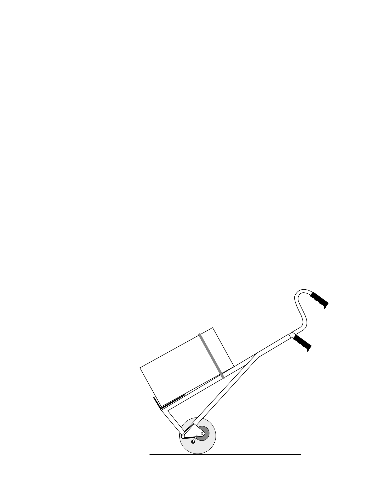
Everybody who sees the CargoMaster in action for the first
time is fascinated by its climbing mechanism.
Precisely those people who are technically inclined end up
shaking their heads as they try to understand how it works.
If one did not see the CargoMaster actually climb up- and
downstairs, one would reach the conclusion that this
couldn’t possibly work, and yet it does.
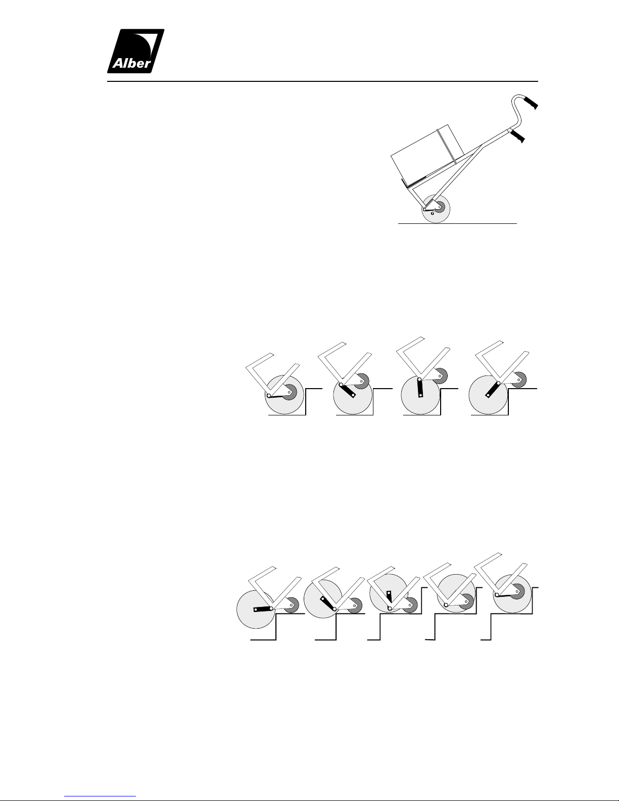
3.2 The Functional Principle
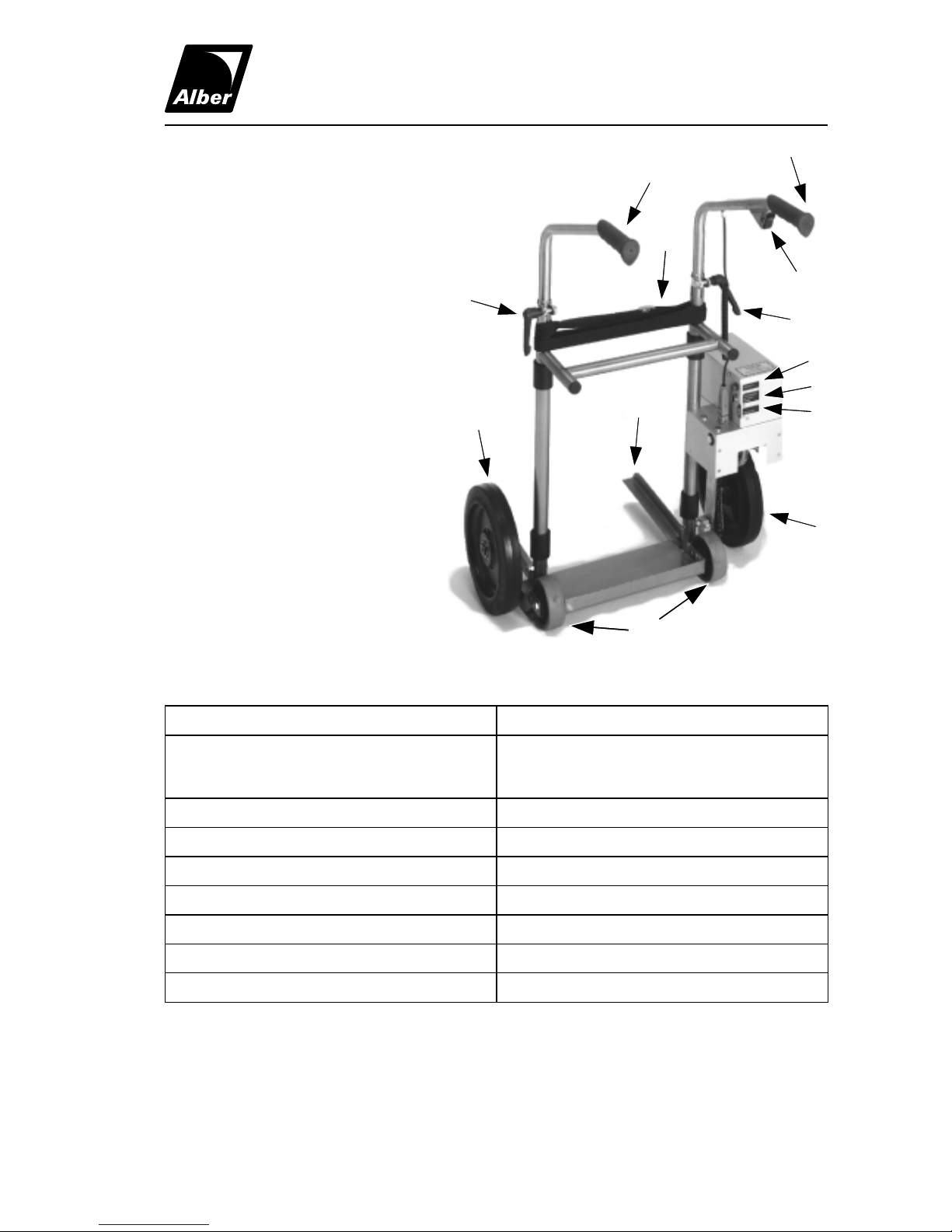
The major focus lies at the axle (F) at the frame (A) of the
CargoMaster around which the lifting levers (E) together with
the big wheels (C) rotate (see 3.3 “Functional Sequence”).
The big wheels are not powered; instead they rotate freely
on the motor shaft. The small supporting wheels (B) are also
not powered but rotate freely.
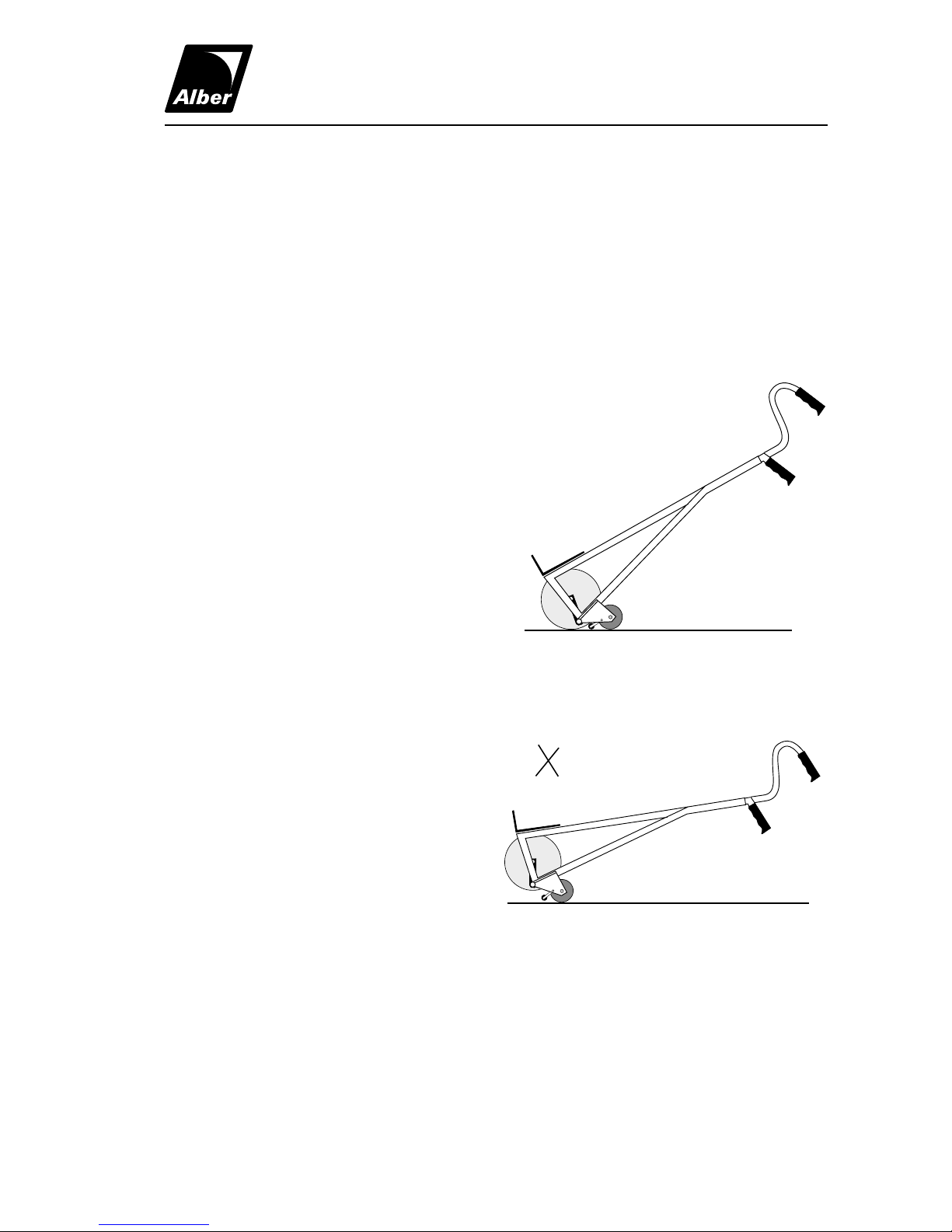
The lifting levers are fixed to the motor shaft by means of
teeth. If the motor rotates, then the lifting levers inevitably
also rotate around the axis (D), which is both the axis of the
motor shaft as well as of the not powered big wheels. The
other ends of the lifting levers, as described previously, ro-
tate freely around the axis (F) attached to the frame of the
CargoMaster. This free rotation inevitably results in the clim-
bing process’ intended up or down movement of either the
big wheels or the frame of the CargoMaster on the stairs.
Depending on the constellation of the frame, lifting levers,
and big wheels to each other certain positions follow in
which one can either drive or park the CargoMaster.
How one can use the up and down movement of the big
wheels and the frame of the CargoMaster to climb stairs is
shown and described in detail as follows.
CargoMaster
A130 GB 7/98
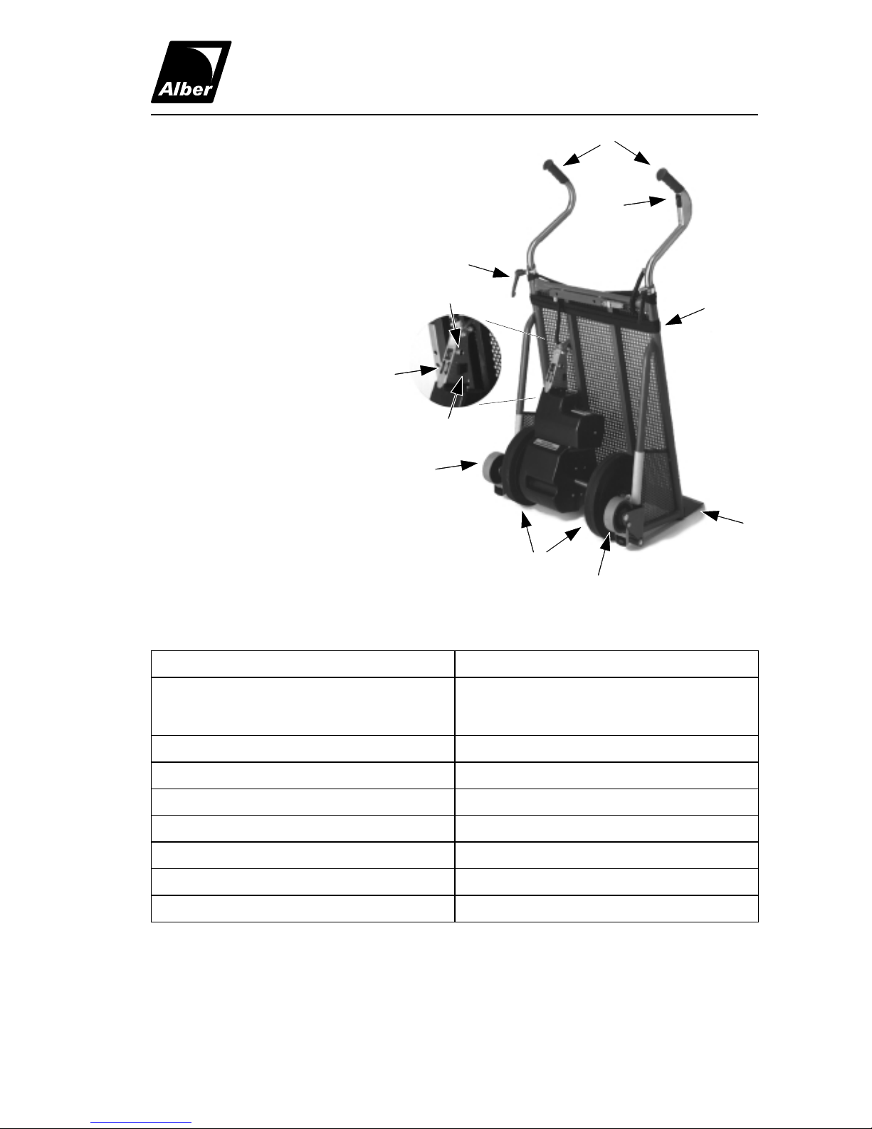
A
B
C
D
E
F
FIGURE 1
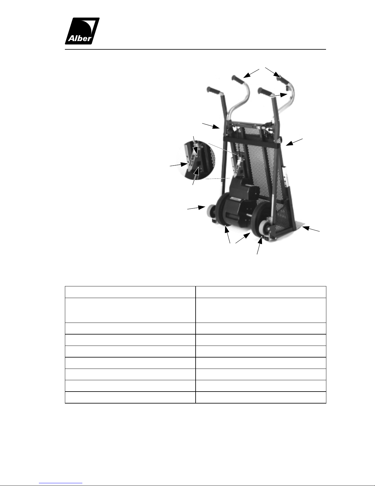
D
F
FIGURE 2