ALBIN PUMP AD15 User manual

since 1928
ALBIN PUMP AD
AIR OPERATED FLOATING DIAPHRAGM PUMPS
INSTRUCTION MANUAL
AD Instruction Manual-2011EE-GB.indd 1 25/07/11 09:45

2
AD
since 1928
AD
since 1928
DECLARATION OF CONFORMITY
(Directive 98/37/EG, Annex IIA)
Manufacturer
ALBIN PUMP AB
Ålegårdsgatan 1
SE-431 50 Mölndal
Sweden
We declare under our sole responsibility that the product :
ALBIN AD
Air Operated Diaphragm Pumps
Type: AD15, AD30, AD60, AD120
are in conformity with COUNCIL DIRECTIVE on the approximation of the laws of the
Member States relating to Machinery 98/37/EG.
Declaration of incorporation
(Directive 98/37/EG, Annex IIB)
AD, Air Operated Diaphragm Pumps, must not be put into service until the machinery
into which it is to be incorporated has been declared in conformity with the provisions
of the Directive.
Mölndal, Sweden, 02.05.2006
Christian Söderholm
Managing director
AD Instruction Manual-2011EE-GB.indd 2 25/07/11 09:45

3
AD
since 1928
AD since 1928
INDEX
1 / INTRODUCTION
1.1 - General
1.2 - Reception and storage
1.2.1 - Reception
1.2.2 - Storage
1.3 - Safety
1.4 - Operating principle
1.4.1 - Operating principle for the AD pump
1.5 - Model specication
1.6 - Standard parts
2 / TECHNICAL INFORMATION
2.1 - Technical data
2.2 - Material specication
2.3 - Temperature limitations
2.4 - Sound level ratings
2.5 - Dry running
2.6 - Rest volumes
3 / PUMP PERFORMANCE CURVES
3.1 - Nominal capacity AD range
3.2 - How to use the performance curves
3.2.1 Reduction for viscosity - AD15 - AD120
3.2.2 Reduction for suction lift - AD15 - AD120
3.3 - AD15
3.4 - AD30
3.4 - AD60
3.5 - AD120
4 / INSTALLATION
4.1 System design and installation
4.2 Suggested pump installation
4.3 Venting exhaust air
4.4 Before starting the pump
4.5 How to start, operate and stop the pump
4.6 Routine maintenance
5 / DIRECTIONS FOR DISASSEMBLY AND REASSEMBLY
5.1 Disassembly
5.1.1 Diaphragms
5.1.2 Check valves, shaft, spring and shaft bushing
5.1.3 Covers and air distribution mechanism
5.1.4 Air motor and manifolds
5.2 Resassembly
5.2.1 Air motor and manifolds
5.2.2 Covers and air distribution mechanism
5.2.3 Shaft, shaft bushing, shaft spring and check valves
5.2.4 Air motor and manifolds
5.2.5 Air motor
6 / DIMENSIONS AND WEIGHTS
7 / EXPLOADED VIEWS AND PART LISTS
7.1 Pump
7.2 Air motor spare parts
7.3 Spare part kits
8 / TROUBLE SHOOTING
5
5
5
5
5
6
8
8
9
9
10
10
10
12
12
12
12
13
13
14
15
15
16
17
18
19
20
21
22
22
22
23
23
24
24
24
25
25
26
26
27
27
28
28
29
30
31
32
33
35
AD Instruction Manual-2011EE-GB.indd 3 25/07/11 09:45

4
AD
since 1928
AD
since 1928
1/ INTRODUCTION
1.1 - GENERAL
The air operated diaphragm pump series AD is manufactured by ALBIN PUMP and is marketed and sold by
a net of authorised distributors.
This instruction manual contains important information on the AD range and must be read carefully before
installation, service and maintenance. The manual must bekept easily accessible to the operator.
IMPORTANT !
The pump must not be used for other purposes than recommended and quoted for without consulting
the ALBIN PUMP distributor.
Liquids not suitable for the pump can cause damages to the pump unit and imply risk of serious
personal injury.
1.2 - RECEPTION AND STORAGE
1.2.1 - Reception
Remove all packing materials immediately after reception. Check the consignment for damage at once and
make sure that the name plate/type designation is in accordance with the packing slip and your order.
In case of damage and/or missing parts a report should be drawn up and presented to the carrier instantly.
Notify your ALBIN PUMP distributor.
All pumps have the type specication (Type) printed on the name plate which is located on the pump hous-
ing above the inlet port. This specication should always be quoted in all correspondence with your dis-
tributor.
The model specication (Type) describes the pump materials and options - see section 1.5
The manufacturing date (Mfg. date),
e.g. 090128 states year, month and day of
manufacturing.
The serial number (Mfg. No.) is a
consecutive number registered at Albin Pump.
The arrow on the name plate shows the ow
direction.
1.2.2 - Storage
If the pump is not installed immediately it is recommended to store it in a dry, clean and cool location.
The pump is tested with compressed air in a completely dry condition so there is no liquid left in the pump.
Albin Pump AB
Ålegårdsgatan 1
43150 Mölndal, Sweden
Tel. +46 (0)31 701 38 30
Fax +46 (0)31 22 14 37
www.albinpump.se
since 1928
TYPE:
S.No:
AD0030PPT
090128-0001
Albin AD
FLOW DIRECTION
AD Instruction Manual-2011EE-GB.indd 4 25/07/11 09:45

5
AD
since 1928
AD since 1928
1.3 - SAFETY
IMPORTANT !
The pump must not be used for other purposes than recommended and quoted for without consult-
ing your ALBIN PUMP distributor.
Liquids not suitable for the pump can cause damages to the pump unit and imply risk of serious
personal injury. Always consult your ALBIN PUMP distributor if you are not sure of the compatibility of
uids with the pump materials including the elastomers.
HAZARD WARNING - POSSIBLE EXPLOSION HAZARD can result if 1, 1, 1-Trichloroethane, Methy-
lene Chloride or other Halogenated Hydrocarbon Solvents are used in pressurized uid systems hav-
ing Aluminium wetted parts. Death, serious bodily injury and/or property damage could result.
The pump must always be installed and used in accordance with existing local and national sanitary
and safety regulations and laws.
The pump can create uid pressures equal to the air supply pressure. Do not exceed the maximum
permissible air supply pressure of 7 bar. The total hydraulic pressure (system pressure + differential
pressure) must never exceed 7 bar.
Do not exceed the recommended operating temperatures of the pump. The maximum temperature
limitations are based on mechanical stress only and various liquids/chemicals may reduce the maxi-
mum safe operating temperatures of the pumps.
Diaphragms : PTFE can operate continuously between -30°C and +85ºC.
Pump housing : PP (polypropylene) can be used in the interval ±0°C and +85 ºC.
Aluminium can be used in the same interval as the diaphragms.
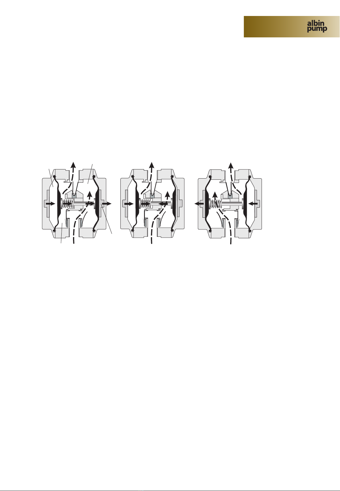
Inside the pump two diaphragms are separating the pumped liquid from the air supply.
When a diaphragm ruptures uid may be expelled through the air exhaust port. If dangerous liquids
are handled always connect the air exhaust port with a suitable container in a safe location. When the
product source is at a higher level than the pump (ooded suction), the exhaust should be piped to a
higher level than the product to prevent spills caused by siphoning.
Never operate a pump that is leaking, damaged, corroded or otherwise unable to contain the internal
uid or air pressure.
Never exceed the recommended service and inspection intervals for the diaphragms and air motor
parts.
Never put your face or body near the pump air exhaust while the pump is operating.
Always shut off the air supply and disconnect it from the pump before making repairs to the pump.
Be sure to relief all pressure from the discharge and suction pipes/hoses prior to disconnecting the
pump from the system.
Static electricity can be created when the pump is operating. Always use conductive polypropyl-
ene pumps in hazardous environments or for ammable uids. Pumps must be properly grounded.
Strictly follow the local safety regulations for hazardous environments.
AD Instruction Manual-2011EE-GB.indd 5 25/07/11 09:45

6
AD
since 1928
AD
since 1928
IMPORTANT !
The pump must not be used for other purposes than recommended and quoted for without consult-
ing your AlLBIN PUMP distributor.
Never use, under no circumstances, the pumps for pumping non-conductive ammable or explosive
uids.
The AD pumps do not exceed a noise level rating of 80 dB(A) but still it is advised always to wear ear
protection when you are working or standing close to an operating AODD pump. Noise can be sub-
stantially reduced by leading the exhaust air away through a hose connected to the air exhaust port.
Always wear suitable safety clothing when handling the pump.
Install shut-off valves on both side of the pump to be able to shut off the in- and outlet before service
and maintenance. Check to see that the pump can be drained without injuring anyone and without
damaging the environment or nearby equipment.
Always install a separate shut-off valve for the air supply easily accessible for manoeuvring.
Pressure variations may cause vibrations in the piping systems. Connect the pump to the pipes via
flexible coupling/hoses. Ensure that the pipes/fittings are securely bolted to the foundation.
Improper installation can cause fatal injuries.
If the pump handles liquids hazardous for person or environment, some sort of collector must be in-
stalled into which leakage can be led.
If the surface temperature of the system or parts of the system exceeds 60°C, these areas must be
marked with warning text reading ‘‘Hot surface’’ to avoid burns.
Never use other compressed gases than air to operate the pump.
Before starting the pump always make sure that the discharge point of the piping system is clear and
safe and that all persons have been warned to stand clear.
Always check the flow direction prior to start-up.
AD Instruction Manual-2011EE-GB.indd 6 25/07/11 09:45

7
AD
since 1928
AD since 1928
1.4 - OPERATING PRINCIPLE
The AODD pump is an air-powered, reciprocating positive displacement pump with two pumping chambers.
Two diaphragms, centrally located in the chambers, separate the compressed air (‘‘dry side’’) from the liquid
being pumped (‘‘wet side’’). A shaft connects the two diaphragms to each other.
A valve (air motor) distributes the air from one chamber to the other alternately, thus a reciprocating move-
ment of the diaphragms is created. At each stroke liquid is displaced by one of the diaphragms while the
opposite diaphragm sucks new liquid into the expanding chamber. Check valves, two on the discharge side
and two on the suction side, control and direct the liquid ow.
1.4.1 - OPERATING PRINCIPLE FOR THE AD PUMP
Compressed air enters the air chamber (a) on the left side of the pump. The diaphragms are pushed to the
right and liquid is displaced from chamber (A). Simultaneously pressure is reduced in chamber (B) and new
liquid enters. Used air is pushed out from the right air chamber (b).
Note the short ow path through the centre of the pump and how the check valves are opening and closing.
In the AD pump the diaphragms are not xed to the shaft. Thanks to this Flexible Diaphragm Suspension
(FDS-invention) and the spring at the shaft end, the diaphragms can move a short distance independently
of each other. At the end of each stroke both diaphragms are exposed to compressed air for a very short
period. When the left diaphragm has come to the end position, the right one has already started to move
back to the left and the spring is compressed. Thereafter the left diaphragm starts to move to the left and
the spring expands.
The two diaphragms are overlapping each other and thus there is no complete dead end at the same mo-
ment - pulsation is reduced.
This operating principle requires an extremely short reversing time of the compressed air.
The traditional sliding air valve could not be used and a new low friction air motor (FPV-invention - Friction-
less Pivoting Valve) with a rocking motion was developed. The new air motor is nothing less than a patented
sensation - extremely simple with very few parts and completely insensitive to the quality of the compressed
air.
The cycle is completed and the two diaphragms are now moving back to the left.
B
b
A
a
AD Instruction Manual-2011EE-GB.indd 7 25/07/11 09:45

8
AD
since 1928
AD
since 1928
1.5 - MODEL SPECIFICATION
Example : AD 0015 PX T
1. Family name
AD
2. Pump size
15, 30, 60, 120
3. Pump housing material
AL = Aluminium
AX = Aluminium Atex (EX)
PP = Polypropylene
PX = Polypropylene Conductive Atex (EX)
SS = Stainless Steel 316L
4. Diaphragm material
T = TEFLON (PTFE with EPDM carrier)
1.6 - STANDART PARTS
17
7
5
1
14
15
13
9
11
12
4
8
10
3
2
16
2
18
1. Pump housing
2. Lid
3. Diaphragm
4. Air motor
5. Shaft
(6. Shaft spring) option
7. Shaft bushing
8. Insert Inlet
9. CEG lockring Inlet
10. Air motor gasket external
11. Mufer Standard
12. CEG lockring Outlet
13. Chechvalve inlet
14. Checkvalve Outlet
15. Checkvalve Retainer
16. Foot plate
17. Cap nuts
18. Hexagon screws
AD Instruction Manual-2011EE-GB.indd 8 25/07/11 09:45

9
AD
since 1928
AD since 1928
2/ TECHNICAL INFORMATION
2.1 - TECHNICAL DATA
2.2 - MATERIAL SPECIFICATION
N.B : The comparison of standards is not 100% correct but is the closest possible from each standard.
* AA is a standard published by the Aluminum Association. The standard follows the “Registration Record of
International Alloy Designations”.
Wetted parts Material AISI DIN
Pump housing PP (Polypropylene) or Aluminium (AA6082) * 3.2315
Shaft bushing PPS (Tedur) 40% glass
Shaft Stainless steel 316 1.4436
Spring Stainless steel 316 1.4401
Check valve retainer 30 / 60 PPS (Tedur) 40% glass
Check valve retainer 120 Stainless steel 316 1.4436
Check valve (in- and out) PEEK
O-ring Teon (PTFE)
Screw Stainless steel 316 1.4436
Nut Stainless steel 316 1.4436
Diaphragm Teon (PTFE)
Diaphragm plate Stainless steel 316 1.4436
Size 15 30 60 120
Port size 1/4” 3/8” 3/4” 1.1/4”
Nominal max capacity (l/min) 20 35 80 130
Max pump pressure (bar) 7 7 7 7
Max air pressure (bar) 7 7 7 7
Max suction lift dry (m) 3 3 5 5
Max suction lift wet (m) 8 8 8 8
Max size of solids (mm) 4 4 5 5
Weight, version PP/Al (kg) 2.5 / 3.7 2.5 / 3.7 3.6 / 4.9 6.9 / 9.8
AD Instruction Manual-2011EE-GB.indd 9 25/07/11 09:45

10
AD
since 1928
AD
since 1928
2.1 - MATERIEL SPECIFICATION (CONT’D)
Size Material AISI DIN SS
Air outlet seal NBR (nitrile)
Diaphragm EPDM
Diaphragm plate Stainless steel 316 1.4436 2343
Washer PA polyamide
Side cover Aluminium not known not known 4253
Plunge PA polyamide
Ball seat PA polyamide
Ball NBR (nitrile)
Air motor housing Aluminium (AA6082)* 3.2315 4212
Cover Aluminium (AA6082)* 3.2315 4212
Air connection Aluminium (AA6082)* 3.2315 4212
Air manifold Aluminium (AA6082)* 3.2315 4212
Motor pivot Stainless steel 303 1.4305 2346
Pivot air seals in- and outlet NBR/ Stainless steel 304 1.4301 2332
Air gaskets NBR (nitrile)
Mufer HDPE (polyethylene)
Air O-rings NBR (nitrile)
Externals Material AISI DIN SS
Foot plate Stainless steel 304 1.4301 2333
Rubber foot NBR (nitrile)
Screw Stainless steel 304 1.4301 2333
Stud bolt Stainless steel 304 1.4301 2333
Cap nut Stainless steel 304 1.4301 2333
Screw Stainless steel 304 1.4301 2333
N.B : The comparison of standards is not 100% correct but is the closest possible from each standard.
* AA is a standard published by the Aluminum Association. The standard follows the “Registration Record of
International Alloy Designations”.
N.B : The comparison of standards is not 100% correct but is the closest possible from each standard.
AD Instruction Manual-2011EE-GB.indd 10 25/07/11 09:45

11
AD
since 1928
AD since 1928
2.3 - TEMPERATURE LIMITATIONS
Do not exceed the recommended operating temperatures of the pump. The maximum temperature limitations
are based on mechanical stress only and various liquids/chemical may reduce the maximum safe operating
temperatures of the pumps.
Diaphragms : PTFE can operate continuously between -30°C and +85ºC.
Pump housing : PP (polypropylene) can be used in the interval ±0°C and +85°C.
Aluminium can be used in the same interval as the diaphragms.
2.4 - SOUND LEVEL RATINGS
The following values were measured from an AD60, pumping water at 7 bar air pressure and fully open inlet
and discharge ports.The readings were made at a distance of 1 (one) metre on the same level as the pump :
• Front 79.5 dB(A)
• Left 75.5 dB(A)
• Right 74.9 dB(A)
• Behind 72.6 dB(A)
2.5 - DRY RUNNING
The AD-pump can normally run dry without damaging the pump components. For extended periods of dry
running, however, a certain wear of the shaft bushing will occur.
2.6 - REST VOLUMES
If the pump runs until it has emptied the suction line the following rest volumes will remain in the pumps :
• AD15 45 ml
• AD30 45 ml
• AD60 90 ml
• AD120 200 ml
If the product discharge line is closed the following volumes will remain in the pump :
• AD15 90 ml
• AD30 90 ml
• AD60 180 ml
• AD120 400 ml
AD Instruction Manual-2011EE-GB.indd 11 25/07/11 09:45

12
AD
since 1928
AD
since 1928
2/ PUMP PERFORMANCE CURVES
N.B : All curves are based on water discharge capacity at 20°C at 0 m suction head.
- To compensate for higher viscosity use the curve “3.2.1 Reduction for viscosity”.
- To compensate for a negative suction head use the curve “3.2.2 Reduction for suction lift”.
Important ! To obtain a long diaphragm life and a high efciency (low air consumption) always select a
pump which has a max capacity which is as least 1,5 times higher than the desired ow rate.
Caution ! Do not exceed 7 bar air supply or liquid pump pressure.
3.1 - NOMINAL CAPACITY AD RANGE
Discharge Pressure (bar)
020406080 100 120
6
5
4
3
2
1
0
Fluid flow (lpm)
AD15 AD30 AD60 AD120
AD Instruction Manual-2011EE-GB.indd 12 25/07/11 09:45

13
AD
since 1928
AD since 1928
3.2 - HOW TO USE THE PERFORMANCE CURVES
Example : AD60 - 30 l/minute against a discharge pressure of 2.0 bar.
Pump selection
Find the required ow (30 l/min) along the horizontal axis. Go vertical to the intersection with 2 bar uid
outlet and read the air pressure required, ~ 3,5 bar.
Air consumption
Again - nd the required ow (30 l/min) along the horizontal axis. Go vertical to the intersection with the
required air pressure (3,5 bar) and read the air consumption to the left.
In the example, ~ 180 l/min.
Fluid ow (lpm)
0
50
100
150
200
250
300
350
400
450
0102030405060708
09
0
A
B
C
180 l/min
Air consumption (lpm)
0
1
2
3
4
5
6
7
0102030405060708
09
0
A
B
C
~ 3.5 bar
1
2
Fluid ow (lpm)
Air consumption (lpm)
A) 6 bar air pressure (87 psi)
B) 4 bar air pressure (58 psi)
C) 2 bar air pressure (29 psi)
AD Instruction Manual-2011EE-GB.indd 13 25/07/11 09:46

14
AD
since 1928
AD
since 1928
3.2.1 - REDUCTION FOR VISCOSITY AD15 - AD120
3.2.2 - REDUCTION FOR SUCTION LIFT AD15 - AD120
Viscosity (cP)
0
10
20
30
40
50
60
70
80
90
100
0 500 1000 1500 2000 2500 3000 3500
Capacity reduction (%)
Suction lift (m)
0
10
20
30
40
50
60
70
80
90
100
0246810
Capacity decrease (%)
AD Instruction Manual-2011EE-GB.indd 14 25/07/11 09:46

15
AD
since 1928
AD since 1928
3.3 - AD15
Flow & Air consumption
0
1
2
3
4
5
6
7
0510 15 20 25 30 35 40
A
B
C
Fluid outlet pressure (Bar)
Fluid ow (lpm)
Flow / Pressure
A) 6 bar air pressure (87 psi)
B) 4 bar air pressure (58 psi)
C) 2 bar air pressure (29 psi)
0
50
100
150
200
250
300
350
0510 15 20 25 30 35 40 45
A
B
C
Air consumption (lpm)
Fluid ow (lpm)
A) 6 bar air pressure (87 psi)
B) 4 bar air pressure (58 psi)
C) 2 bar air pressure (29 psi)
AD Instruction Manual-2011EE-GB.indd 15 25/07/11 09:46

16
AD
since 1928
AD
since 1928
3.4 - AD30
0
1
2
3
4
5
6
7
0510 15 20 25 30 35 40
A
B
C
Fluid outlet pressure (Bar)
Fluid ow (lpm)
Flow / Pressure
A) 6 bar air pressure (87 psi)
B) 4 bar air pressure (58 psi)
C) 2 bar air pressure (29 psi)
0
50
100
150
200
250
300
350
0510 15 20 25 30 35 40 45
A
B
C
Air consumption (lpm)
Fluid ow (lpm)
Flow & Air consumption
A) 6 bar air pressure (87 psi)
B) 4 bar air pressure (58 psi)
C) 2 bar air pressure (29 psi)
AD Instruction Manual-2011EE-GB.indd 16 25/07/11 09:46

17
AD
since 1928
AD since 1928
3.5 - AD60
Flow / Pressure
Flow & Air consumption
0
1
2
3
4
5
6
7
0102030405060708
09
0
A
B
C
Fluid outlet pressure (Bar)
Fluid ow (lpm)
A) 6 bar air pressure (87 psi)
B) 4 bar air pressure (58 psi)
C) 2 bar air pressure (29 psi)
0
50
100
150
200
250
300
350
400
450
0102030405060708
09
0
A
B
C
Air consumption (lpm)
Fluid ow (lpm)
A) 6 bar air pressure (87 psi)
B) 4 bar air pressure (58 psi)
C) 2 bar air pressure (29 psi)
AD Instruction Manual-2011EE-GB.indd 17 25/07/11 09:46

18
AD
since 1928
AD
since 1928
3.6 - AD120
Flow & Air consumption
0
50
100
150
200
250
300
350
400
450
500
020406080 100 120 140
A
B
C
Air consumption (lpm)
Fluid ow (lpm)
A) 6 bar air pressure (87 psi)
B) 4 bar air pressure (58 psi)
C) 2 bar air pressure (29 psi)
0
1
2
3
4
5
6
7
020406080 100 120 140
A
B
C
Fluid outlet pressure (Bar)
Fluid ow (lpm)
Flow / Pressure
A) 6 bar air pressure (87 psi)
B) 4 bar air pressure (58 psi)
C) 2 bar air pressure (29 psi)
AD Instruction Manual-2011EE-GB.indd 18 25/07/11 09:46

19
AD
since 1928
AD since 1928
Filter /
Regulator Flexible pipe
Muffler
Fluid discharge >10 mm
inner diameter.
Shut-off valve
Pressure gauge
Flexible connection
Vacuum meter
Shut-off valve
Shut-off valve
Air supply
Fluid suction
4 / INSTALLATION
4.1 - SYSTEM DESIGN AND INSTALLATION
For the air connections, use an oversize air line of minimum 10 mm diameter.
When a pump is to be incorporated in a system, it is good practice to, as far as possible, minimise the length
of the pipes/hoses and the number of ttings (tees, unions, bends, etc.) and restrictions.
When designing the suction lines, particular care should be taken. These should be as short and straight as possible, us-
ing a minimum of ttings to optimise a good product ow to the pump. Use a reinforced, non-collapsible hose of at least
the same inner diameter as the suction port.
Always consider the following when designing a system : make sure that there is enough room provided
around the pump to allow for routine service work, i.e. to dismantle the covers to inspect or change the
diaphragms and check valves. The Liquid Flow comes with a stainless steel foot plate and rubber feet.
For security reasons it is recommended to bolt the pump to a base.
Thanks to the ap valves the pump can be mounted upside-down, sideways or on any of its 360-degree axis
(see illustration).
Filter /
Regulator Flexible pipe
Muffler
Fluid discharge >10 mm
inner diameter.
Shut-off valve
Pressure gauge
Flexible connection
Vacuum meter
Shut-off valve
Shut-off valve
A
ir supply
Fluid suction
AD Instruction Manual-2011EE-GB.indd 19 25/07/11 09:46

20
AD
since 1928
AD
since 1928
The AD pump should be attached to the plant piping using a exible hose/coupling on both the intake and
discharge ports of the pump. The pump must not be used to support the pipelines.
All pipe work to and from the pump must be independently supported otherwise there is a risk of distortion of the
pump components. The suction pipe or hose should be at least the diameter of the pump’s inlet port or larger
if a highly viscous product is being pumped. The suction hose must be of a reinforced, non-collapsible type.
By tting an over-dimensioned (2 times the diameter of the pump discharge) exible hose to the discharge,
vibrations and/or pulsation are reduced to a minimum in the system.
The hose should be 2 - 2.5 m long and can be arranged in a loop. The discharge piping should also be at least
the same diameter as the pump port. By increasing the diameter of the piping the friction losses decrease.
Before using the pump for the rst time, all external screws and nuts should be checked to match the given
torque specications – see picture. It is advised to check the fasteners after one day of operation and there-
after every two - three months.
10 Nm
(4 hexagon screws, 6 mm)
22 Nm
(8 cap nuts)
It is recommended to use a compatible, liquid sealant on all male threads. Be sure to tighten all connections
rmly to avoid air or uid leakage.
The AD can only pump in one direction and the uid inlet is below the name plate.
The arrow on the name plate shows the ow direction. The air and liquid ow is in the same direction.
Thanks to the ingenious design of the air motor (FPV - Frictionless Pivoting Valve) any type of air can be
used - dry or oily, clean or dirty. Still it is recommended to install a lter/regulator combination.
AD Instruction Manual-2011EE-GB.indd 20 25/07/11 09:46
This manual suits for next models
3
Table of contents
Other ALBIN PUMP Water Pump manuals
Popular Water Pump manuals by other brands

Clarke
Clarke BPT600 Operating & maintenance instructions

ITT
ITT GOULDS PUMPS LF 3196 i-FRAME Installation, operation and maintenance manual

Zoeller
Zoeller SHARK 800 Series owner's manual

Jesco
Jesco MIDIDOS E Operation & maintenance instructions

Crane
Crane Deming BAF-8 installation manual

Profi-pumpe
Profi-pumpe INVERT-TECH 2 operating instructions