ALBIN PUMP ALH User manual

ALBIN PUMP ALH
Hose Pumps / Instruction Manual
since 1928

2[email protected] Albinpump.com Albin Pump ALH Instruction Manual
since 1928
1 | HOW TO USE THIS MAINTENANCE MANUAL .................................... 4
2 | PUMP USE AND TRAINING .................................................. 4
2.1 - Use of the pump ....................................................4
2.2 - Responsibility ......................................................4
2.3 - Training and instructions..............................................4
3 | DESCRIPTION ............................................................. 5
3.1 - Product identication ................................................5
3.2 - Operation principle ..................................................5
3.3 - Pump construction ..................................................6
3.3.1 - Pumps ALH05 to ALH20 .........................................6
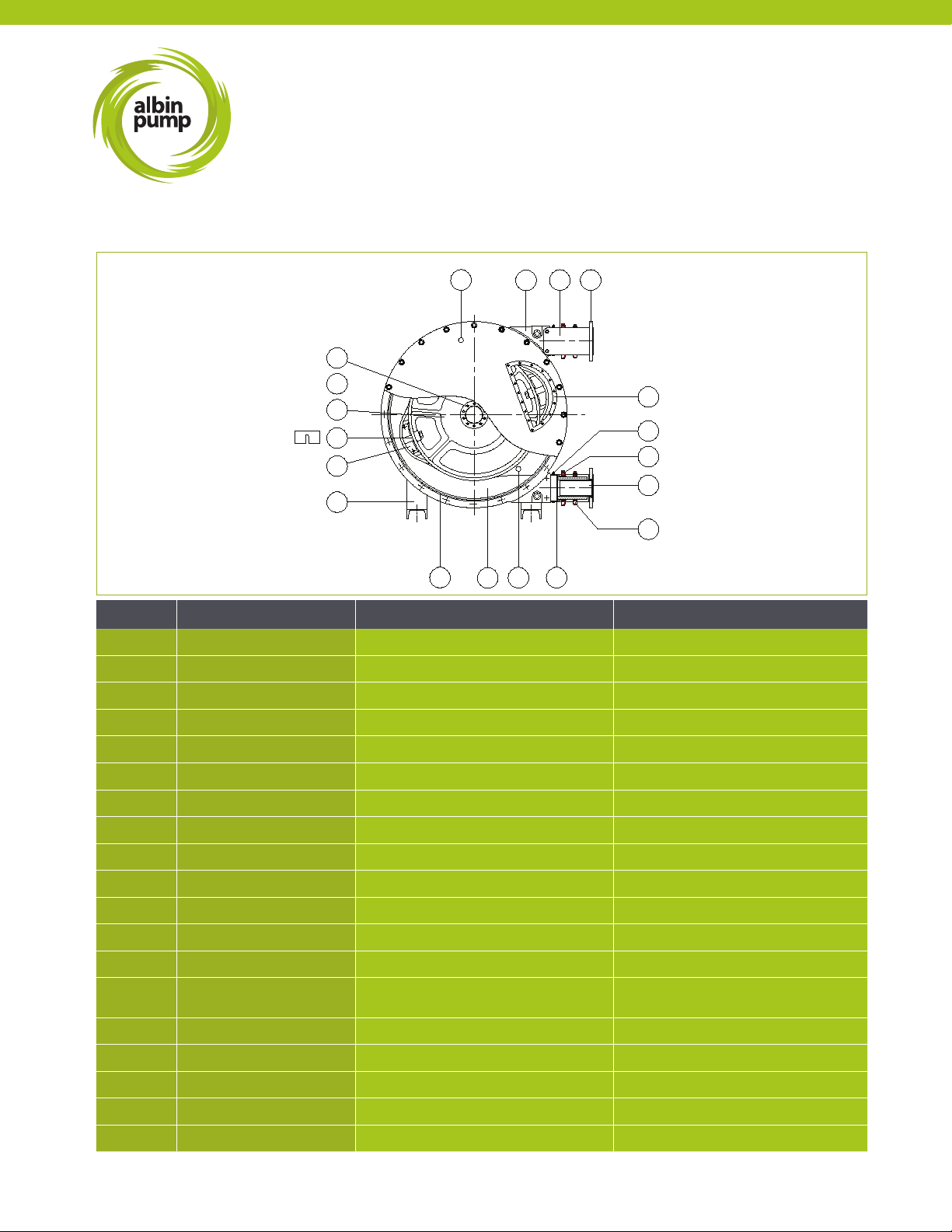
3.3.2 - Pumps ALH25 to ALH65 .........................................7
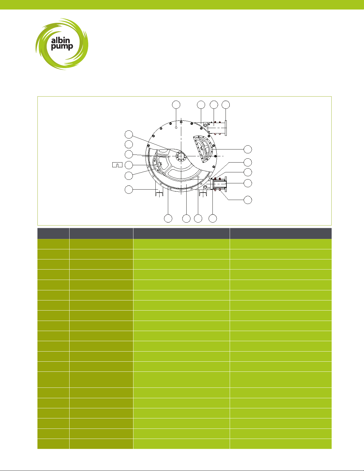
3.3.3 - Pumps ALH80 to ALH125 ........................................8
3.4 - Pump hose ........................................................9
3.5 - Pump gearbox .....................................................9
3.6 - Electrical Motor.....................................................9
3.7 - Available Options ...................................................9
4 | INSTALLATION .............................................................10
4.1 - Unpacking and control ..............................................10
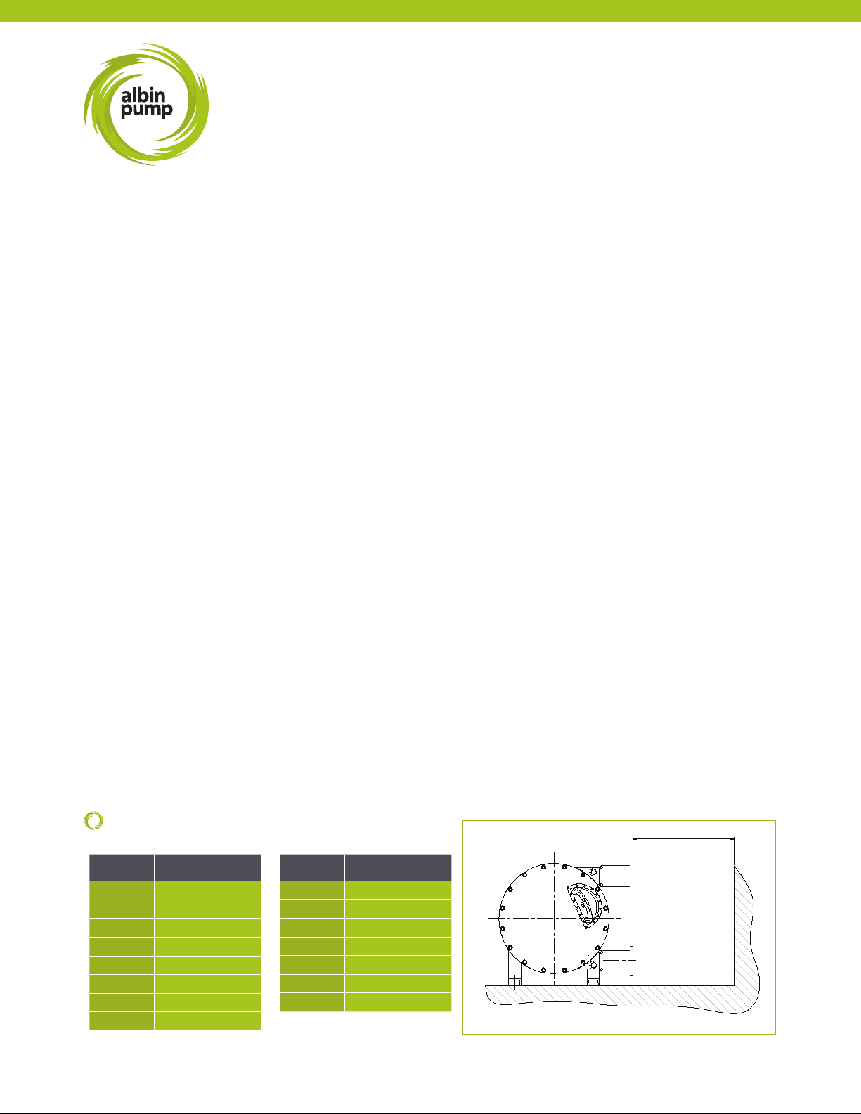
4.2 - Conditions of installation ............................................10
4.3 - Setup ...........................................................10
4.4 - Piping ...........................................................10
4.5 - Pump lifting.......................................................11
5 | PUMP START-UP. . . . . . . . . . . . . . . . . . . . . . . . . . . . . . . . . . . . . . . . . . . . . . . . . . . . . . . . . . . 11
5.1 - Preparations ......................................................11
5.2 - Pump start-up.....................................................11
6 | MAINTENANCE ............................................................11
6.1 - Emptying and lling of the lubricant ....................................11
6.2 - Hose cleaning .....................................................13
6.3 - Hose replacement. . . . . . . . . . . . . . . . . . . . . . . . . . . . . . . . . . . . . . . . . . . . . . . . . . 13
6.3.1 - Removing the hose ............................................13
6.3.2 - Cleaning of the pump casing ....................................15
6.3.3 - Reassembly of the hose ........................................15
6.4 - Replacement of spare parts ..........................................17
6.4.1 - Replacement of pump shoes (except ALH05, ALH10, ALH15, ALH20) ....17
6.4.2 - Replacement of the seal ring (REF 27) and the shaft seal (REF 26) .......18
6.5 - Shoe shimming....................................................21
6.6 - Maintenance and periodical controls ...................................22
6.7 - ALHS series complementary information ................................23
6.7.1 - Set up ......................................................23
6.7.2 - Pump starting ................................................23
6.7.3 - Bearing case dismantling and lip seal (REF 26) replacement ............23
6.7.4 - Maintenance and periodical controls .............................. 23
ALH
Table of Contents

Albin Pump ALH Instruction Manual Albinpump.com [email protected] 3
since 1928
7 | STORAGE ................................................................23
7.1 - Pump storage .....................................................23
7.2 - Hose storage .....................................................24
8 | TROUBLESHOOTING.......................................................24
9 | CHARACTERISTICS AND TECHNICAL SPECIFICATIONS............................ 26
9.1 - Performances curves ...............................................26
9.2 - Overall dimensions .................................................29
9.3 - Nomenclature .....................................................33
9.4 - ALH Spare parts list ................................................43
9.5 - ALHS Bearing case parts list .........................................46
9.6 - Hose rupture and vacuum system parts list..............................46
9.7 - Lubrication table...................................................47
9.8 - Shoe shimming table ...............................................47
9.9 - Generated noise and temperature .....................................48
9.10 - Expansible hub assembly and disassembly: generalities ..................49
9.11 - Torque..........................................................50
9.12 - Weight..........................................................51
10 | COMPLEMENTARY INSTRUCTIONS FOR ATEX CERTIFIED MATERIAL ................52
11 | SECURITY FORM..........................................................60
12 | STATEMENT OF CE COMPLIANCE ............................................61
ALH
Table of Contents

4[email protected] Albinpump.com Albin Pump ALH Instruction Manual
since 1928
ALH
Manual Usage / Security and Guarantees
1 | HOW TO USE THIS MAINTENANCE MANUAL
This manual is specic to ALBIN PUMP SAS (ALBIN PUMP) ALH series peristaltic pumps. It allows the users to install, to start
and to carry out maintenance on these pumps. All persons, tters and users must read this maintenance manual in its entirety.
Documents concerning the gearbox, the electrical motors, as well as all other options (hose rupture detector, etc.) are provided in
annex. Refer to the applicable section in this document to understand specic details regarding that component.
Your local ALBIN distributor can be contacted regarding information not contained in this manual. For a quicker reply, please provide the
following information:
- Type of pump
- Pump serial number
- Reference of order
You can also visit our website albinpump.com for further information.
2 | PUMP USE AND TRAINING
2.1 - USE OF THE PUMP
The pump was dened for a specic application. Any other use which does not comply with envisaged use is not guaranteed.
ALBIN PUMP cannot be held responsible for damage or possible wounds / injuries produced during the use of the pump. The
pump was designed in accordance with EU norms and applicable directives. Use the pump for applications that have been
approved by the appropriate ALBIN personnel or distributors. If you want to change your application, rst contact your ALBIN
PUMP distributor.
2.2 - RESPONSIBILITY
ALBIN PUMP is not responsible for damage or wounds / injuries caused by mishandling of products, disregard of security
directives and maintenance instructions contained in this manual, or by negligence during the installation, use, service, or repair of
ALBIN hose pumps. Moreover, additional directives of security can be necessary according to working conditions or according
process. Contact your ALBIN PUMP distributor if you notice a potential danger during the use of the pump.
2.3 - TRAINING OF THE USER AND INSTRUCTIONS
Every person who installs, uses or performs any operations of maintenance on the pump must be qualied and must have
previously read this technical manual. Any temporary personnel must be supervised by skilled users.
The order of execution of operations dened in this manual must be absolutely respected. Store this manual next to the pump so
that it can be consulted at any time.

Albin Pump ALH Instruction Manual Albinpump.com [email protected] 5
since 1928
ALH
Description
3 | DESCRIPTION
3.1 - IDENTIFICATION OF THE PUMP
ALBIN PUMPS are identiable by the pump plate located on the frame. The plate includes the pump type and serial number of the
pump. This serial number leads to all information concerning building materials, nature of the hose, characteristics of the gearbox
and characteristics of the motor. The gearbox and motor have their own descriptive plate that states the reduction ratio, power,
and electrical voltage.
3.2 - OPERATION PRINCIPLE
PHASE 3
As soon as, at the discharge side, the shoe is detached
from the hose, the other shoe diametrically opposite is
already in compression thus avoiding an internal product
leakage. The product is then successively sucked and
pushed due to the wheel rotation.
PHASE 2
The pumped liquid has now entered the hose. The
second shoe will compress the hose and push the liquid
towards the pump outlet.
PHASE 1
The pump hose is compressed successively by two
pressing shoes assembled on a rotating wheel. The rst
shoe, by pressing the walls of the hose, will create a
vacuum and attract the pumped liquid into the hose.

6[email protected] Albinpump.com Albin Pump ALH Instruction Manual
since 1928
ALH
Description
2 1 18
19
3
21
10 16 14 6
12
9
8
7
71
1812
614
1610
21
3
19
12
9
8
7
Part No DESIGNATION ALH05 - 10 ALH15-20
1CASING CAST IRON CAST IRON
2 COVER POLYCARBONATE POLYCARBONATE
3 WHEEL CAST IRON CAST IRON
6 SLEEVE EPDM EPDM
7CLAMP ON CASING STAINLESS STEEL STAINLESS STEEL
8CLAMP SLEEVE / HOSE BICHROMATED STEEL BICHROMATED STEEL
9 CLAMP ON HOSE BICHROMATED STEEL BICHROMATED STEEL
10 SEAL COVER NITRILE NITRILE
12 INSERT STAINLESS STEEL / PPH / PVDF STAINLESS STEEL / PPH / PVDF
14 LUBRICANT GLYCERIN BLEND GLYCERIN BLEND
16 HOSE NR / NBR / EPDM / NBR FOOD / VITON
®
/
HYPALON
®
/ NR-FOOD
NR / NBR / EPDM / NBR FOOD / VITON
®
/
HYPALON
®
/ NR-FOOD
18 BRACKET ELECTROPLATED STEEL ELECTROPLATED STEEL
19 HUB STEEL STEEL
21 FRAME ELECTROPLATED STEEL ELECTROPLATED STEEL
71 COVER FLANGE ELECTROPLATED STEEL WITHOUT FLANGE
PUMP ALH15 - ALH20 PUMP ALH05 - ALH10
3.3 - PUMP CONSTRUCTION
3.3.1 - PUMPS ALH05 TO ALH20

Albin Pump ALH Instruction Manual Albinpump.com [email protected] 7
since 1928
ALH
Description
3.3.2 - PUMPS ALH25 TO ALH65
18 47
15
7
8
12
9
6
14
16
21
10
4
20
19
1
2
3
5
Part No DESIGNATION ALH25 - 32 - 40 ALHX40 - ALH50 - 65 - ALHX65
1CASING DUCTILE CAST IRON DUCTILE CAST IRON
2 COVER ELECTROPLATED STEEL STEEL
3 WHEEL DUCTILE CAST IRON DUCTILE CAST IRON
4SHIM GALVANIZED STEEL GALVANIZED STEEL
5 SHOE CAST IRON CAST IRON
6 SLEEVE EPDM EPDM
7CLAMP ON CASING STAINLESS STEEL STAINLESS STEEL
8CLAMP SLEEVE / HOSE STAINLESS STEEL STAINLESS STEEL
9 CLAMP ON HOSE STAINLESS STEEL BICHROMATE STEEL
10 SEAL COVER NITRILE NITRILE
12 INSERT STAINLESS STEEL / PPH / PVDF STAINLESS STEEL / PPH / PVDF
14 LUBRICANT GLYCERIN BLEND GLYCERIN BLEND
15 SIGHT GLASS SEAL POLYCARBONATE POLYCARBONATE
16 HOSE NR / NBR / EPDM / NBR FOOD / VITON
®
/
HYPALON
®
/ NR-FOOD
NR / NBR / EPDM / NBR FOOD / VITON
®
/
HYPALON
®
/ NR-FOOD
18 BRACKET ELECTROPLATED STEEL ELECTROPLATED STEEL
19 HUB STEEL STEEL
21 FRAME STEEL STEEL
46 SIGHT GLASS SEAL NITRILE NITRILE
47 INLET/OUTLET FLANGE STAINLESS STEEL STAINLESS STEEL

8[email protected] Albinpump.com Albin Pump ALH Instruction Manual
since 1928
ALH
Description
3.3.3 - PUMPS ALHX80 TO ALH125
18 47
15
7
8
12
9
6
14
16
21
10
4
20
19
1
2
3
5
Part No DESIGNATION ALHX80 - ALH80 ALH100 - ALH125
1CASING DUCTILE CAST IRON DUCTILE CAST IRON
2 COVER STEEL STEEL
3 WHEEL DUCTILE CAST IRON DUCTILE CAST IRON
4SHIM GALVANIZED STEEL GALVANIZED STEEL
5 SHOE DUCTILE CAST IRON DUCTILE CAST IRON
6 SLEEVE EPDM EPDM
7CLAMP ON CASING STAINLESS STEEL STAINLESS STEEL
8CLAMP SLEEVE / HOSE STAINLESS STEEL STAINLESS STEEL
9 CLAMP ON HOSE BICHROMATE STEEL BICHROMATE STEEL
10 SEAL COVER NITRILE NITRILE
12 INSERT STAINLESS STEEL / PPH / PVDF STAINLESS STEEL / PPH / PVDF
14 LUBRICANT GLYCERIN BLEND GLYCERIN BLEND
15 SIGHT GLASS POLYCARBONATE POLYCARBONATE
16 HOSE NR / NBR / EPDM / NBR FOOD / VITON
®
/
HYPALON
®
/ NR-Food
NR / NBR / EPDM / NBR FOOD / VITON
®
/
HYPALON
®
/ NR-Food
18 BRACKET ELECTROPLATED STEEL ELECTROPLATED STEEL
19 HUB STEEL
20 BOLT ON PLATE DUCTILE CAST IRON
21 FRAME STEEL STEEL
46 SIGHT GLASS SEAL NITRILE NITRILE
47 INLET/OUTLET FLANGE STAINLESS STEEL STAINLESS STEEL

Albin Pump ALH Instruction Manual Albinpump.com [email protected] 9
since 1928
ALH
Description
3.4 - HOSE
The ALBIN hoses are manufactured according to very strict specications to acquire the best performances of the pump and to
assure an optimum hose life. They are available in six materials: Natural Rubber (NR), perbunan (NBR), EPDM, NBR food, Viton®,
and Hypalon®. The material of the hose must be compatible with the pumped liquid. Consult an ALBIN PUMP distributor to dene
the best hose for your process or consult the chemical resistance table on our website albinpump.com.
HOSE DIMENSIONS
mm (Inch)
PUMP Ø INSIDE THICKNESS LENGTH
ALH05 5 (0.2) 13.5 (0.5) 570 (22.4)
ALH10 10 (0.4) 11 (0.4) 570 (22.4)
ALH15 15 (0.6) 11 (0.4) 830 (32.7)
ALH20 20 (0.8) 9 (0.3) 830 (32.7)
ALH25 25 (1) 14.5 (0.6) 1090 (42.9)
ALH32 32 (1.2) 15.5 (0.6) 1300 (51.2)
ALH40 38 (1.5) 13.5 (0.5) 1300 (51.2)
ALHX40 40 (1.6) 13.5 (0.5) 1500 (59.1)
ALH50 51 (2) 15 (0.6) 1820 (71.7)
ALH65 60 (2.4) 13.5 (0.5) 1850 (72.8)
ALHX65 65 (2.5) 17.5 (0.7) 2075 (81.6)
ALHX80 80 (3.1) 17.5 (0.7) 2400 (94.5)
ALH80 80 (3.1) 21.5 (0.8) 2910 (114.5)
ALH100 100 (3.9) 22 (0.9) 3410 (134.2)
ALH125 125 (4.9) 21.25 (0.8) 4000 (157.4)
3.5 - GEAR BOX
Our standard gearboxes are coaxial gearboxes for pumps ALH05 to ALHX40 and planetary for pumps ALH50 to ALH100. ALH125
can be equipped with both. They have been sized according to the important radial loads of the pump. Consult the gearbox
maintenance manual provided with the pump to know the quantity of lubricant requested as well as the periodicity of oil change.
3.6 - ELECTRICAL MOTORS
The standard motors provided on our pumps are squirrel-cage motors and have a 230/400 V and 400/690 V 50/60 Hz three-phase
voltage. Voltage is dependent on the selected power supply. If the pump has to work in a potentially explosive environment, please
refer to the complementary information on ATEX compliances and contact your ALBIN PUMP distributor.
3.7 - AVAILABLE OPTIONS
ALBIN PUMP oers several options for their pumps:
- Hose rupture detector.
- Revolution-counter.
- Pulsation dampener.
- Air vacuum assistance (for highly viscous liquids).
- Variable speed drive.
- Mechanical variator.
Please contact your ALBIN PUMP distributor for any information about these dierent options
.

10 [email protected] Albinpump.com Albin Pump ALH Instruction Manual
since 1928
ALH
Installation
DIMENSIONS
mm (Inch)
4 | INSTALLATION
4.1 - UNPACKING AND CONTROL
During the receipt of the pump, please follow the instructions printed on the packing. Make a visual inspection to insure that no
damage occurred during shipment. If this is the case, please contact your ALBIN PUMP distributor as soon as possible.
4.2 - CONDITIONS OF USE
ALH pumps can work in atmospheres where the temperature is situated between -20°C (-4°F) and 45°C (113°F). Pumps are
coated with a 150µ paint which will protect them against certain aggressive environments. They are designed for indoor and
outdoor setup.
4.3 - SET UP
Before installing the pump, check the following points:
- The pump is delivered with a frame provided with four anchoring holes. It must be xed on a solid base with a slope which
does not exceed 5mm for 1m and must be rmly fastened to this one.
- Require enough space around the pump to carry out maintenance. If such was not possible, consider the moving of the pump
to a space provided for this purpose.
- Make sure that the room is adequately ventilated to relieve the heat generated by the pump. Leave a space behind the motor
ventilator hood so as not to obstruct air intake.
4.4 - PIPING
Suction line piping:
- The internal diameter of the piping must be equal to or greater than that of the pump hose,.
- It must be the shortest and most direct possible to avoid suction loss.
- Suction pressures at higher operating pressures may cause the pump to rotate when the pump is disengaged. Above 1 bar,
consider adding a suction line valve to prevent this occurrence.
- Limit the presence of bends and make sure that they are as large as possible.
- Make sure that piping can support the service pressure of the pump.
Discharge line piping:
-The internal diameter of piping must be equal to or greater than to that of the pump hose, see §3.4.
- It must be the shortest and most direct possible to avoid discharge pressure loss.
- Limit the presence of bends and make sure that they are as large as possible.
- Provide a space for a pulsation dampener (see picture below).
- If there is a valve on the discharge line, install a pressure relief valve or an over pressure protection gauge to avoid any
possible damage to the pump and to the installation.
- It is recommended to install a exible line to help absorb pulsation.
During the pump ground study, provide enough space for the hose change as well as the possible installation of a pulsation
dampener. Distance (L) is the required length for hose removal.
L
PUMP L
ALH05 400 (15.7)
ALH10 400 (15.7)
ALH15 500 (19.7)
ALH20 500 (19.7)
ALH25 800 (31.5)
ALH32 1000 (39.4)
ALH40 1000 (39.4)
ALHX40 1200 (47.2)
PUMP L
ALH50 1400 (55.1)
ALH65 1400 (55.1)
ALHX65 1500 (59.0)
ALHX80 1600 (63.0)
ALH80 2000 (78.7)
ALH100 2800 (110.2)
ALH125 3000 (118.1)

Albin Pump ALH Instruction Manual Albinpump.com [email protected] 11
since 1928
ALH
Installation / Pump Start-up / Maintenance
5 | PUMP START-UP
5.1 - PREPARATIONS
a. Connect the electrical motor in accordance with the local rules and regulations. Perform this work by qualied personnel.
b. Make sure that the lubricant level arrives at the level of the sight glass (see §9.7 for lubricant table and §6.1 for an
image). Add lubricant if required by the breather or by the sight glass, see §6.1 for instructions on emptying and lling
the lubricant.
c. Make sure the shimming of the pump is according to the pump process, see §6.5 shoe shimming. Refer
to §9.8 for shoe shimming tables.
d. Check the direction of rotation of the pump. It is recommended to install a rotation inverter on the motor for the hose
change.
5.2 - START-UP
a. Install piping at the inlet and outlet of the pump.
b. Make sure that valves at the inlet and outlet are opened.
c. Start the pump by checking its direction of rotation by the sight glass.
6 | MAINTENANCE
6.1 - EMPTYING AND FILLING OF THE LUBRICANT
Refer to §6.6 to know the periodicity of lubricant change.
1 - Stop the pump.
2 - Place a tray underneath the drain plug (REF 23).
REF 15 and 46
REF 23
4.5 - LIFTING THE PUMP
Pumps are provided with two lift holes (eyebolts) placed on the upper part of the frame. While lifting the pump, respect the
following points:
- Lift the complete hose pump using the lifting rings plus additional support on the gearbox and the motor using suitably
rated straps or slings.
- Never exceed the upper limits of lift and control the motorized pump weights in the table below.
- The motorized pump, given its centre of gravity, will tend to overbalance on the pump head side. Make sure that the
persons are at a secure distance from the pump to avoid any risk of wound.
- Never raise the pump otherwise than by the pump’s lifting rings.
- Never raise the pump by its orices nor by its brackets.
PUMP ALH05-10 ALH15 ALH20 ALH25 ALH32 ALH40 ALHX40
Approx. Weight 25 (55.1) 35 (77.2) 35 (77.2) 80 (176.4) 130 (286.6) 145 (319.7) 210 (463)
PUMP ALH50 ALH65 ALHX65 ALHX80 ALH80 ALH100 ALH125
Approx. Weight 315 (694.5) 335 (738.5) 500 (1102.3) 700 (1543) 930 (2050.3) 1250 (2755.8) 1750 (3858.1)
WEIGHT
kg (lbs)

12 [email protected] Albinpump.com Albin Pump ALH Instruction Manual
since 1928
ALH
Maintenance
3 - If necessary, install a tap and a drain circuit instead of the drain plug (REF 23).
4 - Make sure that this tray can contain the quantity of lubricant during the drainage process, see lubricant volume
table §9.7.
5 - Unscrew the plug (REF 23) and undertake emptying.
6 - Position and tighten the plug (REF 23) by applying PTFE band or waterproof paste or close the drain tap
.
NOTE : If the pump is mounted with the inlet/outlet positioned upwards, lubricant drainage is obtained by unscrewing cover
screws in the lower part.
7 - Remove the sight glass (REF 15) as well as its seal (REF 46) and ll the casing with the ALBIN lubricant, see lubricant
table §9.7. You can also ll the casing by the breather cap (REF 52) situated at the back of the pump casing. The
required lubricant level is underneath the bottom edge of the sight glass (see photo beneath).
8 - Check the state of the seal (REF 46) and reassemble the sight glass (REF 15) or tighten the breather cap (REF 52).
REF 52
MAX LEVEL
FOR MODELS ALH05, ALH10, ALH15
and ALH20:
Unscrew higher breather plug (REF 52) of the
pump. Place a funnel inside the plug hole and ll
the casing with the ALBIN lubricant
(see lubricant table §9.7). The necessary volume
of lubricant is just underneath the shaft line.

Albin Pump ALH Instruction Manual Albinpump.com [email protected] 13
since 1928
ALH
Maintenance
REF 8
REF 9
PHOTO 1
6.2 - HOSE CLEANING
The hose cleaning can be done without removing the hose. It can be done with water or with a cleaning liquid (check compatibility
with hose material). With numerous products, it is necessary to clean the hose after every pumping session in order to avoid the
hardening of the product inside this one.
CAUTION! Make sure that the cleaning liquid temperature is adapted to the hose material.
6.3 - HOSE REPLACEMENT
CAUTION! Before any hose change, check the following points:
a. This service has to be performed by skilled personnel that is acquainted with this manual.
b. Isolate the pump from the power supply. Inlet and outlet valves have to be closed to minimize product loss. The pump will
need to be re-connected power to expel and load in the hose in subsequent steps.
c. Always carry clothes and necessary protection according to the pumped product.
d. Respect all security and environmental rules necessary for the manipulation of the pumped product.
6.3.1 - HOSE REMOVAL
1 - Disconnect and remove the suction and discharge piping.
2 - Drain the lubricant as explained in §6.1.
3 - At the suction end, loosen clamps (REF 8 and 9) (photo 1).
Extract the insert (REF 12) and remove the ange (REF 47) (photo 2). The ange may require an additional tool (e.g. prybar)
to be removed, carefully, as to not damage the insert/ange. Remove the brackets REF 18 (photograph 3).
FOR MODELS ALH05, ALH10, ALH15 and ALH20:
Remove circlips using circlips pliers (REF 24) and dismantle bracket (REF 18). Extract insert (REF 12). Careful-
ly perform these actions to avoid damaging the ribbed ttings.
REF 47
REF 12
PHOTO 2
REF 8 REF 9
REF 24
PHOTO 3
REF 18

14 [email protected] Albinpump.com Albin Pump ALH Instruction Manual
since 1928
ALH
Maintenance
4 - At the discharge end, loosen clamps (REF 8 and 9). Extract the insert (REF 12) and remove the ange (REF 47) as well
as the brackets (REF 18) (photograph 7). Remove clamps (REF 8 and 9) (photograph 7).
5 - Jog run the motor to deliver the hose from the pump casing at the outlet side.
WARNING! The hose can come out of the pump casing very fast and cause harm.
Check that nobody is in front of the pump´s orices while removing the hose.
REF 47
REF 12
PHOTO 4 PHOTO 5 PHOTO 6
FOR MODELS ALH05, ALH10, ALH15
and ALH20:
At the pump outlet, loosen clamps (REF 8) and (REF 9).
Remove circlips (REF 24) and dismantle bracket REF
18. Extract insert (REF 12). Remove clamps (REF 8) and
(REF 9). Carefully perform these actions to avoid damag-
ing the ribbed ttings.
REF 8 REF 9
REF 24
REF 12REF 18
PHOTO 7

Albin Pump ALH Instruction Manual Albinpump.com [email protected] 15
since 1928
ALH
Maintenance
6.3.2 - PUMP CASING CLEANING
This operation is necessary when a hose has burst and when the product has contaminated the inside of the pump
casing. Perform these steps with caution. If hazardous chemicals were being pumped, use caution when removing the
lubricant.
1 - Unfasten cover screws by leaving two screws partly fastened to the casing. Slightly withdraw the cover from the
casing and x a shackle in one of the cover’s highest fastening holes (see picture below). Pumps ALH80, ALH100 and
ALH125 are equipped with a lifting ring. Install a lift equipment in this shackle and slightly raise the cover. Unfasten the
remaining screws and withdraw the cover. For cover weight please refer §9.12
2 - Check the state of the cover seal (REF 10) §6.4.1 and replace if necessary.
3 - Check the state of wear of the pressing shoes (REF 5) and replace them if necessary, see §6.4 Replacement of spare
parts.
CAUTION! Worn shoes can contribute to improper compression and premature wearing of the
hose.
4 - In the case of a hose burst, it is possible that the shaft seal (REF 26) §6.4.2 as well as the seal ring (REF 27)
§6.4.2 have been notably damaged when pumping an abrasive liquid. Relate to §6.4 if a replacement of these parts is
necessary.
5 - Wash the casing with clear water and withdraw any residues.
6 - Dry the pump casing entirely.
7 - Replace the cover seal in its groove.
8 - Reassemble the pump cover.
6.3.3 - REASSEMBLY OF THE HOSE
WARNING! You should never assemble a new hose
without a mounted cover.
For Torque settings (hose clamps and brackets), refer §9.11
1 - Pre-assemble the ange (REF 47) at the inlet port with two bolts (photo 1).
2 -
Clean the new ALBIN hose carefully. Slightly coat it with ALBIN lubricant.
Lightly lubricate the inside of the sleeve (REF 6).
PHOTO 1
REF 47
REF 18
FOR MODELS ALH05, ALH10, ALH15
and ALH20
Temporarily mount the bracket (REF 18)
at the inlet port.
REF 6
PHOTO 2
REF 2
REF 5

16 [email protected] Albinpump.com Albin Pump ALH Instruction Manual
since 1928
ALH
Maintenance
3 - Insert the hose by the outlet port (REF 6) (Photo 2).
4 - Reverse the direction of rotation of the motor.
5 - While pushing on the hose, jog run the motor and check the direction of rotation.
6 - The shoes mounted on the wheel are going to “swallow” the hose and push it out of the inlet port. Always by giving
jolts, a gap is maintained between the hose and ange in order to slide the clamps over the hose and into position.
Once the clamps are placed loosely over the hose, jog the pump to get the hose ush with the ange. (REF 47) (photo 3).
7 -
Assemble the clamps (REF 8 and 9) on the inlet side. Clamp (REF 8) is to be mounted on the sleeve to ensure the sealing.
Clamp (REF 9) needs to be installed at an equal distance between the ange and sleeve. Mount the insert (REF 12) into
the hose. Tighten clamps (REF 8 and 9)
.
If you meet diculties in introducing inserts into the pump hose,
coat them slightly with ALBIN lubricant. Never use another lubricant.
8 - Assemble the brackets (REF 18) and pre-assemble ange (REF 47) on the outlet side with two temporary bolts.
PHOTO 3
9 - Reverse the direction of rotation of the motor.
10 - A gap is maintained between the hose and ange in order to
slide the clamps over the hose and into position. Once the
clamps are placed loosely over the hose, jog the pump to
get the hose ush with the ange.
11 - Undertake operation step 7 at discharge side.
12 - Fill the pump with the necessary quantity of ALBIN lubricant
see §6.1 and §9.7.
13 - Take away the temporary ange bolts and x the piping on
both suction and discharge sides.
14 - Open the valves at the suction and discharge sides.
15 - Check the direction of rotation of the pump.
Check for any possible lubricant leakage by the inserts,
sleeves or cover.
FOR MODELS ALH05, ALH10, ALH15
and ALH20
Dismantle the bracket (REF 18). Mount clamp (REF 8)
and 9 on the hose. Mount the insert (REF 12) into the
hose. Fix bracket (REF 18) and block the insert with
circlips (REF 24). Tighten the clamp (REF 8) and 9.
FOR MODELS ALH05, ALH10, ALH15
and ALH20
Assemble the bracket (REF 18) at the outlet side.
REF 47

Albin Pump ALH Instruction Manual Albinpump.com [email protected] 17
since 1928
ALH
Maintenance
6.4 - REPLACEMENT OF SPARE PARTS
6.4.1 - REPLACEMENT OF PUMP SHOES (EXCEPT ALH05, ALH10, ALH15, ALH20)
1 - Jog run the motor and position one of the shoes in front of the sight glass.
2 - Cut the power supply.
3 - Drain the lubricant, see §6.1.
4 - Remove the pump cover (REF 2) as well as the cover seal (REF 10).
5 - Disassemble the shoe (REF 5) by removing the bolt and washer. The shoe which is not in contact with the hose and
put aside the shims if any. Check that the pin (REF 30) is still on the wheel (ALH25 to ALHX80).
6 - Mount a new shoe on the wheel (do not to forget the washer REF 29). Slide the shims between the shoe and the wheel
before tightening.
CAUTION! Be careful of the position of the shoe with the centering (REF 30) (ALH25 to ALHX80).
7 - Tighten the shoe onto the wheel For Torque settings please refer to §9.11.
8 - Reassemble the cover with 3 temporary bolts disposed at about 120° between each other.
9 - Jog run the motor 180° to bring the second shoe in front of the sight glass.
10 - Remove the cover once again and undertake operations step 5 to 7.
11 - Reposition the cover and tighten all cover screws.
REF 29 REF 5
REF 2
REF 10
REF 30

18 [email protected] Albinpump.com Albin Pump ALH Instruction Manual
since 1928
ALH
Maintenance
6.4.2 - REPLACEMENT OF THE SEAL RING (REF 27) AND THE SHAFT SEAL (REF 26)
ALBIN hose pumps are equipped with a leakage channel (refer below image) that allows to see the wear of the seal
ring or thr shaft seal. This channel is at the back of the pump casing underneath the gearbox ange. It also protects the
gearbox seals by leaving the lubricant or the product to pass freely at the back of the pump casing.
REF 27
REF 41 REF 26
4172
Leakage
channel
leakage channel
PUMPS FROM ALH05 TO ALHX65
(Refer to the nomenclature §9.3 for the landmarks of parts).
1 - Isolate the pump from the power supply.
2 - Empty the lubricant and clean out the pump, see §6.1.
3 - Remove the pump hose, see §6.3.1.
4 - Disassemble the pump cover and withdraw the cover seal (REF 10).
5 - Disassemble the wheel by unscrewing the expansible hub (REF 19). Refer to §9.10 for expansible hub assembly and
disassembly.
6 - Withdraw the wheel of the pump shaft with a suitable lifting equipment.
7 - Support the gear motor with a suitable lifting equipment.
8 - Unscrew the nuts (Gearbox Studs) to free the gearbox from the casing (REF 41) and withdraw the gearbox from the
pump casing.
9 - Extract the damaged seal ring (REF 27).
10 - Slip on the spacer ring (REF 73) only for ALH50 and ALH65 HELICAL GEARBOX models Refer to §9.3 exploded view
image for location, if necessary and glue to the shaft. Position the new seal ring (REF 27) against the spacer ring
or the gearbox shaft’s shoulder. Fill the gap between the key-way and the seal ring with silicone mastic to ensure
correct.
For Pumps ALH100 and ALH125 the wheel is automatically positioned by the spacer ring and seal
ring. Therefore no adjustment is necessary.

Albin Pump ALH Instruction Manual Albinpump.com [email protected] 19
since 1928
ALH
Maintenance
11 - Withdraw the shaft seal (REF 26) with a drift punch.
12 - Replace a new shaft seal (REF 26) with an appropriate tool (wooden or plastic cylinder). Check the mounting position
of the seal (opened side turned to the cover).
13 - Mount the gear motor on the casing being careful not to damage the shaft seal. Tighten the nuts (REF 41) with their
washers (REF 72).
14 - Mount the wheel and hub on the pump shaft by positioning it referring to the table and the drawings below.
REP 19
LL
PUMP ALH05 -
ALH10
ALH15 -
ALH20 ALH25 ALH32 ALH40 ALHX40
ALH50 -
ALH65 -
ALHX65
ALHX80 ALH80 ALH100 ALH125
Distance
casing / shoe (L) 4 (0.15) 2.75 (0.1) 5.5 (0.21) 6 (0.23) 2.5 (0.09) 5 (0.19) 3 (0.11) 6.5 (0.25) 8 (0.31) 10 (0.39) 15 (0.59)
Tolerance + or - 0.5
(±0.02)
0.5
(±0.02)
0.5
(±0.02)
0.5
(±0.02)
0.5
(±0.02)
0.5
(±0.02)
0.5
(±0.02)
0.5
(±0.02)
0.5
(±0.02)
0.5
(±0.02)
0.5
(±0.02)
DIMENSIONS / TOLERANCE
mm (Inch)
4172
Leakage
channel
leakage channel
REF 72 REF 41

20 [email protected] Albinpump.com Albin Pump ALH Instruction Manual
since 1928
PUMPS FROM ALHX80 TO ALH125
(refer to the nomenclature for the landmarks of parts §9.3
1 - Undertake the same operation steps 1 to 10 as for pumps ALH05 to ALH65.
2 - Disassemble the seal ange (REF 25) and withdraw the damaged shaft seal with a screwdriver or a similar tool.
3 - Take the new shaft seal (REF 26) between the thumb and the index and by tightening your ngers, form an “8“ gure.
The seal can now be inserted into its groove by respecting the mounting position (see drawing).
4 - Mount the gear motor on the pump casing (see operation step 13).
5 - Replace the O-ring (REF 67) if necessary and reassemble the seal ange.
6 -For pumps ALHX80 and ALH80, undertake operation steps 14 to 17 of previous chapter. For pumps ALH100 and
ALH125, undertake operation step14 of previous chapter. Then block the wheel with the washer (REF 60) and the screw
(REF 59) and nish with operation steps 16 and 17 of previous section.
67252643
15 - Cross tighten the expansible hub with a dynamometric spanner, certied tooling required, to the correct torque gure
check the wheel position once again and re-adjust if necessary. Refer to §9.10 for expansible hub assembly and
disassembly.
16 - Mount the cover seal (REF 10) in its groove and mount the cover.
17 - Mount the pump hose as stated in §6.3.3.
PUMP TYPE TORQUE
ALH05, ALH10, ALH15,
ALH20
15 (11.1)
ALH25, ALH32, ALH40 13 (9.6)
ALHX40 34 (25.1)
ALH50, ALH65 35 (25.8)
ALHX65 90 (66.3)
ALHX80 110 (81.1)
ALH80 (sha Ø90) 110 (81.1)
ALH80 (sha Ø100) 190 (140.1)
ALH
Maintenance
TORQUE
Nm (Ft-lbs)
REF 26
This manual suits for next models
15
Table of contents
Other ALBIN PUMP Water Pump manuals