Albrecht Pulsors Setup guide

ALBRECHT -
ALBRECHT -
Pulsors
Pulsors
Pneumatic Loosening and
Fluidisation of Bulk Solids
and Filter Dust
Repair Instructions
ALBRECHT Ingenieurbüro GmbH
Flow Promotion Technology
Mangen erger Str. 33
for Bulk Solids and Filter Dust
D-
D- 42655 Solingen
42655 Solingen • Germany
• Germany
Phone:
Phone: +49 - (0)212 - 16393
+49 - (0)212 - 16393
Fax
:
: +49 - (0)212 - 201644
+49 - (0)212 - 201644
Email:
Email: al recht@pulsoren.com
Internet:
Internet: www.pulsoren.com
www.pulsoren.com

1. General Notes
The Pulsors are to be used in keeping with the technical recommendations and documentation of ALBR CHT
Ingenieurbüro. No liability is accepted for improper use of the equipment and consequential damage.
The instructions concerning function tests and troubleshooting in chapter 4 of the operation manual must be
followed (http://www.pulsoren.com/english/operating instructions.pdf)
2. xchange of Pulsor and Impulse Nozzle
2.1 Replacement of the Pulsor body without nozzle (nozzle remains installed):
Before starting, shut off the compressed air supply and vent the feed pipe.
Disassembly:
a) Loosen and remove the solenoid valve plug.
b) Open the pipe union between Pulsor and valve. Detach the valve from the Pulsor and carefully hang valve
with hose aside.
c) Unscrew the Pulsor body from the nozzle. To do so, insert a suitable lever tube into the air inlet opening
and jerk suddenly in the counterclockwise direction (or briefly hit against the air inlet union with a rubber
hammer in the counterclockwise direction). After that, the Pulsor body can easily be screwed off the
nozzle tube.
Re-Assembly:
d) Screw the Pulsor onto the nozzle without using a sealant and first tighten it by hand. Use a lever tube or
rubber hammer to tighten it by 1/8 - 1/4th of a revolution.
e) The air inlet union must now be aligned so that the solenoid valve can be installed without tension and
torsion in the pipe. To do so, slightly loosen the union nut of the assembly union at the nozzle without
unscrewing it completely. Loosen the conical pipe union with light strokes (rubber hammer!) till the nozzle
with the Pulsor can be turned inside the weld-on nipple. Align the Pulsor and the nozzle in such a way that
the valve can be installed easily. Firmly tighten the union nut of the assembly union again.
f) Attach the valve, tighten the pipe union and fit the solenoid valve plug back on again.
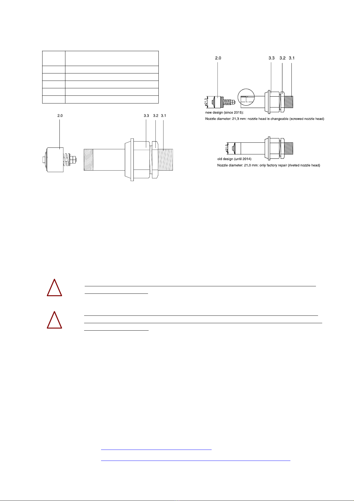
2.2 Replacement of the impulse nozzle with or without Pulsor:
The nozzle can be dismantled together with the Pulsor body or separately after unscrewing the Pulsor body (see
above).
When the impulse nozzle will be dismantled, there is always the danger that the product will flow
out of the silo. As far as possible, empty the silo before replacing a nozzle. Never dismantle the
impulse nozzle when product has just been filled or with a fluidised product. Switch off all fluidi-
sation devices, make the tank pressure-less and wait for the product to get vented of air. Always
wear safety glasses. With irritating, poisonous or corrosive products, wear protective clothing wi-
thout fail (eyewear, mask, etc.).
Before starting, shut off the compressed air supply and vent the feed pipe.
Disassembly:
a) Loosen and remove the solenoid valve plug.
b) Open the pipe union between Pulsor and valve. Detach the valve from the Pulsor and carefully hang valve
with hose aside.
c) Loosen the union nuts of the assembly union. Loosen the conical pipe union with light blows (rubber ham-
mer) and pull out the Pulsor with the impulse nozzle.
!
!
!

Re-Assembly:
d) Screw in the impulse nozzle into the Pulsor body without using a sealant and first tighten it by hand. Use
a screw wrench to tighten it by 1/8 - 1/4th of a revolution.
e) Insert the Pulsor with the impulse nozzle into the weld-on nipple. Align the Pulsor and the nozzle in such a
way that the valve can be installed easily. Firmly tighten the union nut of the assembly union.
f) Attach the valve, tighten the pipe union and fit the solenoid valve plug back on again.
3. Repair of the Pulsor:
Pulsor type 100, 150 und 300
1.1 Bottom
1.2 Plate
1.3 Sealing diaphragm
1.4 Valve disc
1.5 Plate spring
1.6 Seat ring (with Pulsor type 100 two-part)
1.7 ./.
1.8 Cover
1.9 Hexagon socket screw
1.10 Pipe double nipple, conical
1.11 Pipe union (screw-in part)
1.12 Monitoring sensor (optional)
1.13 Angle plug (optional)
1.14 Sealing (optional)
a) Remove the hexagon screws (1.9) and detach the Pulsor cover (1.8) from the Pulsor bottom (1.1). (Some-
times the cover adheres to the rubber diaphragm and can not be removed easily at once. For that reason
wait a few minutes after loosening the screws, until the cover can easily be removed (or carefully use a
screw driver or little chisel to open the housing.)
b) Inspect the Pulsor plate (1.2): The plate must be firmly glued into the bottom. When hit slightly with e.g. a
screw driver, a bright and clear sound must be heared. The sealing edge of the plate, on which the rubber
diaphragm sits, must not be damaged or have notches. The edge must protrude uniformly about 0,2 - 0,3
mm from the sealing surface of the bottom. If the Pulsor plate is damaged or loosened, the Pulsor should
be sent in for repair.
c) Inspect the valve disk and sealing diaphram (1.3+1.4) and replace it, if you discover ruptures or wear and
tear. The rubber diaphragm (1.3) must be firmly glued to the disk (especially at the inner perimeter), ex-
cept of a narrow zone along the edge of the disk (1.4). The central bore hole in the disk must not be clog-
ged. Its diameter is crucial for the working frequency of the Pulsor.
d) Inspect the plate spring (1.5) and the seat ring (1.6), and replace the parts, if worn.
e) If present, check the monitoring sensor (see chapter 6.3 of the operating manual). If the sensor is defect,
the Pulsor should be sent in for repair.
f) Reassemble the Pulsor, referring to the above sketch, paying attention to a good centering of the disk and
diphragm (1.3+1.4).

4. Repair of the Impulse Nozzle:
Impulse nozzle
type 20, 40 and 50
2.0 Nozzle head
3.1 Nozzle tube
3.2 Hexagon reducing socket
3.3 Union (insert part)
Impulse nozzle type 40 and type 50: Impulse nozzle type 20:
The nozzle head is screwed onto the nozzle tube since 2015: screwed nozzle head (Ø 21,3 mm)
until 2014: riveted nozzle head (Ø 21,0 mm)
After disassembly of the impulse nozzle, inspect nozzle tube and nozzle head. In case of significant corrosion or vi-
sible wear, the parts should be replaced. Particulary if the coil spring of the check valve has lost its tension and
the plate spring on the end face of the cap is loose, the nozzle head must be replaced. Check the function of the
non-return valve mechanism: it should just about be possible to turn the plate spring by hand on the end face of
the cap, and the nozzle bolt must be movable in its guide.
The head of the impulse nozzle is hardened and agglutinated to the nozzle tube (screwlock).
Do not screw off by force!
The nozzle head type 20 with a diameter of 21,0 mm (old design) can not be screwed off and
changed because it is riveted! Only the heads with a diameter of 21,3 mm (new design) can be
screwed off and changed.
a) For change of the nozzle heads carfully heat it with a propane/butane gas flame up to about 200°C, until
the screwlock disintegrates (white smoke). Clamp the nozzle head into a vice with pipe clamping jaws and
screw off the nozzle tube by turning the hexagon reducing socket with screw-wrench. (The hexagon redu-
cing socket is factory-made firmly agglutinated with the nozzle tube and should not be detachable).
b) Let nozzle tube cool down, clean the thread with a steel brush and screw on new nozzle head, using a sui-
table screwlock (Marston-Domsel, Loctite or similar).
5. Repair of the Solenoid Valves:
For technical data sheets and spare parts see:
Buschjost-Valves: http://www.buschjost.com/pdf/ 82960.pdf
ASCO-Valves: http://www.asconumatics.eu/images/site/upload/_en/pdf1/x003aagb.pdf
!
!
Table of contents
Popular Industrial Equipment manuals by other brands

Mid-West Instrument
Mid-West Instrument 109 Series Installation and operating instructions

KW
KW KLAB Series User and maintenance manual

HYDROSCAND
HYDROSCAND H16AP user manual

Carlisle
Carlisle Ransburg Aerobell 268 Service manual

Fröling
Fröling Lambdamat LM 800 installation instructions

schmersal
schmersal AZM201Z-I2-ST2-T-1P2PW instructions

Gema
Gema Vertical axis ZA16 Operating instructions and spare parts list

woodmizer
woodmizer Accuset 2 Safety, Operation, Maintenance & Parts Manual

Shurco
Shurco Donovan Spring Trap 2 owner's manual

woodmizer
woodmizer LT30HD Safety, Operation, Maintenance & Parts Manual

Oriental motor
Oriental motor AZ Series user guide

BIO-MICROBICS
BIO-MICROBICS BioBarrier 0.5 owner's manual