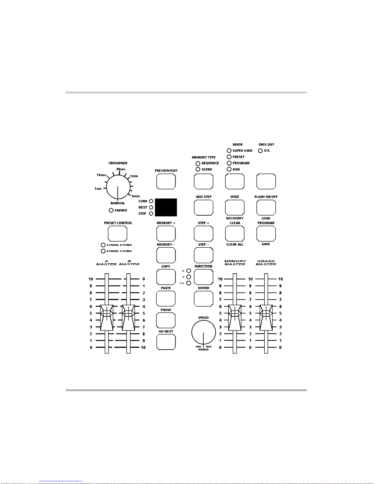
Master Controls and Displays
These controls set the general operating
conditions for the desk.
lMODE
The MODE button is used to select the
operational mode of the desk. The red
lights above the button show the current
operating mode (SUPER USER,
PRESET, PROGRAM, RUN).
lGRAND MASTER
The GRAND MASTER fader is used for
overall control of the maximum output
levels from all channels of the desk.
lBLACKOUT
The BLACKOUT button makes all the
desk outputs zero and operates in all
modes except SUPER USER. Pressing
the BLACKOUT button switches between
Blackout (all channels at zero) and normal
desk outputs.
The red light in the BLACKOUT button
indicates the current state (Flashing =
Blackout, Off = normal).
lDMX OUT OK
This light is illuminated when the desk is
transmitting digital data.
lWIDE
The WIDE button is used to select WIDE
operation. When in WIDE, the desk is a
single preset 24 (48) channel desk, rather
than a two preset 12 (24) channel desk.
With WIDE selected it is still possible to
crossfade between two scenes (see
Preset Mode for details). When WIDE is
selected the red light in the button is
illuminated.
lFLASH ON/OFF
The FLASH ON/OFF button is used to
enable/disable the CHANNEL FLASH
buttons. When the FLASH FUNCTION is
active, the red light in the button is
illuminated and the CHANNEL FLASH
buttons are enabled.
Turning on the Desk
1. Connect the DMX cable.
2. Connect the power supply to the desk
and switch on at the mains.
3. Ensure that DBO is not active (the red
light in the DBO button is off).
4. Set the GRAND MASTER fader to
full.
5. Set the A MASTER and B MASTER
faders to zero.
6. Set the CROSSFADE control to
manual.
Default State
When the desk is first switched on, or is
subsequently switched on and Recovery
Mode is off, the following default state is
entered:
MODE PRESET
BLACKOUT Normal Outputs
DISPLAY Not active
CURR light Off
NEXT light Off
STEP light Off
WIDE Not active
FLASH ON/OFF Active
SOUND Not active
All other lights Off
Page 6Alcora 73-700-00 Issue 2
Introduction