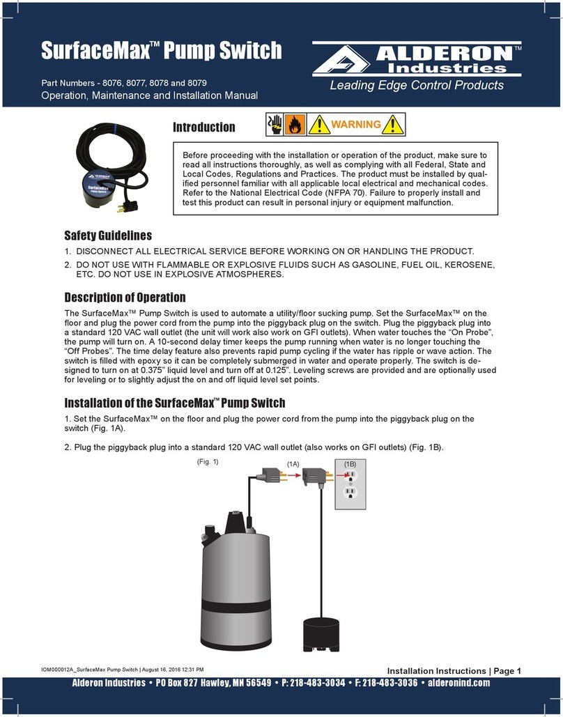
Alderon Industries ProbeX Series User manual

(120VAC Bare Lead Model - full product)
1. DISCONNECT ALL ELECTRICAL SERVICE BEFORE WORKING ON OR HANDLING THE PRODUCT.
2. DO NOT USE WITH FLAMMABLE OR EXPLOSIVE FLUIDS SUCH AS GASOLINE, FUEL OIL, KEROSENE,
ETC. DO NOT USE IN EXPLOSIVE ATMOSPHERES.
3. PROBEX™ PUMP SWITCH MUST ONLY BE USED WITH PUMPS CONTAINING INTEGRAL THERMAL
MOTOR OVERLOAD PROTECTION.
Safety Guidelines
Before proceeding with the installation or operation of the product, make sure
to read all instructions thoroughly, as well as complying with all Federal, State
and Local Codes, Regulations and Practices. The product must be installed by
qualied personnel familiar with all applicable local electrical and mechanical
codes. Refer to the National Electrical Code (NFPA 70). Failure to properly install
and test this product can result in personal injury or equipment malfunction.
Introduction
PUMP
DO NOT Install in
the Water Reservoir
MUST Install the ProbeX™ Housing/Enclosure
OUTSIDE of the Reservoir
Allowable to install ONLY THE PROBES in a pond or water feature
where humans or animals can contact the water
120VAC Model
(pump switch housing/enclosure only)
ProbeX™ Probes
(Reference, Stop/Red, and Start/Green)
Line Voltage
Low Voltage
Submersible
Pump
Allowable to install ProbeX™ in
a tank with a Submersible Pump
WARNING! Do not allow the ProbeX™ pump switch housing/enclosure and power cable to be submerged in ponds or other environments that can be a shock
hazard to humans or animals. The probes however, are low voltage (12VDC), and can be in the water if the ProbeX™ housing/enclosure is mounted out of the
water. For applications where a submersible pump is used, the ProbeX™ is completely waterproof and can be submerged in the same tank.
Alderon Industries • PO Box 827 Hawley, MN 56549 • P: 218-483-3034 • F: 218-483-3036 • alderonind.com
Installation Instructions | Page 1
QSG00118_Rev02_IOM000022B ProbeX Pump Switch | September 23, 2020 6:43 AM
Operation, Maintenance and Installation Manual
ProbeX™ Series Vertical Pump Switch
ProbeX™Pump Switch

(STOP)
(START)
(REFERENCE)
(Fig. 4 - Pump Down)
Pumping
Range
(Fig. 1 - Pipe Mount) (Fig. 2 - Wall Mount)
(2A) (2B)
Mounting Bracket Holes
bracket only
bolts/screws not included
(Fig. 3)
Loosen / Tigthen to Adjust
Stop and Start Probe Sensor Levels
(START)
(STOP)
(REFERENCE)
(Fig. 5 - Pump Up)
Pumping
Range
1. Determine mounting method of the ProbeX™ for your application (WARNING! Review Safety Guidelines). For
mounting on a pipe or pump discharge pipe, see gure 1 and for wall mounting, see gure 2. For piggyback plug
models, make sure an outlet or receptacle is within the distance of the ProbeX™ power cable prior to mounting.
Installation of the ProbeX™
2. Determine the pumping range for your application. The reference probe is submerged in the water with the
distance between the stop and start probes creating the pumping range.
3. For “Pump Down” applications, see gure 4. The “Reference” probe is the lowest mounted probe, followed by
the “Stop” probe (red label) in the middle, and the “Start” probe (green label) on top. Loosen cable grips (Fig. 3) and
pull the cables through - raising or lowering to the desired levels and securely fasten by tightening the cable grips.
4. For “Pump Up” applications, see gure 5. The “Reference” probe is the lowest mounted probe, followed by the
“Start” probe in the middle, and the “Stop” probe on top. Loosen cable grips (Fig. 3) and pull the cables through -
raising or lowering to the desired levels and securely fasten by tightening the cable grips.
The ProbeX™ Pump Switch is a vertical pump switch operated by three suspension probes. Typically used for liquid
level control in storm water collection, pond fill, water tanks, sump pumps, pilot/control circuits to energize magnetic
motor contactors, and any similar application where the water levels need to be controlled. Available in 120/230VAC
bare lead (no plug), 120VAC piggyback plug, and 230VAC piggyback plug, 15 Amp models with standard or custom
power and suspension probe cable lengths. The power is transformed to a safe low voltage of 12VDC at the probes.
The ProbeX™ pump switch can be mounted to a pipe, wall, or flat surface with the include mounting bracket and
stainless steel pipe clamp (bolts/screws not included if mounting to a wall or flat surface). Three suspension probes
are included for reference, stop, and start levels in the mounting area. The stop (red) and start (green) probes are
pre-wired into cable grips on the mounting bracket which allows for easy adjustments of the off and on levels per
application. A RubberLox™adjustable strap is included to secure excess probe cable below the pump switch housing.
Description of Operation
Alderon Industries • PO Box 827 Hawley, MN 56549 • P: 218-483-3034 • F: 218-483-3036 • alderonind.com
Page 2 | Installation Instructions
ProbeX™- Installation Instructions

(Fig. 7)
(7A) (7B)
(Fig. 8) (Fig. 9)
POWER SOURCE
G N L1 WIRE USING
JUNCTION BOX
120 VAC
GT2 T1
G
BLACK
WHITE
RED
PUMP
G L2 L1
230 VAC
GT2 T1
G
BLACK
WHITE/RED
RED
POWER SOURCE
WIRE USING
JUNCTION BOX
PUMP
ProbeX™
Power Cable ProbeX™
Power Cable
(Fig. 6)
RubberLox™
Power Cable
(120VAC example shown)
5. Excess cable should be neatly bundled and secured with the
included RubberLox™ adjustable strap and remaining between
the bracket (Fig. 6). CAUTION! Do not secure probe cables next
to the power cable as magnetic interference while the pump is
running may interfere with the liquid detection electronics and
may cause erratic operation such as continuous pump running.
6. For piggyback plug models, plug the pump power cable into the female piggyback plug on the ProbeX™ pump
switch (Fig. 7A), and then plug the male end of the piggyback plug into the receptacle (voltage depends on model;
Fig. 7B). After the pump and piggyback plugs are connected to a receptacle, see page 4 for testing.
7. For hardwire models connecting to a pump, 120VAC models see gure 8 and 230VAC models see gure 9.
Installation of the ProbeX™ Continued
Alderon Industries • PO Box 827 Hawley, MN 56549 • P: 218-483-3034 • F: 218-483-3036 • alderonind.com
Installation Instructions | Page 3
ProbeX™- Installation Instructions

(Fig. 10) (Fi g. 11)
120 VAC Model
ProbeX™ ON LY 230 VAC Model
ProbeX™ ON LY
L1
120 VAC
Power
L1
N
Disconnect
L1
L1 N L1 (Switched)
120 VAC
15 Amp
Detection
Circuit
M1
L1
L2
T1
T2
A1 A2
120V Coil
M1
Example Wiring
to 120V Pilot Circuit
Black
White
Red
L1
L1
L2
Disconnect
L1
L1 L2 L1 (Switched)
230 VAC
15 Amp
Detection
Circuit
M1
L1
L2
T1
T2
A1 A2
230V Coil
M1
Example Wiring
to 230V Pilot Circuit
Black
White/Red
Red
230 VAC
Power
1. After all the steps of the installation process have been completed, supply power to the pump switch and peform
testing.
2. “Pump Down” Models - Raise the water level in the tank or monitoring area until the “stop” probe is submerged
in water, the pump should not start. Continue raising the water level until the “start” probe is also submerged, the
pump should start, and remain on until the water level recedes below the bottom of the “stop” probe. Repeat this
process a couple of times to ensure the system is working properly.
3. “Pump Up” Models - Raise the water level in the tank or monitoring area until both the “stop” and “start” probes
are submerged in water to start the test. Lower the water level until it recedes below the bottom of the “stop” probe,
the pump should not start. Continue lowering the water level until the “start” probe is completely out of the water, the
pump should start and remain on until the water level touches the bottom of the “stop” probe. Repeat this process
a couple of times to ensure the system is working properly.
Testing the ProbeX™
The ProbeX™ uses an isolated patented circuit that detects water with no shock hazard at the probes.
1. Test system monthly to ensure pump switch and system integrity.
2. Keep both stainless steel probes clean and free of rust, mud, soap, or any type of non-conductive material by
inspecting and cleaning monthly.
Maintenance
8. For hardwire models connecting to a pilot/control circuit, refer to the wiring schematics below for 120VAC circuits
(Fig. 10) and 230VAC circuits (Fig. 11).
Installation of the ProbeX™ Continued
ProbeX™Pump Switch | Model Nomenclature and Custom Part Number Chart (custom lengths available)
ProbeX™ (P)
Pump Down (D)
or
Pump Up (U)
120VAC (1)
230VAC (2)
Without Plug (WOP)
Piggyback Plug (WP)
Pump Switch
Cable Length
(feet)
Suspension Probe
Cable Length
(feet)
P D 1WOP 15 S2
U2WOP 20 S5
1WP 25 S10
2WP 30 S20
50 S30
S50
Select one item from each column above and enter selections in the Model Number Boxes 1-5 below, this is your ProbeX™ Pump Switch Custom Part Number.
MODEL # BOX 1 MODEL # BOX 2 MODEL # BOX3 MODEL # BOX 4 MODEL # BOX 5
P
Example Part Number: PD1WP20S30 | ProbeX™ Pump Switch, Pump Down, 120VAC Piggyback Plug, 20' Pump Switch Cable, and 30' Probe Cable
Alderon Industries • PO Box 827 Hawley, MN 56549 • P: 218-483-3034 • F: 218-483-3036 • alderonind.com
Page 4 | Installation Instructions
ProbeX™- Installation Instructions
Other Alderon Industries Switch manuals
Popular Switch manuals by other brands

Pepperl+Fuchs
Pepperl+Fuchs Vibracon LVL-M2C instruction manual

RGBlink
RGBlink VENUS X1 PRO-E user manual

Ness
Ness Mezzo manual

Nortel
Nortel 2526T reference guide

Wöhner
Wöhner CAPUS SD1-3 instructions

Hearth and Home Technologies
Hearth and Home Technologies WSK-21-W Installation and operating instructions