Alderon Industries VertiMAC VM13 Series User manual

USERGUIDE
MODEL NUMBER:
VM13 Series
VertiMAC™
Pump Switch | 13 Amp

Contents
Introduction.................................................................................................................................................................3
Safety Guidelines...................................................................................................................................................3
Product Included....................................................................................................................................................4
Features.................................................................................................................................................................5
Installation ..................................................................................................................................................................6
Pump Differential....................................................................................................................................................6
Mounting Pump Switch ...................................................................................................................................7, 8, 9
Connecting Power................................................................................................................................................10
Testing..................................................................................................................................................................10
Additional Assembly and Product Information ................................................................................................11, 12
General Operation....................................................................................................................................................13
Sump Pump .........................................................................................................................................................13
Sump Pump with VertiMAC™ Sump Advisor™ System.......................................................................................14
Sump Pump with Battery Backup ........................................................................................................................15
Limited Space Dewatering ...................................................................................................................................16
Troubleshooting........................................................................................................................................................17
Specications ...........................................................................................................................................................18
Warranty Information................................................................................................................................................19
Company Information...............................................................................................................................................20
VertiMAC™ Pump Switch - USER GUIDE

Alderon Industries™ - Leading Edge Control Products | 3
VertiMAC™ Pump Switch - USER GUIDE
Introduction
The VertiMAC™ is a oat operated pump switch, typically used in sump pump applications or situations where a regular pump
switch cannot operate due to limited space. The product comes with a pipe clamp bracket and stainless steel pipe clamp for
mounting to a pipe. Available in 120VAC or 240VAC, bare lead (no plug) or piggyback plug, 13 Amp models.
Safety Guidelines
Before proceeding with the installation or operation of this product, read all instructions thoroughly, as well as complying with
all federal, state and local codes, regulations, and practices. This product must be installed by qualied personnel familiar with
all applicable local electrical and mechanical codes. Refer to the National Electrical Code (NFPA 70). Failure to properly install
and test this product can result in personal injury or equipment malfunction.
1. DISCONNECT POWER when installing or servicing the product. Failure to disconnect all power sources could result in
serious injury or death.
2. NEVER enter a ooded space without proper Personal Protective Equipment (PPE). Always wear dielectric rubber boots
and other applicable protective equipment when water is on the oor and you must service an energized pump, alarm
system, or product.
3. DO NOT enter the water if the water level is higher than that of the protection your PPE offers or if your PPE is not
watertight.
4. DO NOT use this product with or near ammable liquids.
5. DO NOT install this product in locations classied as hazardous or in explosive atmospheres as dened by any applicable
electrical safety code.
WARNING

4 | Alderon Industries™ - Leading Edge Control Products
VertiMAC™ Pump Switch - USER GUIDE
Product Included
(1) VertiMAC™ Pump Switch
The VertiMAC™ is a oat operated pump switch for sump pump
applications.
(2) Pipe Clamp Bracket
The pipe clamp bracket is pre-installed and used to mount the
pump switch to a pipe.
(3) Stainless Steel Pipe Clamp
The pipe clamp attaches to the pipe clamp bracket and secures
the pump switch to a pipe at the desired mounting location.
(4) Pump Switch Power Cable
The power cable is available in 120VAC or 240VAC, bare lead
(no plug) or piggyback plug, 13 Amp models.
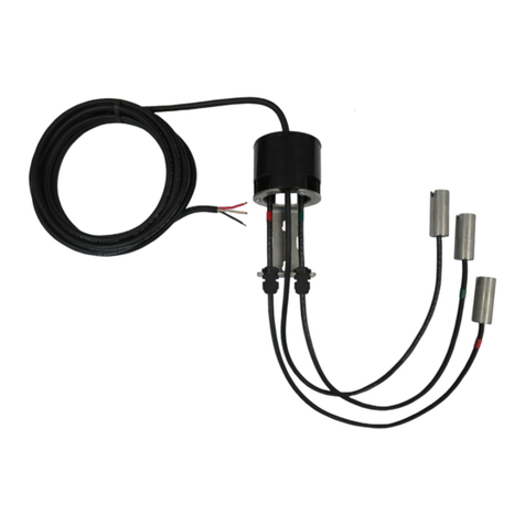
(5) Sump Advisor™ Sensor
The Sump Advisor™ sensor attaches on top of the VertiMAC™
pump switch and connects to the Sump Advisor™ alarm panel.
The sump sensor integrates the high level alarm and pump run
switches.
(6) Sump Advisor™ Alarm Panel
The Sump Advisor™ alarm panel provides local high level
alarm and pump run indication of the VertiMAC™ pump switch.
The alarm panel includes auxiliary dry contacts for high level
alarm and pump run status that can be connected to a building
automation system (BAS) or auto dialers.
ADDITIONAL OPTIONS:
The standard product will include: (1) VertiMAC™ Pump Switch, (1) Pipe Clamp Bracket, (1) Stainless Steel Pipe Clamp, and
(1) Pump Switch Power Cable.
56
2
3
1
4
(120VAC Piggyback Plug Model Shown)

Alderon Industries™ - Leading Edge Control Products | 5
VertiMAC™ Pump Switch - USER GUIDE
Features
Refer to the illustration below to reference the feature descriptions provided.
(1) VertiMAC™ Pump Switch Housing -
Magnetically
activated switching mechanism encapsulated in epoxy to
ensure a waterproof switch.
(2) Actuator Pin - Connects the actuator rod to the pump
switch housing to ensure proper activation of the switching
mechanism.
(3) Actuator Rod - Activates or deactivates the mechanism
inside the pump switch housing as the oat rises or lowers
on the rod.
(4) Float - Slides up and down the actuator rod to turn the
pump on and off.
(5) Rubber Grommet - Placed on the actuator rod at the
determined location for desired pump differential.
(6) Pipe Clamp Bracket - Pre-installed, attaches to the pump
switch housing and used to mount the VertiMAC™ pump
switch to a pipe.
(7) Stainless Steel Pipe Clamp - Attaches to the pipe clamp
bracket and secures the VertiMAC™ pump switch to a pipe at
the desired mounting location.
(8) Pump Switch Power Cable (not shown) - Available in
120VAC or 240VAC, bare lead (no plug) or piggyback plug, 13
Amp models.
(9) QR Code - Scan code which directs you to alderonind.com
where additional information can be found for the VertiMAC™
pump switch.
1
2
3
4
5
6
9
6
7

6 | Alderon Industries™ - Leading Edge Control Products
VertiMAC™ Pump Switch - USER GUIDE
Installation
DISCONNECT ALL POWER SOURCES WHEN INSTALLING OR SERVICING THIS PRODUCT. FAILURE TO
TURN OFF ALL POWER SOURCES COULD RESULT IN SERIOUS INJURY OR DEATH.
Pump Differential
STEP 1: DETERMINING PUMP DIFFERENTIAL
Determine the pump differential and move the rubber grommet on the actuator rod to achieve the desired range. After the pump
switch installation is complete, perform testing to achieve actual pumping differential.
Maximum Differential: Move the rubber grommet to the bottom of the actuator rod to create the largest pump differential, which
is six inches (6.0”).
Minimum Differential: Move the oat and rubber grommet to the top of the actuator rod to create the smallest pump differential,
which is one and a half inches (1.5”).
Note: Leave approximately one eighth inch (1/8”) of space between the rubber grommet and the bottom of the actuator rod to
achieve the maximum differential. Placing the rubber grommet at the bottom of the rod could cause the grommet and oat to
separate from the actuator rod.
(Pump Activated)
(Pump Deactivated)
Maximum (6.0”)
Pump Differential
(Pump Activated)
(Pump Deactivated)
Minimum (1.5”)
Pump Differential

Alderon Industries™ - Leading Edge Control Products | 7
VertiMAC™ Pump Switch - USER GUIDE
Mounting Pump Switch
STEP 1: RELEASE PIPE CLAMP
The pipe clamp comes secured into the fastener (1A) and must
be released (1B) using either a slotted screwdriver or 5/16” nut
driver on the fastener nut.
1A
1B
STEP 2: INSTALL PIPE CLAMP
Slide the pipe clamp through the loop on the pre-installed pipe
clamp bracket of the VertiMAC™ pump switch.
Note: Make sure the pipe clamp is positioned as shown in the
diagram when installing so excess portion of the clamp exits the
fastener away from the pump switch.

8 | Alderon Industries™ - Leading Edge Control Products
VertiMAC™ Pump Switch - USER GUIDE
Mounting Pump Switch (continued)
STEP 3: MOUNTING TO PIPE
Attach the pipe clamp to pipe at the approximate mounting level
and tighten using the fastener nut. Make sure to keep all cables
and wires away from the oat while mounting.
Note: Do not completely secure pipe clamp and VertiMAC™
pump switch to the pipe until the off level has been determined.
See step 4 nal mounting location on page 9.
CAUTION: The VertiMAC™ pump switch MUST be mounted in
the vertical position. Mounting the pump switch at an angle will
result in the switch not functioning properly. Perform a quick test
by lifting the oat up and down to ensure the switch is working.

Alderon Industries™ - Leading Edge Control Products | 9
VertiMAC™ Pump Switch - USER GUIDE
STEP 4: FINAL MOUNTING LOCATION
After the off level of the VertiMAC™ pump switch has been determined, check to make sure level is above the intake to the
pump to prevent dry cycling. Refer to the instructions that came with the pump for complete operation information. Once the
pump switch is in the nal mounting location, securely fasten the pipe clamp and VertiMAC™ pump switch to maintain an
accurate pumping range.
Mounting Pump Switch (continued)
PUMP
VertiMAC™
Pump Switch
VertiMAC™
Off Level
Pump
Intake

10 | Alderon Industries™ - Leading Edge Control Products
VertiMAC™ Pump Switch - USER GUIDE
Connecting Power
PIGGYBACK PLUG MODELS
1) Plug the male end of the piggyback plug on the VertiMAC™
pump switch power cable into a standard wall outlet or power
receptacle that matches the voltage of the pump switch (A).
2) Plug the male end of the pump power cable into the female
end of the piggyback plug on the VertiMAC™ pump switch
power cable (B).
B
A
VertiMAC™ Pump Switch
Piggyback Plug
Power Cable
Pump
Power Cable
Testing
Activation Level
Deactivation Level
Pumping
Range
Make sure the installation process is completed and there is
power to the product.
STEP 1: TEST PUMP OFF
When the actuator rod is in the down position (deactivated), the
pump should be off.
STEP 2: TEST PUMP ON
When the actuator rod is in the up position (activated), the pump
should be on.
STEP 3: PUMPING RANGE
After testing is complete, the pumping range can be adjusted
by moving the rubber grommet up or down the actuator rod to
achieve the desired pump differential.
WARNING: If making any adjustments to the VertiMAC™ pump switch after
testing has been completed, make sure to disconnect all power sources before
servicing the product.
BARE LEAD MODELS
1) Connect bare lead wires from the VertiMAC™ pump switch
power cable to terminal inputs in a junction box as shown in
the diagram.
WARNING: In 240VAC installations, one side of the line going to the load is
always HOT. This condition exists if the switch is on or off. Install double pole
disconnect on all 240VAC circuits.
Make sure the installation process is completed and there are
no cables or wires to interfere with the operation of the oat.
POWER SOURCE
G L2/N L1
WIRE USING
JUNCTION BOX
120/240 VAC
G
BLACK
WHITE
LOAD
G L2/N L1

Alderon Industries™ - Leading Edge Control Products | 11
VertiMAC™ Pump Switch - USER GUIDE
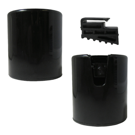
This VertiMAC™ pump switch model comes pre-assembled with the actuator rod, oat, and pipe clamp bracket installed. The
pumping differential is set at the maximum range (6.0”). If adjustments or servicing is required, use this section for additional
instructions on the VertiMAC™ pump switch.
Additional Assembly and Product Information
MOUNTING PIPE CLAMP BRACKET
Place the pipe clamp bracket on the bottom of the VertiMAC™
pump switch housing and line up the holes. Use a #2 phillips
head screwdriver to securely fasten the bracket to the housing
with provided screws.
INSERTING ACTUATOR ROD
Slide the actuator rod arm upward into the front of the VertiMAC™
pump switch housing, positioned so the notch on the actuator arm
matches the side of the housing with the hole. If the actuator rod
arm is inserted in the correct position, the pump switch housing
should make a clicking sound as the rod slides up and down.
ACTUATOR PIN PLACEMENT
Once the actuator rod arm has been placed into the VertiMAC™
pump switch housing in the up position, insert the actuator pin
into the small hole on the left side of the housing until it snaps
in place.

12 | Alderon Industries™ - Leading Edge Control Products
VertiMAC™ Pump Switch - USER GUIDE
Additional Assembly and Product Information (continued)
RUBBER GROMMET AND FLOAT PLACEMENT
Slide the oat onto the actuator rod, positioned so the text “This
Side Up” on the oat is facing up and then slide the rubber
grommet onto the actuator rod to secure the oat on the rod.
The pump differential can be adjusted by sliding the rubber
grommet up and down the actuator rod. See step 1 determining
pump differential on page 6.
PUMP SWITCH: PUMP OFF and PUMP ON
When the actuator rod is in the down position (deactivated), the
mechanism inside the VertiMAC™ pump switch housing turns
the pump off (A).
When the actuator rod is in the up position (activated), the
mechanism inside the VertiMAC™ pump switch housing turns
the pump on (B).
Adjustable
Rubber Grommet
(off level)
THIS SIDE UP
THIS SIDE UP
BA

Alderon Industries™ - Leading Edge Control Products | 13
VertiMAC™ Pump Switch - USER GUIDE
General Operation
The VertiMAC™ is a oat operated pump switch, typically used in sump pump applications or situations where a regular pump switch
cannot operate due to limited space. The VertiMAC™ pump switch is mounted in a vertical position to a pipe and is activated by
the oat upon a rising water level. As the water level rises, the oat pushes the actuator rod upward which activates the mechanism
inside the pump switch housing and turns the pump on. When the water level recedes, the oat lowers the actuator rod downward
deactivating the mechanism inside the pump switch housing and turns the pump off. To adjust the pump differential, slide the rubber
grommet up or down the actuator rod for the desired pumping range. The applications are not limited to what is listed in this user
guide. Follow all individual instructions for sensors and accessories used with the VertiMAC™ pump switch.
The following applications can be found in this user guide: Sump Pump, Sump Pump with VertiMAC™ Sump Advisor™ System,
Sump Pump with Battery Backup, and Limited Space Dewatering.
Sump Pump
The diagram below is a typical setup for a sump pump application. The VertiMAC™ pump switch is mounted to the discharge
pipe and powered by a standard wall outlet using the piggyback plug power cable. The pump power cable is then plugged into
the female end of the VertiMAC™ piggyback plug. The oat is used to operate the pump switch, turning the pump on and off
based on the pump differential for the desired pumping range.
5:05
PM 71%
REGENERATION
MENU ENTER
House to YardVertiMAC™
Pump Switch

14 | Alderon Industries™ - Leading Edge Control Products
VertiMAC™ Pump Switch - USER GUIDE
Sump Pump with VertiMAC™ Sump Advisor™ System (pump switch, sensor, and alarm panel)
The diagram below is a typical setup for a sump pump with indoor alarm application. The VertiMAC™ pump switch is mounted to the
discharge pipe and powered by a standard wall outlet using the piggyback plug power cable. The pump power cable is then plugged
into the female end of the VertiMAC™ piggyback plug. The oat is used to operate the pump switch, turning the pump on and off
based on the pump differential for the desired pumping range. The Sump Advisor™ sensor is an accessory option which is mounted
to the top of the VertiMAC™ pump switch and connected to the Sump Advisor™ alarm panel for local high level alarm and pump run
indication.
When the water level rises, the oat pushes the actuator rod upward which activates the mechanism inside the pump switch housing
and turns the pump on. The Sump Advisor™ sensor will send a signal to the Sump Advisor™ alarm panel, activating the green pump
run LED indicator and the pump run auxiliary dry contacts (which can monitor pump run counts and run time by BAS systems). If
the water level rises activating the high level alarm oat on the sensor, the red high sump LED indicator, buzzer, and alarm auxiliary
dry contacts on the alarm panel will activate. Pressing the alarm silence pushbutton will silence the buzzer. When the water level
recedes, the oat lowers the actuator rod downward which deactivates the mechanism inside the pump switch housing and turns the
pump off. When the alarm condition is cleared, the system will automatically reset itself for the next alarm cycle.
5:05 PM 71%
REGENERATION
MENU ENTER
House to Yard
VertiMAC™
Pump Switch
Sump Advisor™
Alarm Panel
Sump Advisor™
Sensor

Alderon Industries™ - Leading Edge Control Products | 15
VertiMAC™ Pump Switch - USER GUIDE
Sump Pump with Battery Backup
5:05 PM 71%
REGENERATION
MENU ENTER
House to Yard
VertiMAC™
Pump Switch
(primary)
VertiMAC™ Pump Switch with
Sump Advisor™ Sensor
(backup)
The diagram below is a typical setup for a sump basin where a VertiMAC™pump switch and VertiMAC™ pump switch with
Sump Advisor™ sensor control a 120VAC or 240VAC operated pump (primary) and a 12VDC operated pump (battery backup).
The primary pump is controlled by the primary VertiMAC™ pump switch where the piggyback plug is plugged into a standard
wall outlet and the pump power cable is then plugged into the female end of the VertiMAC™ piggyback plug. The VertiMAC™
pump switch with installed Sump Advisor™ sensor will be mounted slightly higher than the primary pump switch as a backup.
The cables for the backup pump switch and sensor are connected to the control panel for the battery backup system.
When the water level rises and activates the primary VertiMAC™ pump switch, the primary pump will turn on until the water level
recedes and deactivates the pump switch turning the primary pump off to complete the pump cycle. If the water level continues
to rise and activates the backup VertiMAC™ pump switch with Sump Advisor™ sensor, the backup pump will turn on until the
water level recedes and deactivates the pump switch turning the backup pump off. If the water level rises activating the high
level alarm oat on the Sump Advisor™ sensor, it will activate the high level alarm on the control panel. When the water level
recedes the high level alarm oat on the sensor will deactivate to clear the alarm condition on the panel. The VertiMAC™ pump
switch and Sump Advisor™ sensor allows for a compact trouble-free installation for sump pump systems with battery backup.

16 | Alderon Industries™ - Leading Edge Control Products
VertiMAC™ Pump Switch - USER GUIDE
Discharge
VertiMAC™
Pump Switch
6.0” Pipe
Limited Space Dewatering
The diagram below is a typical setup for a dewatering application where a pump switch cannot operate due to limited space.
The VertiMAC™ pump switch is mounted to the discharge pipe inside a six inch (6.0”) pipe placed in the ground. With the pump
and discharge pipe inside the small size of the pipe, a typical pump switch would not have enough space to pivot and activate
the pump. The VertiMAC™ pump switch and pump power cables are wired to terminal inputs in a junction box. The oat is used
to operate the pump switch, turning the pump on and off based on the pump differential for the desired pumping range.

Alderon Industries™ - Leading Edge Control Products | 17
VertiMAC™ Pump Switch - USER GUIDE
Troubleshooting
PROBLEM PROBABLE CAUSE SOLUTION
Float stuck in the up position after water
has pumped out of the tank Float or actuator rod has an obstruction
preventing its normal operation Remove obstruction and make sure the
oat and actuator rod operate properly
VertiMAC™pump switch is mounted at
an angle preventing normal operation of
the oat or actuator rod
Remount the VertiMAC™ pump switch
so the oat and actuator rod operate in a
vertical manner
Float in the down position while the
pump continues to run Internal switch has failed The VertiMAC™ pump switch is at the
end of its life cycle, replace immediately
Float in the up position but the pump
does not turn on Power is not applied to either the pump
or VertiMAC™ pump switch Make sure the VertiMAC™ piggyback
plug power cable is properly connected
and outlet or receptacle has power
Bare lead models, make sure there is
power to the pump and VertiMAC™
pump switch
The pump or VertiMAC™ pump switch
have failed Replace the pump or VertiMAC™ pump
switch
Pump differential is not at the desired
range for specic application Rubber grommet on the actuator rod
has not been properly set Adjust rubber grommet position on the
actuator rod either up or down to change
the pump differential

18 | Alderon Industries™ - Leading Edge Control Products
VertiMAC™ Pump Switch - USER GUIDE
Specications
Primary Voltage:
Electrical:
Cable Type:
Connection Types:
Pumping Range:
Operating Temperature:
Certications:
120VAC or 240VAC, 60 Hz (voltage depends on part number)
13 Amps, 120VAC 0.5HP or 240VAC 1.5HP
SJT, 16 gauge
Bare Lead (no plug; 120/240VAC)
Piggyback Plug (120VAC or 240VAC; voltage depends on part number)
1.5” - 6.0” (inches)
0 - 140° F
CSA (US and Canada)
Note: The VertiMAC™ pump switch must be used with pumps that provide integral thermal overload protection.

Alderon Industries™ - Leading Edge Control Products | 19
VertiMAC™ Pump Switch - USER GUIDE
Warranty Information
LIMITED WARRANTY: Subject to the conditions of this Three-Year Limited Warranty, Alderon Industries, LLC (“Alderon”) war-
rants to the original user or consumer of an Alderon product (the “Product”) that, for a period of three (3) years from the date of
manufacture, the Product will be free from defects in materials and workmanship under normal use and service, and provided
the Product is installed, operated and maintained in accordance with instructions supplied by Alderon.
WARRANTY EXCLUSIONS: Notwithstanding anything to the contrary, this Limited Warranty does not cover:
1. Alderon custom control units. Please see the One-Year Limited Warranty – Custom Controls.
2. Damage, defects or malfunctions resulting from (a) failure to properly install, operate or maintain the Product in accordance
with printed instructions provided and with applicable local codes, ordinances and good trade practices; (b) normal wear and
tear; (c) abuse, accident or negligence; (d) de-installation and movement of the Product from its original installation location;
(e) repair and/or modication of the Product without prior authorization from Alderon; (f) use of the Product for purposes other
than for what it was designed and manufactured; or (g) conditions beyond the control of Alderon, including lightning and freight
damages (hidden or visible). Contact parcel or the freight company for claims on freight damage in transit.
3 Cost of eld labor or other charges incurred by you in removing and/or re-afxing the Product or any part or component
thereof.
4. Transportation costs.
CLAIM PROCEDURE: To make a claim regarding breach of warranty, (a) the claim must be received by Alderon before the ex-
piration of the warranty period; and (b) the defective Product, or part thereof, must be returned to a designated Alderon location,
FREIGHT PREPAID, together with proof of purchase. A return goods authorization must be received prior to the return of the
defective Product or part. Please contact the sales representative in your area to determine the designated Alderon location for
return and to obtain the return goods authorization. If you do not have a sales representative in your area, please call 218-483-
3034 to submit your claim, or mail notice of your claim to:
Warranty Claims
Alderon Industries, LLC
P.O. Box 827
Hawley, MN 56549
EXCLUSIVE REMEDY: In the event of a warranty claim that Alderon determines to be covered by this Limited Warranty, Al-
deron will, at its option, repair or replace the Product.
The above limited warranty and this exclusive remedy are the sole express warranty and remedy given by Alderon on the Prod-
uct. No warranties or representations at any time made by any representative from Alderon shall vary or expand the provisions
hereof. TO THE EXTENT PERMITTED BY LAW, ALL EXPRESS AND IMPLIED WARRANTIES (INCLUDING IMPLIED WAR-
RANTIES OF MERCHANTABILITY, FITNESS FOR A PARTICULAR PURPOSE AND NON-INFRINGEMENT) OTHER THAN
THE EXPRESS LIMITED WARRANTY SET FORTH ABOVE ARE EXPRESSLY DISCLAIMED. UPON THE EXPIRATION OF
THE ABOVE STATED LIMITED WARRANTY PERIOD, ANY AND ALL APPLICABLE IMPLIED WARRANTIES, INCLUDING,
WITHOUT LIMITATION, WARRANTIES OF MERCHANTABILITY, FITNESS FOR A PARTICULAR PURPOSE AND NON-IN-
FRINGEMENT, ARE DISCLAIMED. SOME STATES DO NOT ALLOW LIMITATION ON HOW LONG AN IMPLIED WARRAN-
TY LASTS, SO THE ABOVE LIMITATION MAY NOT APPLY TO YOU.
THIS WARRANTY GIVES YOU SPECIFIC LEGAL RIGHTS AND YOU MAY ALSO HAVE OTHER RIGHTS, WHICH VARY
FROM STATE TO STATE.
LIABILITY LIMITATION: In no event will Alderon’s liability to you or any other person or entity exceed the price paid to Alderon
for the defective Product. IN NO EVENT SHALL ALDERON BE LIABLE TO YOU OR ANY OTHER PERSON OR ENTITY
FOR INCIDENTAL, CONSEQUENTIAL, INDIRECT OR SPECIAL DAMAGES OF ANY DESCRIPTION, WHETHER ARISING
OUT OF WARRANTY (INCLUDING ANY IMPLIED WARRANTIES) OR ANY OTHER CONTRACT, STRICT LIABILITY, NEG-
LIGENCE OR OTHER TORT, OR OTHERWISE, INCLUDING ARISING FROM INSPECTION OR REMEDY DELAYS. SOME
STATES DO NOT ALLOW THE EXCLUSION OR LIMITATION OF INCIDENTAL OR CONSEQUENTIAL DAMAGES, SO THE
ABOVE LIMITATION AND EXCLUSION MAY NOT APPLY TO YOU.
Three-Year Limited Warranty - Standard Products
62800933.2

Company Location: 151 16th Street South, Hawley, MN 56549
Mailing Address: PO Box 827, Hawley, MN 56549
Main Ofce Phone: 218.483.3034
Website: alderonind.com
General Inquiry Email: info@alderonind.com
Submit New Orders: order[email protected]
UG00012_Rev01_VertiMAC Pump Switch 13A | July 5, 2018 10:15 AM
A
L
D
E
R
O
N
I
N
D
U
S
T
R
I
E
S
™
L
E
A
D
I
N
G
E
D
G
E
C
O
N
T
R
O
L
P
R
O
D
U
C
T
S
Table of contents
Other Alderon Industries Switch manuals