Aler AL200 User manual

HD Vehicle MDVR
Declaration: The Alersec company has the right of final interpretation to this Guide.
Information contained herein is subject to change without prior notice due to continuous
improvement of the product and technology.
Quick Installation Guide

Table of Contents
1. Introduction.......................................................................................- 1 -
2. Preparations....................................................................................- 1 -
3.Power Connection...............................................................................- 2 -
4.Video Input Mode Setting..................................................................- 3 -
4.1 Camera Connection Mode........................................................- 3 -
4.2 Software Setting.......................................................................- 5 -
5.Online Setting .....................................................................................- 6 -
6.Introduction to Remote Control........................................................- 9 -
7.Usage Precautions.............................................................................- 10 -

- 1 -
1. Introduction
The MDVR adopts ARM DSP fast dual-core processor running on the Linux embedded OS,
and also integrates the most advanced H.264 video encoding/decoding in IT industry, 3G/4G
network, GPS and WiFi, as well ascircuit protection, HDD shock absorption, HDD heating,
operation at wide voltage rangefeatures. It is characterized by strong functionality, good
scalability, good stability and high performance cost and extensively applied in public buses,
logistics vehicles, school buses, police cars, financial convoy cars and fuel tankers.
2. Preparations
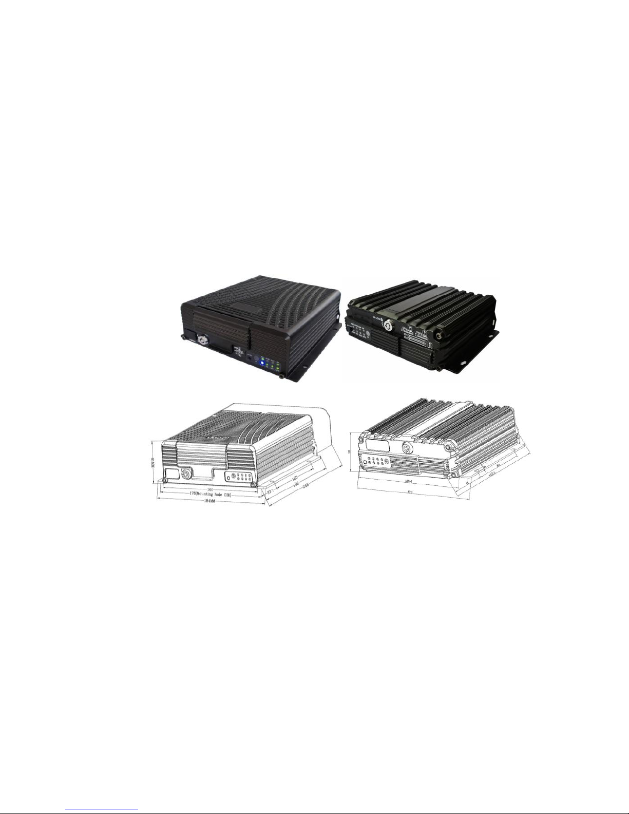
Figure 1 Physical Figure and Dimension Diagram
To turn the key anticlockwise to unlock the electronic lock and open the front cover, and
install HDD/SD card and SIM card in turns;
To install GPS, WiFi and 3G/4G antenna depending on the product configuration;
To select the position where the camera will be installed and arrange proper wiringto
connect it to the Mobile DVR;
To select a display and connect it to the video outputportof the MDVR.

- 2 -
1. To turn the electronic lock clockwise to lock it after HDD/SD card and SIM card
are installed; otherwise, the device will not be powered on;
2. To ensure prolonged and stable operation, it is advised to have the device
horizontally installed and take waterproof measures;
3.It is recommended to install 3G/4G, GPS and WiFi antennas in a place where it
will not be blocked signal or be able to receive strong signal;
4.This product has 8 channels of alarm inputs, 1 channels of alarm output, one
RS485, and two RS232 extended externalports which allow connection
toappropriate devices according to requirements of vehicles;
3. Power Connection
To connect the yellow cable of the power cord to ACC, the control circuit switch of the
vehicle, and the red and black ones are respectively connected to positive and negative electrode
of the vehicle power supply and then to vehicle MDVR. When testing the wiring condition,
twisting the red cable and yellow cable together and connect to the positive electrode, while the
black one is connected to the negative electrode.
Figure 2 Power Wiring Diagram
It is suggested that the MDVR power cable to be directly connected to the positive and negative
terminals of the vehicle battery cell (or the vehicle battery cell with fuse box). DO NOT connect
the MDVR power cable to any metal conductor subjects of the vehicle, which may influence
normal operation of the MDVR due to negative pulse; The power cable used for positive and
negative terminals shall have diameter of φ1.5mm or above.

- 3 -
4. Video Input Mode Setting
This product is a hybrid HD vehicle MDVR allowing connection with various types of
cameras. Table 1 shows portdefinitions of analog cameras. The IP camera port is standard port. A
user shall select camera type according to hardware connection port and configure proper
settingsin the software.
Connection
Diagram
Pin
Number
Interface
Definition
Connection
Diagram
Pin
Number
Interface
Definition
Pin
Number
Interface
Definition
1
12V OUT
1
12V OUT
5
A-IN-2
2
GND
2
GND
6
V-IN-2
3
A-IN
3
A-IN-1
4
V-IN
4
V-IN-1
Table 1 Air Interface Definition
4.1 Camera Connection Mode
Connection
Mode
Connection Diagram
Model AL200-HYBRID
Connection of
analog camera
3 1
4 2
4channels of D1/960H/720PAHD video
inputs
2 channels of 720p AHD(1&2 CH)
+2*960H (3&4 CH)analog hybrid video
inputs
Connection ofIP
camera
4 channels of 720P/1080P IPC video inputs
Hybridconnection
of analog and IP
camera
4 channels of IPC+4*720PAHD/960H/D1
HD hybrid video inputs
Table 2 AL200-HYBRID Connection Mode
Connection Mode
Connection Diagram
Model AL300 -HYBRID
Connection of
analog camera
8 channels of CIF/ D1/960H analog video
inputs

- 4 -
Connection ofIP
camera
4 channels of 720P/1080P IPC video inputs
Hybridconnection
of analog and IP
camera
4 channels of 720P IPC+8*960H/D1/CIF
HD hybrid video inputs
Table AL300-HYBRID Connection Mode
Connection
Mode
Connection Diagram
Model AL2000-HD
Connection of
analog camera
3 1
4 2
4 channels of D1/960H/720PAHD video
inputs
2 channels of 720p AHD(1&2 CH)
+2*960H (3&4 CH)analog hybrid video
inputs
Hybrid
connection of
analog and IP
camera
1channels of 720P/1080P
IPC+4*720PAHD/960H/D1 HD video
inputs,connection to an external switch is
also acceptable.
Table 4 AL2000-HD Connection Mode
Connection Mode
Connection Diagram
Model AL3000-HD
Connection of
analog camera
8 channels of CIF/ D1/960H analog video
inputs
Hybrid connection
of analog and IP
camera
1channels of 720P/1080P
IPC+8*960H/D1/CIF HD hybrid video
inputs,connection to an external switch is
also acceptable.
Table 5 AL3000HD Connection Mode
Connection
Mode
Connection Diagram
Model AH100-HD
Connection of
analog camera
3 1
4 2
4 channels of D1/960H/720PAHD video
inputs
2 channels of 720p AHD(1&2 CH)
+2*960H(3&4 CH)analog hybrid video
inputs
Hybrid
connection of
analog and IP
camera
Max. 4 channels of 960H video inputs +
1 channel of 1080P IPC HD video input,
connection to an external switch is also
acceptable.
Table 6 AH100-HD Connection Model

- 5 -
Notice ,when connect 4channel 720P AHD cameras or 4*960H+1*1080P IPC camera ,need to
use High speed SD card(4K card,speed more than 80M/S)
4.2 Software Setting
After connecting the camera according to above connection
methods, from the Setup menu →Channel Mode interface, select
the desired connection mode and save it and the system will
automatically restart. Then, from the Setup menu →Record Setup
→Main Stream and IPC setting, where you can set video resolution,
frame rate, picture quality, audio recording and IP address for each
channel (Following figures show JH4-HYBRID setting interface.
Settings for the 8 channelsMDVR are similar).
After Channel Mode is selected, the MDVR will automatically restart and enter the related setting
interface. IPC setting is not available if only an analog camera is connected.

- 6 -
Figure 3 AL3000 HD Setting Interface
When adding a camera, select the related channel and you can manually input the IP address
and port number of the IP camera, or click "Search" to select the desired IP camera in the search
result. The user name and password are set for the IP camera. For a IP camera with security
feature, the setting shall be the same as that for the IP camera itself; or this setting can be ignored.
Use remote control to move to the letter you want, press "Enter" to confirm your selection and
press "Return" to return and complete your input.
5. Online Setting
When uploading your device to the server via 3G/4G network, you shall set the device
number, vehicle number, server IP and the wireless network before you can remotely manage it
via remote CMS/IVMS client.
1. Press the "LOGIN" key on the remote control, and input the initial password 888888. From the
Setup menu →General →Vehicle Info, complete the device number and related vehicle number.
Other information can be filled in as necessary. Only when the mileage statistic is enabled can
you count the mileage in the server client;

- 7 -
Figure 4 Vehicle Information Setting Interface
2.。
2.Return to the Basic Setup interface and enter the Network interface to set the server IP address
and control port, by default, 6608; When an external IP camera is connected, you shall set the IP
address of the RJ45 port, with its network segment same as that of IP address of the IP camera. In
addition, set the IP address of the gateway server as the first IP address in this network segment
(e.g. 192.168.000.001, being the first IP in network segment 0).
Figure 5 Network Setting Interface
Usercan choose to either establish its own server or use a server provided by the MDVR
manufacturer. Please contact the MDVR manufacturer for technical support who will provide
and assign the device number, server IP and user name & password of the client to the user. The
user would simply fill provided information into the vehicle MDVR and can manage the related
vehicle via the serverclient.
3. Return to Setup menu → Peripheral Setup → Wireless Setup, and select the network type
corresponding to your SIM card (the following figure shows the difference between 3G and 4G
Please ensure your device number is unique which
will be used by the remote server to monitor and
manage your vehicle.
Please ensure your vehicle number is correct
which will be superimposed on the video.

- 8 -
software). Fill in the access point name (APN), center number, user name and password provided
by your operator; select the network type. For Chinese operators, select AUTO. For international
subscribers, fill in the information provided by your local mobile operator.
Figure 6 Wireless Setup Interface
4. On the monitoring screen, press the "INFO" key on the remote control to check the connection
status and ensure that connected devices such as 3G/4G, GPS and WiFi work normally, and that
the vehicle device is successfully connected to the server center.
Figure 7 System Information Query Interface
车After MDVR settings are completed, you can go to the server to add the related vehicle

- 9 -
and authorize it to the corresponding administrator account. In this case, the CMS/IVMS client
can remotely manage and monitor your device (In case that your device is managed by the
manufacturer, please consult it with the manufacturer; for those establishing their own server,
please contact our technical support for help).
6 Introduction to Remote Control
You can use your remote control to set the MDVR system. The following section takes an
example of text input to simply explain the use of your remote control. For example, when you
are to enter company name, vehicle number, driver name orroute number or other information
during parameter setting, the remote control shall be used. For instance, to enter the vehicle
number " BY52CCP ",
You shall do as follows:
To input the letter B/Y/C/P by movingthe cursor to ↑S, pressing "Enter" to switch input
method to English Capital mode, moving your cursor to letter "B/Y/C/P"and pressing
"Enter" to input this letter.
Then, input numbers. Press the ↑S again to switch to Chinese input mode where you
cannot input numbers. In this case, you shall move your cursor to "中" key, and press the
"ENTER" key to change it to "EN", and then input number "52.".
On completion, press "Return" key to return and save it. Please follow the same procedures
for other texts. If any error occurs during input, please press "Cancel" to delete it.
Figure 8 Text Input Interface

- 10 -
7Usage Precautions
1. Installation Environment
To extend thedevice life, please try to install the device in a place where vibration is weak;
To ensure normal heat dissipation, do not install the device in a poorly-ventilated area, and
also keep about 15 cm away from other objects on the same level;
The device shall be horizontally installed and protected against water, humidity and
lightning; in addition, keep the vehicle still during installation to prevent damage to the
device due to falling off;
To ensure safe operation, keep the device, camera, cables and other accessories out of
reach of passengers and driver.
2. Avoid Electric Shock and Fire
8V-36V DC power supply is used for this device. Please note the positive and negative
terminals during connection to prevent short circuit;
Please power the device off before connecting any peripheral ;
Do not touch the power supply and the device with wet hands;
Do not spray liquid on the device to prevent internal short circuit or fire;
Do not place any other device directly on top of the camera;
Do not disassemble the housing without authorization to avoid damage or electric shock;

- 11 -
3. Transport and Handling
To prevent incidental damage to the device during transport. Handle the device with due
care. The original packaging materials and carton are preferred;
Power the device off before handling or part replacement to prevent any damage;

Thank your for choosing our product. We will provide you with best and considerate
services! Firstly, you can contact our customer service for one-to-one technical support during use
of our product; secondly, the product quality is guaranteed within the warranty period and the
freight incurred from returning the product to the company will be half and half; finally, the
company provides remote software upgrade service free of charge.
Outside China: the mainframe of the MDVR is guaranteed for 15 months; 12 months for the
camera.
China: both mainframe of the MDVR and camera are guaranteed for 12 months. (separate them if
it is to print)
Contact:
Phone number:
Address:
Purchase
time/vendor:
Warranty period:
Problem description
Warranty
period:
Problem description
Warranty Card
Warranty Policy

Dear users, if any non-artificial quality defect is found on reception, please contact the
responsible salesman of your vendor, and after our confirmation, return the device to our
after-sales department for maintenance, together with this warranty card.
This manual suits for next models
4
Table of contents
Other Aler DVR manuals
Popular DVR manuals by other brands

i3 International
i3 International VEO 16 Quick operation manual

Q-See
Q-See QSDR74RTS user manual

HIK VISION
HIK VISION DS 7204HQHI K1/B quick start guide

Storage Options
Storage Options 8 Channel DVR instruction manual

HIK VISION
HIK VISION DS-6701HFI Quick operation guide

HIK VISION
HIK VISION DS-8104AHGHLI-E4 quick start guide