ALEXANDER ENGEL 212 Supplement

Item No. 1599
212
Assembly & Operation
Manual
Parts List
Since 1952
Please read the following building instructions and safety warnings carefully
BEFORE commencing with assembly of kit and installation of technical equipment.
Please also refer to the safety guidelines on page 38.
WARNING!
During the charging period all batteries must be removed from the hull. NEVER
charge the batteries within the hull as most regular lead batteries gas while being
charged. Insufficient air circulation during the charging period may lead to a
serious EXPLOSION!
Please adhere to your country’s safety guidelines during construction and operati-
on of this item.
We are not liable for any personal injury or damage of any kind resulting with the
assembly and/or use of our products as we are neither able to delegate nor verify
the assembly and/or use of these items.
We reserve the right to alter technical specifications.
Copyright ©2011 ALEXANDER ENGEL KG Bi1599 v1-11 All rights reserved.
www.modelsubmarines.com
ALEXANDER ENGEL KG
Quality Model Kits & Accessories since 1952
P.O.Box 1133 D-75434 Knittlingen • Germany • Phone: int.+49 (0)7043-93520 Fax: int.+49 (0)7043-31548 • Email: [email protected]
Submarine Class

212
Item No. 1599
Bi1599 v1-11
2
Table of Contents
Introduction . . . . . . . . . . . . . . . . . . . . . . . . . . . . . . . . . . . . . . . . . . . . . . . . . . . . . . . . . . . . . . . . . . . . . . .3
Part A1. Battery Compartment . . . . . . . . . . . . . . . . . . . . . . . . . . . . . . . . . . . . . . . . .5
2. Installation of Cables and Tubes . . . . . . . . . . . . . . . . . . . . . . . . . . . . . . . .6
3. Mounting and Connection of CTS to Piston Tank . . . . . . . . . . . . . . . . . . .7
4. Centre Section . . . . . . . . . . . . . . . . . . . . . . . . . . . . . . . . . . . . . . . . . . . . . .9
5. Servo Block . . . . . . . . . . . . . . . . . . . . . . . . . . . . . . . . . . . . . . . . . . . . . . . .11
6. Main Drive Battery and Arrangement of Wire Leads . . . . . . . . . . . . . . . .13
7. Receiver Battery and Arrangement of Wire Leads . . . . . . . . . . . . . . . . . .14
8. Installation of Speed Controller . . . . . . . . . . . . . . . . . . . . . . . . . . . . . . . .15
9. Power Socket . . . . . . . . . . . . . . . . . . . . . . . . . . . . . . . . . . . . . . . . . . . . . .16
10. Central Plug . . . . . . . . . . . . . . . . . . . . . . . . . . . . . . . . . . . . . . . . . . . . . . .16
11. Charge Lead . . . . . . . . . . . . . . . . . . . . . . . . . . . . . . . . . . . . . . . . . . . . . . .17
12. Joining of Servo Block, Centre Section and Piston Tank . . . . . . . . . . . . .17
13. Installation of Steering Gear . . . . . . . . . . . . . . . . . . . . . . . . . . . . . . . . . . .18
14. Main Drive . . . . . . . . . . . . . . . . . . . . . . . . . . . . . . . . . . . . . . . . . . . . . . . .19
15. Main Bulk Head . . . . . . . . . . . . . . . . . . . . . . . . . . . . . . . . . . . . . . . . . . . .21
16. Push Rods and Linkages . . . . . . . . . . . . . . . . . . . . . . . . . . . . . . . . . . . . .23
17. Bayonet Lock Ring . . . . . . . . . . . . . . . . . . . . . . . . . . . . . . . . . . . . . . . . . .26
18. Receiver, Speed Controller, Servos and Pitch Conroller . . . . . . . . . . . . .28
19. Initial Launch of CTS with Piston Tank . . . . . . . . . . . . . . . . . . . . . . . . . . .29
20. Joining Tech Rack and Hull . . . . . . . . . . . . . . . . . . . . . . . . . . . . . . . . . . .30
Part B 21. Control Planes at Stern, Dive Planes at Sail . . . . . . . . . . . . . . . . . . . . . .30
22. Hull Ridge, Bilge and Side Keels . . . . . . . . . . . . . . . . . . . . . . . . . . . . . . .31
23. Main Ballast . . . . . . . . . . . . . . . . . . . . . . . . . . . . . . . . . . . . . . . . . . . . . . .33
24. Revision Opening and Cover . . . . . . . . . . . . . . . . . . . . . . . . . . . . . . . . . .34
25. Propeller and Spinner . . . . . . . . . . . . . . . . . . . . . . . . . . . . . . . . . . . . . . . .34
26. Conning Tower Mechanism (optional) . . . . . . . . . . . . . . . . . . . . . . . . . . .35
Part C 27. Leak Test . . . . . . . . . . . . . . . . . . . . . . . . . . . . . . . . . . . . . . . . . . . . . . . . .36
28. Trimming . . . . . . . . . . . . . . . . . . . . . . . . . . . . . . . . . . . . . . . . . . . . . . . . . .36
Part D 29. Paintwork . . . . . . . . . . . . . . . . . . . . . . . . . . . . . . . . . . . . . . . . . . . . . . . . .37
30. First Voyage . . . . . . . . . . . . . . . . . . . . . . . . . . . . . . . . . . . . . . . . . . . . . . .37
31. Maintenance . . . . . . . . . . . . . . . . . . . . . . . . . . . . . . . . . . . . . . . . . . . . . . .37
32. Safety Guidelines . . . . . . . . . . . . . . . . . . . . . . . . . . . . . . . . . . . . . . . . . . .38
Part Listing . . . . . . . . . . . . . . . . . . . . . . . . . . . . . . . . . . . . . . . . . . . . . . . . . . . . . . . . . . . . . . . . . . . . . . .39
This symbol indicates that after the service life of this electrical
device has ended it must be disposed separately from domestic
refuse at your communal waste collection.

The 212 class has become increasingly popular since its release, this is true for the original boat as well as the miniaturised
model.
This new ENGEL submarine offers besides radial parting with bayonet lock ring and Tech Rack© very compact dimensions
and easy handling. Hull, sail and all other attaching parts are highly detailed. The Tech Rack© slides into the front part of the
hull offering easy access to most of the boat's internal components.
Building is straight forward and quite simple as all parts are prefabricated . Hull, bayonet lock rings, control planes and hull
attachments are cast in resin and require little to no adjustment. The Tech Rack© is constructed of sturdy CNC-machined,
interlocking parts, reinforced with ready-made brass bars. Piston Tank included features AutoStop, meaning that the piston
drive will automatically stop at an instant as soon as the tank is completely filled or emptied. Piston Tank and electronic switch
unit CTS are both fully built forming a compact unit without extensive and frail wiring.
Hull unit, bayonet lock ring, control planes and main bulk head are all cast in resin. Except for the control planes, all other
resin cast parts should be glued with a slower setting two-component adhesive such as 1-Hour Epoxy (item no. 9507).
Consistency of adhesive can be adjusted by adding a filling agent such as Micro Balloons (item no. 9567). This combinati-
on will set after about 1 hour. Full adhesive strength will be reached after 12-24 hours.
Less demanded joints can be glued with Cyano (also called CA or Superglue). Abottle of high, medium and low viscosity CA
is available as set (item no. 960246). All surfaces to be bonded must be thoroughly cleaned with white spirit or thinner.
Dive Set with Piston Tank and CompactTankSwitch CTS
The 212 is equipped with a Piston Tank type EA500-123 in 12 Volt featuring AutoStop. This ensures that the piston drive will
automatically stop at an instant as soon as the cylinder is fully filled or empty.
CompactTankSwitch CTS and Piston Tank form a compact unit. The CTS can be operated via a control stick or a 3-position
switch (on-off-on) on the transmitter.
The CTS is fitted with high amp PROFETs offering excessive power reserves. The CTS can easily cope with a stalled Piston
Tank motor for several minutes without any damage.
This compact unit offers all necessary fail-safe features such as
• Low Battery Monitor
• Loss of Transmitter Signal
• Optional Automatic Resurfacing if model dives below approx. 1.8 m
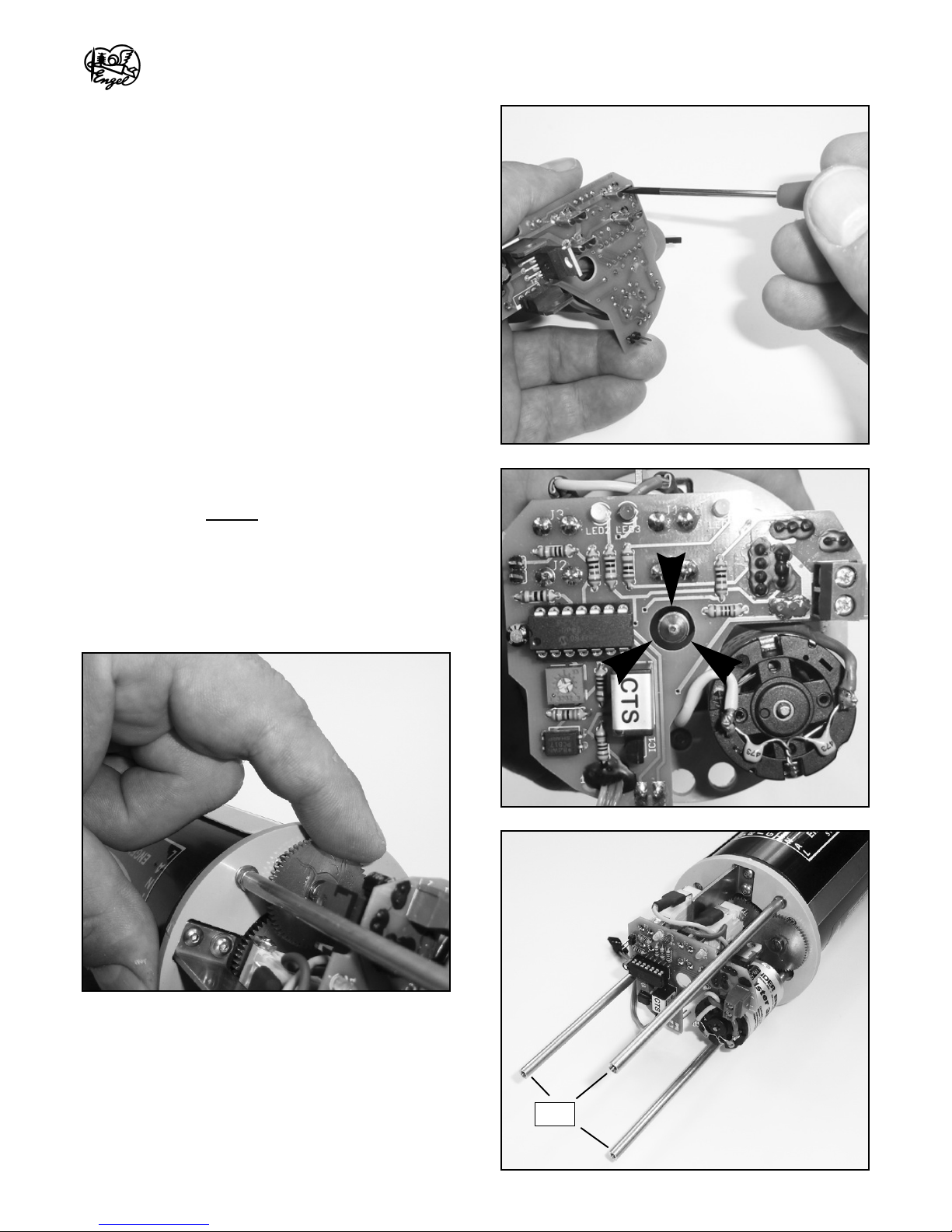
If voltage drops below a preset value (factory setting approx. 9V for 12V operation) the Piston Tank is automatically switched
to empty. This so-called threshold voltage can be adjusted via the potentiometer on board of the CTS. However, a regulated
power supply is recommended to achieve an exact setting. Turning the screw of the potentiometer (slowly!) in clockwise
direction will increase threshold voltage, turned anti-clockwise will decrease this value.
With battery voltage already lower than threshold value when system is powered up will lead to deactivation of this safety
device. This mode is indicated by the red LED flashing. However, the CTS will be in service despite low voltage. This mode
will prove helpful for verifying correct direction of flow of the Piston Tank.
If the receiver signal is lost - due to increased depth or other circumstances - the CTS will also switch to "blow" (empty) the
Tank.
With the Pressure Switch connected, maximum depth is limited to approx. 1.8 meters (6 ft). If the model dives below this
level, the CTS will automatically switch to the "resurface" and empty the Piston Tank. The model will then resurface unless
the switch is set back to its upper position. Otherwise, with the switch left at "submerge" the model will emerge to a depth
above 1.8 meters after which the Tank will start filling again (and so on). Furthermore, the Pressure Switch acts as a second
safety device. Should the over pressure which builds-up within the hull while submerging (by filling the Tank) be lost due to
a leakage, the "submerge mode" will be terminated. In this case, the red LED blinks steadily, and the system does not allow
the model to dive again until this has been corrected.
Functional Principle of Conning Tower Mechanism (optional, item no. 1599-1)
This mechanism drives periscopes, radar, snorkel and antennas in- and outwards of the conning tower.
When the model submerges, i. e. Piston Tank is filling, the pressure within the model increases. At about 80% filling volume
the pressure within the boat activates piston movement in a cylinder built into the mechanism. This movement moves a slide
into the conning tower on which the devices are mounted.
Copyright ©2011 ALEXANDER ENGEL KG
212
Item No. 1599
3

As soon as the submarine re-emerges to the water surface the pressure within the model decreases (as the Piston Tank
empties), whereby periscopes, radar, snorkel and antennas retract.
The mechanism also serves as safety indicator. Should the model suffer a leakage during its dive, the over-pressure within
the boat will decrease forcing the conning tower mechanism to extract. Aclear indication to bring the model back safe to
shore and check for a possible leakage. This mechanism is fully-built, ready-to-run unit and requires no further assembly.
The manual is divided in three main sections A, B and C. Part Adescribes assembly of the Tech Rack, thus, the internal setup
of the model. Part B is devoted to hull and its adjoining parts, part C to ensuring leak tightness and basic trim. Part D gives
a short outline on painting and finish of the model. This conclusive part also gives some hints on the boat's maiden voyage
and further servicing.
Please also refer to the part listing at the end of this text. This listing is sorted by part group. The separately held packing list
is sorted by pack numbers.
Further items required/recommended to complete this model:
• Conning Tower Mechanism for retraction of periscope, radar and antennas, item no. 1599-1
• Wire and Connector Set, item no. 1599-99
• Battery Pack High-Power NiMH 12V/3500mAh + Receiver Battery NiMH 4,8V/3000mAh, item no. 5556
• Boat Stand made of Polycarbonate, aluminum and stainless steel, item no. 1599-Z
• Pitch Controller DLx for X-rudders, item no. 1573
• Electronic speed control Rookie 20, item no. RO8400
• Servo FS 500 MG, item no. RO8431 (only this servo will fit, requires 2)
• 1-Hour Epoxy 224 g, item no. 9507
• Micro Balloons, 250ml, item no. 9567
• Rapid CA superglue set, 3x 20g, item no. 960246
Adhesives and Lubricants:
• 1-Hour Epoxy, item no. 9507
• Micro Balloons, item no. 9567
• Rapid CA Superglue Set, item no. 960246
• CA Accelerator, item no. 96200
• Q-Lube, high-performance adhesive lubricant, item no. 9705
• TITAN Grease, item no. 9707
212
Item No. 1599
Bi1599 v1-11
4

Copyright ©2011 ALEXANDER ENGEL KG
212
Item No. 1599
5
1. Battery Compartment
1.1 Assemble compartment from two side parts T3, one bottom
part T4 and bow bulkhead T1. Cut-out in bottom part lies against
pre-fitted bulk head of Piston Tank (for clearance of screw in end
cap of tank).
NOTE: Assemble parts DRY- DO NOT GLUE. Verify correct
arrangement and orientation of bow bulk head.
1.2 Glue with medium viscosity CA (item no. 96040). Apply glue
on front face of side parts as well as on bottom part. Remove
excess glue IMMEDIATELYwith pointed blade.
1.3 Glue carrier T2 (for Pressure Switch) to bow bulk head.
1.4 Glue completed section against pre-fitted bulk head of
Piston Tank.
NOTE: Apply CA very sparingly to avoid gluing of bulk head to
end cap of Piston Tank. Otherwise parting of section and disas-
sembly of Piston Tank will become difficult or even impossible.
Part A
The Tech Rack is built from CNC-milled plastic parts, brass bars and the Piston Tank. The Rack is divided in four sections.
First, the battery compartment, which takes the two main batteries as well as the receiver pack. The carrier for the Pressure
Switch is fitted in front the compartment's bulk head at bow. Second, the Piston Tank with switch unit CTS, with the neces-
sary bulk heads factory-fitted to both ends of the tank. Third, the so-called Centre Section accepting receiver and power
socket. Fourth, the servo block, consisting of two bulk heads and a mounting plate for the speed controller.
Battery compartment and Piston Tank will form a single section after assembly. This section can be parted again by unscr-
ewing three bolts in the tank's front bulk head. Piston Tank and Centre Section should be joined at an advanced building
stage; that way merging of hull section and Tech Rack will prove less difficult.
Before you start with the assembly we highly recommend to build a simple stand for your model. Aprofessionally made boat
stand for the 212 is also available as an option (item-no. 1599-Z). Cover the stand with cling film or cloth.
Another helpful option is the power socket with main plug located in the Centre Section. All electric components can be swit-
ched off simply by pulling a single plug. In addition, the power socket also serves as charging socket for both main and recei-
ver battery. Wire and Connector Set, item no. 1599-99, includes all wires and connectors for this kit (complimentary to
Battery Pack item no. 5556).
T3
T4
T3 T1
T2
PS
T1 T2
+

1.5 Push Pressure Switch in carrier T2 and check for good fit.
1.6 Accessibility of screws in Piston Tank bulk head is given by
three corresponding holes in bow bulk head (see picture).
212
Item No. 1599
Bi1599 v1-11
6
2. Installation of Cables and Tubes
2.1 Insert three brass tubes, outer dia. 7 mm, which are two
parts S6 with length 249 mm and one part S7 with length 332
mm into the bores of both Piston Tank bulk heads as shown.
2. 2 Insert brass tube S8, outer dia. 3 mm, length 332 mm, into
the corresponding bores of both Piston Tank bulk heads as well
as bow bulk head. This tube connects to Pressure Switch via
silicone tubing X2; cut to length of approx. 48 mm. Push both
ends of tubing about 6 mm onto Pressure Switch and brass tube
S8.
2.3 Cut PVC tubing X1, outer dia. 9 mm, to 275 mm length.
Push onto nozzle in back plate of Piston Tank. Feed tubing
through upper bore of bow bulk head down to brass tube S7.
Push end of tubing about 8 mm onto brass tube.
S7
S8
S6
X2
X1

Copyright ©2011 ALEXANDER ENGEL KG
212
Item No. 1599
7
3. Mounting and Connection of CTS to Piston Tank
3.1 Before mounting CTS to Piston Tank, make up cables
connecting motor poles to tags of micro switches from wires,
yellow and violet (each. about 120 mm long) as well as blade
receptacles and heat shrink tube supplied with CTS. Skin each
wire end and tin coat with soldering iron. Crimp one receptacle
onto each wire. Cut heat shrink tube supplied in half (to about
20 mm), push over receptacles and shrink with heat gun
(>90°C). Solder other wire end directly onto connection tag of
motor.
3.2 Connection is made as illustrated.
Yellow to micro switch S2, tag 1 and "+" pole of motor.
Violet to micro switch S1, tag 1 and counter-pole of motor.
3.3 Install wires accurately around spindle and motor.
3.4 Coat contact tags of micro switches with contact spray in
order to prevent oxidation.

212
Item No. 1599
Bi1599 v1-11
8
3.5 Before sliding the CTS onto the micro switches, slightly
press contact tags 2 and 4 of each Piston Tank together so that
the tags lie parallel to one another. This will facilitate fitting of the
unit. CAREFULLYwiden the blade receptacles (pre-soldered to
the CTS' back side) with a small screwdriver.
3.6 Slide receptacles of CTS CAREFULLYonto the micro swit-
ches. This will require some pressure but must be done with
GREATCARE to avoid damaging the circuit board.
3.7 Align CTS in accordance to Piston Tank. The spindle must
run, more or less, in the CENTRE of the centre bore in the CTS.
Turn the spindle a bit outwards by spinning of middle gear
wheel. Proper adjustment can easily be accomplished by
carefully pressing the circuit board in the appropriate direction.
When Piston Tank and Centre Section are merged at a later
stage, guiding tube S5 will be inserted into this bore of the CTS.
3.8 Screw three brass bars S3, length 124 mm, to the corre-
sponding threaded bolts protruding the Piston Tank's bulk head.
Bars are tightened by hand only!
S3

Copyright ©2011 ALEXANDER ENGEL KG
212
Item No. 1599
9
4. Centre Section
4.1 Remove parts from milled sheet and sand down fillets.
4.2 Assemble Centre Section, commencing with back part T11
onto bottom plate T8. Ensure right angle by placing one side
part against back part and bottom. Glue T11 onto T8 with CA.
4.3 Add side parts T9 and T12 with CA.
4.4 Place top cover T10 onto assembly, align accordingly and
copy bores onto back and side parts. Drill with 1.5 mm bit, about
5 mm deep. Countersink all four bores in top cover T10 (diame-
ter 5 mm at 90 degree angle). Use reamer or, if not at hand, a
matching drill bit. Top cover is fastened with four countersunk
self-tapping screws 2.2x6.5 mm - DO NOT GLUE!
4.5 Prior to final assembly purpose-made power socket must be
installed into opening of the Centre Section's right-hand side
part (seen from aft to bow). This building sequence is described
in chapter 9.
T12
T8
T10
T11
T9
drill bit
1.5
Bore for fastening
Pitch Controller
DLx

212
Item No. 1599
Bi1599 v1-11
10

Copyright ©2011 ALEXANDER ENGEL KG
212
Item No. 1599
11
5. Servo Block
5.1 Firstly, sand down remaining fillets from outer diameter of
servo bulk heads T5 and T7. Trim T5 to fit snugly through inner
bayonet lock ring R4. Bulk head should just fit into the ring; not
too lose.
5.2 Fit two brass bars S4, length 30 mm, with screws Y2 (allen
head) to bulk head T5.
5.3 Glue mounting plate T6 for speed controller against back
side of T5.
5.4 Prior to installation of servos, remove servo discs.
NOTE: Bulk heads accept exclusively servo type FS 500 MG
BB (item no. RO8431).
5.5 Push servo retaining plates into slots of bulk head T5. Servo
lead and shaft face towards bow. Draw servo leads through the
cut-outs in bulk head T7 and push T7 onto the servo in position.
5.6 Glue Central Section against bulk head T7.
NOTE: Top cover is not fastened, yet, but only placed onto
Central Section to ensure right angle.
5.7 If Dual Pitch Control DLx is used, mount DLx now on portsi-
de of Central Section (screw and nut are supplied with DLx).
Pass both servo leads to the DLx and plug-in accordingly. The
JST connector (red) should also be plugged onto the two pin
row for automatic pitch reverse on the DLx. Pass the two wire
leads through both servo bulk heads beneath the mounting
plate for the electronic speed controller (ESC). Do not cut wire,
yet.
S4
T5
Y2
R4
T5

212
Item No. 1599
Bi1599 v1-11
12

Copyright ©2011 ALEXANDER ENGEL KG
212
Item No. 1599
13
6. Main Drive Battery and Arrangement of Wire Leads
6.1 The main drive battery consists of two individual packs with
5 cells each (size Sub-C) and a capacity of 3500 mAh. Each
pack adds up to 6 Volt (5x 1.2 Volt). In order to acquire the
necessary on-board voltage of 12 Volt the two packs must be
switch in row.
6.2 Parting of the fully wired Tech Rack sections requires inser-
tion of several connectors. Cable and connector set no. 1599-
99 includes two pair of plugs and sockets 3.5 mm, one pair with
and one without housing. For the receiver power line there are
also two pair of plugs, and again one pair with and one without
housing.
6.3 The two main drive battery packs stand on portside (left,
seen from aft to bow) and in centre position. The receiver bat-
tey pack is placed starboard. Protruding wire leads always face
towards the aft.
6.4 Cut positive wire lead (red) of one main battery pack (5554)
to a length of 50 mm. Cut negative wire lead (black) of second
main battery pack to a length of 30 mm. Skin both leads by
about 5-7 mm.
6.5 Push a piece of heat shrink tube 4.8 x 20 mm onto the lon-
ger (red) wire lead. Join formerly skinned wire ends and solder
together. Leave to cool down.
6.6 Place heat shrink tube over the soldered joint and shrink
with heat gun (>90°C). This serial connection of battery packs
results in a nominal voltage of 12 Volt.
6.7 Cut the remaining wire leads to a length of 150 and respec-
tively 170 mm. The centrally positioned pack is left with the 20
mm longer wire lead.
NOTE: Cut one wire at a time - risk of SHORTCIRCUIT!
6.8 Strip insulation of both wires by about 3 mm and tin-plate
with soldering iron. Melt some soldering tin in both plugs and
sockets type CT-3.5. Push red housing onto both wire leads.
Ribbing of the housing lies towards battery packs. Solder plug
to positive lead (red), socket contact to negative (black) lead.
6.9 Solder leads, leave to cool and press connectors into hou-
sings. Housings fit snugly between water tube of Piston Tank
and bottom plate of battery compartment.
6.10 The remaining lengths of wires are used as extension
leads from this connector towards the power socket at Centre
Section. Determine cable length required, measured from CT-
3.5 connector through cable guiding tube S6, ending just below
switch unit CTS (approx. 350 mm). Cut accordingly.
Gold Connector CT-3.5
socket
plug

212
Item No. 1599
Bi1599 v1-11
14
7. Receiver Battery and Arrangement of Wire Leads
7.1 Place receiver battery pack (5528), consisting of 4 cells type
Sub-C (4.8 Volt), on portside of battery compartment.
7.2 Determine required wire length from battery pack to under-
side of battery compartment (approx. 100 mm) and cut accor-
dingly. Remaining wires with connector will be needed at a later
stage.
NOTE: Cut one wire at a time - risk of SHORTCIRCUIT!
7.3 Strip insulation of wires by about 2-3 mm, tin-plate and sol-
der to connector CT-2 with housing. Solder positive (red) lead to
plug, negative (black) to socket.
7.4 Extend receiver battery lead with silicone wire 0.5 sqmm
(cross section), approx. wire length 300 mm. Wire leads for
receiver power are passed through second guiding tube S6,
together with cable connecting CTS to Pressure Switch (PS).
Red JST connector connects to two-pole pin row on lower back
side of CTS.
7.5 As for the main power leads, wire ends towards receiver bat-
tery are fitted with CT-2 connectors with housing. 2 mm connec-
tors below CTS are fitted without housing and insulated with
heat shrink tube 3.2 mm. Fit connectors to remaining cable
lengths accordingly and insulate in the same manner.
7.6 Feed connection leads for PS through bow bulk head and
solder to contacts 1 and 3 of PS. Polarity is irrelevant here.
Wires can be fastened with a piece of spiral cable wrap (also
included in 1599-99) alongside Piston Tank tubing.
6.11 Strip insulation of wires by about 3 mm and tin-plate.
Solder contacts with housing in accordance to CT-3.5 connec-
tor formerly fitted to main battery packs. Solder 3.5 mm socket
and plug (supplied without housing) to wire ends below CTS.
These connectors are insulated with heat shrink tube 4 x 8 mm.
6.12 Remaining length of wires are fitted with socket and plug
3.5 mm, again without housing. Ensure correct pairing of
connectors. These two wire leads will be soldered to the power
socket within the Centre Section at a later stage.
Gold Connector CT-2
socket
plug

Copyright ©2011 ALEXANDER ENGEL KG
212
Item No. 1599
15
8. Installation of Speed Controller (Rookie 20)
8.1 Cut TAM style connector from power lead (black/red) of
electronic speed controller (ESC) and feed through triangular
openings in both servo bulk heads T5 and T7, just below bottom
plate of Centre Section.
8.2 Solder plug and socket 3 mm (without housing) to these two
leads, leave to cool and insulate with heat shrink tube 4.8 mm.
8.3 Shorten connection lead of ESC to motor (blue/white) by
approx. 95 mm (measurement for Rookie 25, item no. RO8400).
Solder this length of wire to main drive motor, blue to "+" pole,
white to counterpole.
8.4 Solder sockets 3 mm (without housing) to both wire ends of
ESC. If Dual Pitch Controller DLx is used, solder ESC wires
together with leads for automatic pitch reverse of the DLx.
Solder wire with black vein together with WHITE lead.
8.5 Solder plugs 3 mm to both ends of motor leads.
8.6 Insulate all plugs and sockets with transparent heat shrink
tube 4.8 mm.
8.7 As the R/C system aboard is powered by a receiver battery
the BEC (Battery Eliminating Circuit) system provided by the
ESC remains unused. The BEC itself must therefore be elimi-
nated. To interrupt this circuit, pull the red wire lead out of the
plug connecting to the receiver. Insulate bare connector with
tape as shown.
8.8 Should direction of rotation be inverse, meaning that in for-
ward mode the propeller spins anti-clockwise (seen from aft to
bow), polarity of motor can easily be reversed by inverting the
wire leads (blue/white) between ESC and motor.
8.9 ESC can be fixed with double-sided adhesive tape onto its
mounting plate. Only use high-quality tape as adhesive strength
of cheap tape will soon deteriorate, especially in a moist envi-
ronment.

212
Item No. 1599
Bi1599 v1-11
16
9. Power Socket
Applies to optional cable and connector set, item no. 1599-99.
9.1 This socket is located within the Central Section, fitted in a
frame to an opening in the side of that section. The socket feeds
power from the main drive and receiver battery to the model's
electric and electronic components. Furthermore, the socket
allows easy charging of all battery packs at a single central
point.
9.2 Feed wires coming from main drive and receiver battery
through slot in bottom plate T8 as well as cut-out in the side
part. Cut wires to length. Strip insulation of wires by about 4 mm
and tin-plate with soldering iron.
9.3 Push MPX style socket (green, with pin contacts) into frame
(black) and retain with a small drop of CA (medium viscosity,
item no. 96040). Place the shorter strain relief circuit board (11
mm) onto the contact pins protruding the back side of the
socket. Apply tin solder. Solder wire ends to circuit board accor-
ding to drawing. Avoid excessive build-up of heat to avoid
distortion of frame and socket.
9.4 Verify all contacts with continuity tester for required and pos-
sibly unintended bridging of contact pins.
9.5 Place frame into cut-out and secure fasten with countersunk
self-tapping screws 2.2 x 6.5 mm.
9.6 Push brass guiding tube S5 into through bore in back part
T11 of Central Section as well as both servo bulk heads, ending
flush with back side of T5.
main
+drive battery -
+receiver battery -
Assignment of socket pins (example)
10. Central Plug
Applies to optional cable and connector set, item no. 1599-99.
10.1 Solder strain relief circuit board (short, 11 mm) to MPX style plug (green, with socket contacts). Apply tin solder to
bridge contacts in accordance with power socket.
10.2 Prepare three pair of wires: 1.) Wire with plug remaining from receiver battery, strip insulation by about 4 mm and tin-
plate. 2.) Extension of power supply leads for ESC, cable cross section 1.5 sqmm, fitted with connectors 3 mm and insula-
ted with heat shrink tube 4.8 mm. 3.) Power leads for CTS, cable cross section 1.5 sqmm, strip insulation by about 4 mm
and tin-plate.
10.3 Solder wires (according to assignment of power lines at power socket) to strain relief circuit board.
10.4 Verify all contacts with continuity tester for required and possibly unintended bridging of contact pins.
10.5 Cut glue lined heat shrink tube dia. 16 mm in half (approx. 16 mm), push over circuit board up to the green casing of
the plug and shrink with heat gun. Avoid excessive build-up of heat to avoid distortion of plug.
High-Amp MPX Connector with
Frame and Strain Relief Circuit Board
short
power socket
short
central plug

Copyright ©2011 ALEXANDER ENGEL KG
212
Item No. 1599
17
12. Joining of Servo Block/Centre Section and Piston Tank
12.1 Place the three bars, formerly screwed to the Piston Tank's bulk head, against the corresponding bores in servo bulk
head T7 and fasten with hexagonal screws Y6.
12.2 Plug wire leads connected to power socket into extensions below CTS. Ensure that all connections are properly insu-
lated.
12.3 The Tech Rack can be put aside until merged with hull.
11. Charge Lead
Applies to optional cable and connector set, item no. 1599-99.
11.1 Charge leads are made from 1 m long silicone leads, cable
cross section 1.5 sqmm for main drive battery, 0.5 sqmm for
receiver battery.
11.2 Unscrew plastic handles of bunch plugs, push onto leads,
strip insulation by about 3 mm and solder to plug.
11.3 Solder strain relief circuit board (long, 15 mm) to second
MPX style plug (green, with socket contacts). Strip insulation of
wire ends by about 4 mm and solder to circuit board according
to assignment of socket pins.
11.4 Push second half of glue lined heat shrink tube dia. 16 mm
over circuit board up to the green casing of the plug and shrink
with heat gun. Avoid excessive build-up of heat to avoid distor-
tion of plug.
Y6
Y2
Bore for fastening
Pitch Controller
DLx

212
Item No. 1599
Bi1599 v1-11
18
13. Installation of Steering Gear
13.1 The four attachment parts for the control planes are already factory-glued to the hull.
13.2 There are two pairs of guiding tubes. One pair measures 23.4 mm (L3), the other pair 17.4 mm (L5). Each of these are
mounted oppositely as shown on the picture below.
13.3 With revision opening facing upwards (seen from bow to aft) push the longer guiding tubes L3 into the lower right and
upper left bore. Use shaft L8 (for dive planes on conning tower) for correct alignment of tubes. Apply a small amount of grea-
se to L8. Push smaller yoke L1 onto L8, insert in corresponding bores and slide guiding tubes over the shaft and push about
5 mm into bores. Shaft must turn freely without friction. Tubes will now align by themselves.
13.4 Apply some CA to protruding guide tubes and push into bores until tubes are let-in flush. Ensure that shaft is not glued
to tube (that is why to grease shaft slightly).
IMPORTANT! The opposite guiding tube must also slide into the bore without friction.
13.5 Repeat with second pair of guiding tubes.
13.6 Assembly both yokes L1 and L2 with two Allen head screws L13 each.
13.7 After having fitted all four tubes glue tubes with Epoxy inside the hull.
13.8 Assemble yokes and shafts as shown below.
L3
L3
L5
L5
L2
L1
L13

Copyright ©2011 ALEXANDER ENGEL KG
212
Item No. 1599
19
14. Main Drive
14.1 Push propeller bushing A8 into bore 8 mm at the aft. Bushing should be glued with CA only after main bulk head has
been fitted.
14.2 Main drive motor (as well as Piston Tank motor) are pre-fitted with internal interference suppression capacitors. Further
suppression filters are normally not necessary.
14.3 Push shaft sealing ring A7 onto propeller shaft A3. Apply some grease to sealing ring beforehand. Circular spring of
sealing ring faces blunt end of shaft.
IMPORTANT: DO NOT push threaded end of shaft through sealing ring!
14.4 Slide propeller shaft through motor mount A2. Connect coupler A6 to shaft and motor with four grub screws Y5. Push
motor into mount A2 and fasten with two countersunk screws Y1.
14.5 Push shaft sealing ring A7 into motor mount A2 so that ring is let-in flush.
14.6 Apply a small amount of grease on O-ring A9 and push O-ring into centre bore of main bulk head R12.
14.7 Slide motor mount A2 into main bulk head R12 and fasten with four nuts Y4.

212
Item No. 1599
Bi1599 v1-11
20
Table of contents
Popular Toy manuals by other brands

Enabling Devices
Enabling Devices Rock N Roll Stuart user guide

Old School Model Works
Old School Model Works FIFTY ONE Construction manual

Enabling Devices
Enabling Devices Fubbles Fun 2255 user guide

Sukhoi
Sukhoi SU-34 Fullback manual

REVELL
REVELL KIT 1368 Assembly manual

Ravensburger
Ravensburger GRAVITRAX 22425 manual

Mattel
Mattel Monster High MH SPRNG CLSC ACY AST instructions

Faller
Faller PLATFORM WITH KIOSK quick start guide

REVELL
REVELL Sd.Kfz. 173 Jagdpanther Assembly manual

Phoenix Model
Phoenix Model BULLDOG instruction manual

LEGO
LEGO SUPER HEROES 76046 DC COMICS instructions

marklin
marklin 39101 instruction manual