Alfa Network LU-VE Arctigo ISD User manual

31466441EN-00
2
Alfa LU-VE is a trademark registered and owned by LU-VE Group.
Alfa LU-VE reserves the right to change specifications without prior notification.
Index
1. Important information ............................................................................................................ 3
1.1 Disclaimer ................................................................................................................................. 3
1.2 Intended use ............................................................................................................................. 3
1.3 Where to nd product information ............................................................................................ 3
2. Product description ............................................................................................................... 4
2.1 General information and application ......................................................................................... 4
2.2 Standard conguration ............................................................................................................. 4
2.3 Options ..................................................................................................................................... 5
2.4 Code description ...................................................................................................................... 6
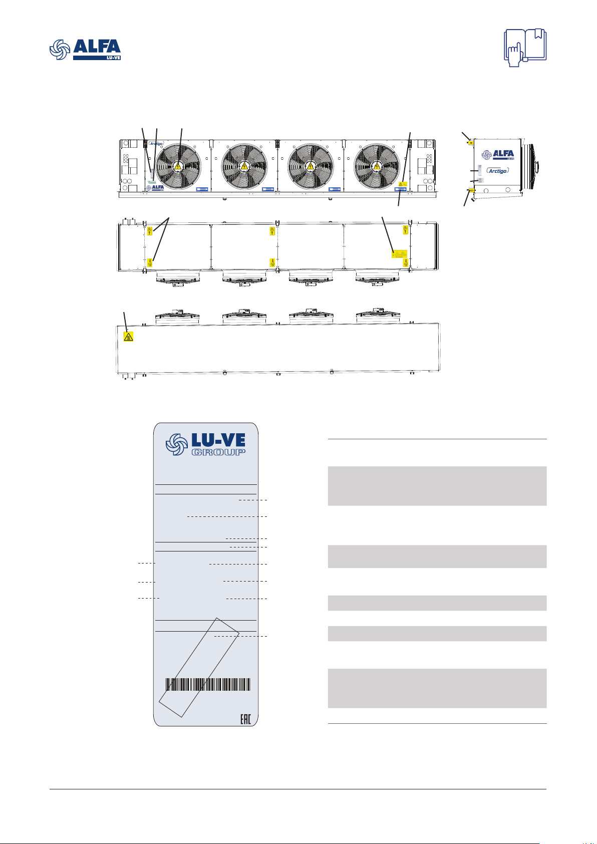
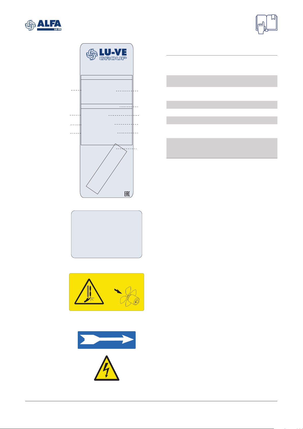
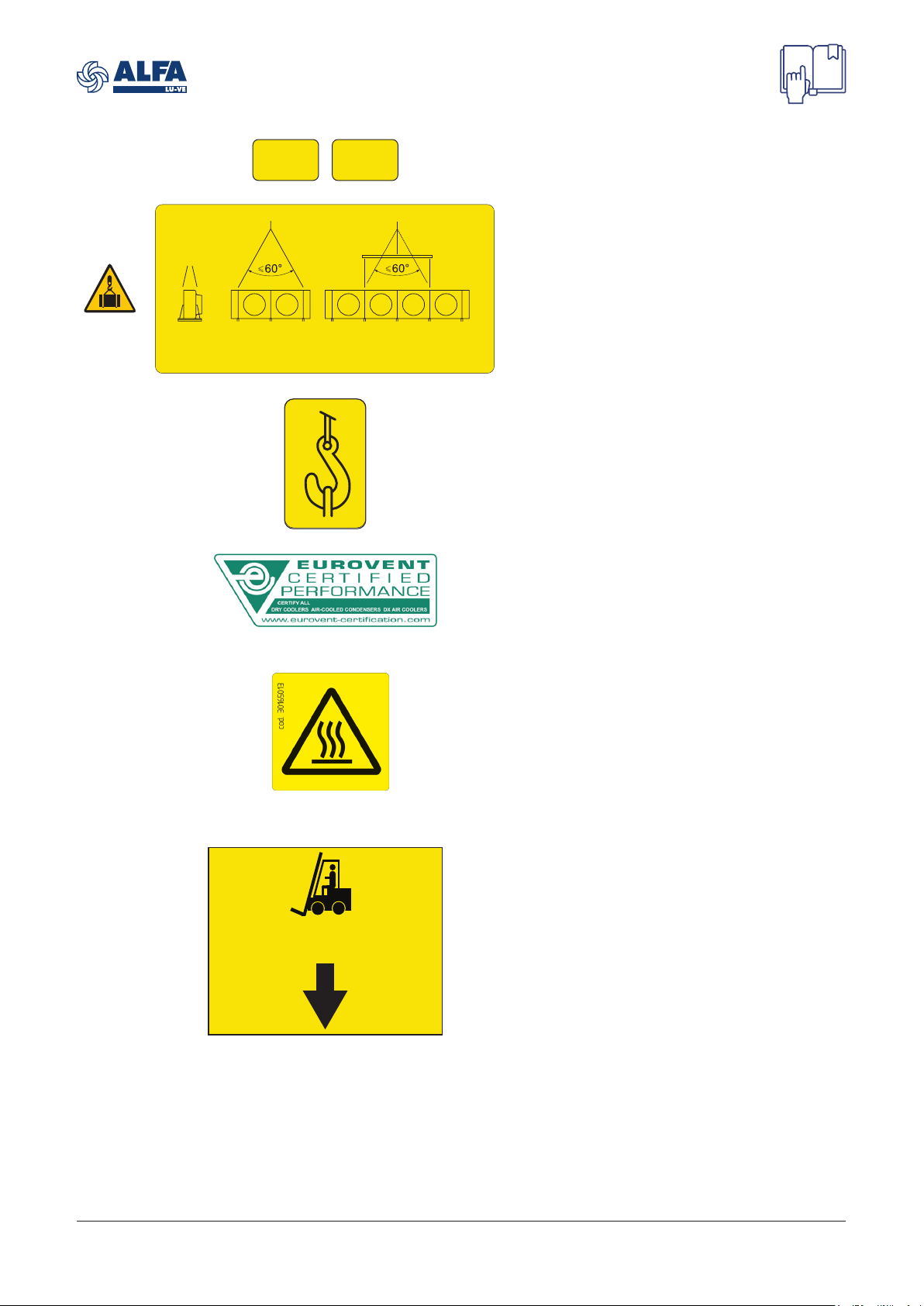
3. Product labels ......................................................................................................................... 7
4. Unpacking and lifting ........................................................................................................... 11
4.1 Standard unit .......................................................................................................................... 11
4.2 Unit with mounting feet (optional) ........................................................................................... 13
4.3 Lifting from above ................................................................................................................... 14
5. Installation ............................................................................................................................ 14
5.1 Assembly ................................................................................................................................ 14
5.2 Mounting dimensions ............................................................................................................. 15
5.3 Mounting bracket .................................................................................................................... 19
5.4 Technical spaces .................................................................................................................... 19
5.5 Drain line ................................................................................................................................ 20
5.6 Electrical connections ............................................................................................................. 20
5.7 Hot-gas defrost ....................................................................................................................... 21
5.8 Hot gas and hot water connection .......................................................................................... 23
6. Maintenance .......................................................................................................................... 24
6.1 Fan replacement .................................................................................................................... 24
6.2 Driptray ................................................................................................................................... 24
6.3 Side covers ............................................................................................................................. 26
6.4 Coil defrost heater elements replacement (optional) .............................................................. 26
6.5 Driptray heater elements replacement (optional) ................................................................... 26
6.6 Shut up sock mounting (optional) ........................................................................................... 27
6.7 Suction hoods mounting (optional) ......................................................................................... 28
7. Spare parts ............................................................................................................................ 30

31466441EN-00
3
Alfa LU-VE is a trademark registered and owned by LU-VE Group.
Alfa LU-VE reserves the right to change specifications without prior notification.
1 Important information
1.1 Disclaimer
This Instruction Manual applies to all Arctigo ISD industrial air cooler products and is supplied in
combination with the Air Cooler Product Manual AHE00042. Both manuals must be carefully exam-
ined and instructions should be followed up at all times. Alfa LU-VE does not accept liability for any
damage resulting from non-compliance to the instructions as given in the manuals and order-related
documents.
1.2 Intended use
Air coolers are partly completed machinery according to Machine Directive 2006/42/EC and intend-
ed for incorporation in cooling systems.
Declarations of Incorporation are available on alfa.luvegroup.com. The units may not be put
into operation until the conformity of the complete machine or cooling system has been declared
according to the following standards and directives:
• Pressure Equipment Directive 2014/68/EU
• Machine Directive 2006/42/EC
• Low voltage directive 2014/35/EU
• Electrical Equipment of Machines IEC 60204-1
• Electro Magnetic Compatibility 2014/30/EU
• Any applicable local or national legislation
1.3 Where to find product information
Detailed technical data for individual product models are available in order related documents,
on the product label and in product data sheets. Comprehensive technical information for all Alfa
LU-VE air heat exchanger products is available on-line on alfa.luvegroup.com. This includes:
• Product manuals
• Instruction manuals
• Product leaflets & brochures
• Product data sheets (selection software)
• Dimensional drawings
• Electrical wiring diagrams
• Certificates
Alfa LU-VE offers world-wide service and support. In case of any questions or uncertainty please
contact your local Alfa LU-VE representative.
Contact addresses are available at alfa.luvegroup.com.
Arctigo ISD

31466441EN-00
4
Alfa LU-VE is a trademark registered and owned by LU-VE Group.
Alfa LU-VE reserves the right to change specifications without prior notification.
2 Product description
2.1 General information and application
Arctigo ISD is a wide and flexible range of single discharge industrial air coolers for both cooling
and freezing applications in medium to large cold rooms. This industrial air cooler line has been
designed using the Helpman® heritage, to keep fresh and frozen goods refrigerated from +10 to
-40 ° C, with either high or low humidity content.
The Arctigo range offers a wide variety of cooler configurations and a long list of options, always
allowing to select the best model to suit all applications in industrial refrigeration installations.
Arctigo air cooler models are available for dedicated applications such as agricultural storage, air-
sock application or shock cooling.
• Refrigerants: HFC, ammonia, brine, CO2
• Capacity range (SC2): 3 up to 240 kW
• Air volume: 3,000 up to 130,000 m³/h
Refrigerant application Design pressure
HFC 33 bar
Ammonia 30 bar
CO233-40-60 bar
Brine 10 bar
2.2 Standard configuration
• Finned coil:
- 10 coil block modules
- 3, 4, 6, 8 or 10 tube rows deep
- Tubing ø 5/8”Cu ripple fin, smooth Cu tubing for brine or smooth stainless steel
- Tube pitch 50 mm square
- Corrugated Alu-fins
- Fin spacings 4, 5, 6, 7, 8, 10 and 12 mm
• 1 to 6 Fans, ø 400 mm up to ø 910 mm, drawing trough the coil. Power supply 400/50-60/3 or
230/50-6-/1 (ø 400 and 450 mm), two noise levels (Δ/Y connections).
AC/EC fan motors with dynamically and statically balanced external rotors, manufactured in
accordance with VDE 530/12.84 IP54 class F. Integrated thermo contacts (Clickson) provide reli-
able protection against thermal overload.
• Corrosion resistant materials: coil frame and casing pre-galvanized sheet steel, epoxy coated
RAL 9003. All fixing materials stainless steel.
• Hinged side panels and driptray, drain(s) 1½" BSP external
• Fitted with schräder valve on the suction connection for testing purposes.
• Refrigerant connections right or left (L=default).
• Sufficient room for fitting the expansion valve inside.
• Suitable for dry expansion or pumped system.
• Stickers indicate fan direction and refrigerant in/out.

31466441EN-00
5
Alfa LU-VE is a trademark registered and owned by LU-VE Group.
Alfa LU-VE reserves the right to change specifications without prior notification.
2.3 Options
• Connection box (CB)
• Connection box with single switch for all fans (CB1)
• Shut up sock (S)
• Sock Ring (SR)
• Electric defrost systems:
-Electric defrost in driptray + hot gas in coil (E1)
-Electric defrost heavy (E2)
-Electric defrost light (E4)
• Hotgas defrost systems:
-Hotgas defrost (HG)
-Hotgas defrost, connected (HGC)
• Hot water defrost (HW)
• Stainless steel casing and coil frame (SSC). Standard materials for underplate (aluminium) and
fan grid (black painted steel).
• Alternative fin materials (SWR / EP)
• Dual fin spacing (DF) - on request
• On/off switch (SW)
• Motorized defrost damper
• Threaded connections (T) - for brine models
• Top connections (AVA) - for brine models
• Slip-on flanges aluminium PN16 for copper tubes models or stainless steel PN16 stainless steel
tubes models (F) - for brine models
• Fan casing 90° (FC1)
• Fan casing 45° (FC2)
• Suction hood 90° (H1)
• Suction hood 45° (H2)
• Insulated suction hood 90° (IH1)
• Insulated suction hood 45° (IH2)
• Hinged fan ring (HF)
• Insulated drip tray (I2)
• Mounting feet (MF)
• Fan ring heater (FRH)
• Streamer (ST) - not available for 400 and 910 mm fan units

31466441EN-00
6
Alfa LU-VE is a trademark registered and owned by LU-VE Group.
Alfa LU-VE reserves the right to change specifications without prior notification.
2.4 Code description
ISD 71 1 - 20 S A C E A 33 AL 7 - AB 5 4 - AB D - L FRH
1 2 3 4 5 6 7 8 9 10 11 12 13 14 15 16 17 18 19
1 Arctigo industrial air cooler single discharge - air direction draw-through
2 Fan diameter (40=400, 45=450, 50=500, 63=630, 71=710, 80=800, 91=910 mm)
3 Number of fans (1 to 6)
4 Tubes per row
5 Coil module (blank=standard coil module, S=short coil module)
6 Tube rows code (A=3 B=4 C=6 D=8 E=10)
7 Tube material (C=copper, S=stainless steel)
8 Application (E=direct expansion, PB=pumped bottom feed, PT=pumped top feed, blank for
brine units)
9 Refrigerant system (H=HFC, A=ammonia, W=brine, X=CO2)
10 Maximum working pressure
11 Fin material (AL=aluminium, EP=precoated aluminium, SWR=sea water resistant aluminium)
12 Fin spacing (4=4.0, 5=5.0, 6=6.0, 7=7.0, 8=8.0, 0=10, 2=12 mm)
13 Number of circuits (2 digits)
14 Capillary diameter (1 digit: for brine and pump there is X, for DX there is 4, 5 or 6)
15 Orifice diameter (mm, only for NH3units)
16 Fan motor code (2 digits)
17 Fan digit (D or Y for AC 3ph, S for AC 1ph, E for EC)
18 Refrigerant connection side (L=left, R=right - fan side view)
19 Options

31466441EN-00
7
Alfa LU-VE is a trademark registered and owned by LU-VE Group.
Alfa LU-VE reserves the right to change specifications without prior notification.
3 Product labels
HELPMAN
HELPMAN
Manufactured by
AIR HEX ALONTE S.R.L.
via delle Albere 5, 36045, Alonte(VI)
HEAT EXCHANGER
ISD632-166CEX60SR444M8YL
Code:
ARCTIGO
Manuf. Date: Net Weight ±5%:
09-2021 387,198 Kg
PED CAT ART 4.3
Max DN: Fluid Group:
15
2
PS min/max: PT:
-1/60.0 bar 90 bar
TS min/max: Test Date:
-60/125 °C 09-2021
ELECTRICAL DATA
Fan motors qty: 2
Power Supply: 400V/T/50
8166445
Cust. Code:
MADE IN ITALY
EXAMPLE
EXAMPLE
1. Product label
Model Refer to paragraph "2.4
Code description"
Product code Communicate this when
ordering spare parts as
they identify the unit
Unit Net Weight Check before any lifting
operation to ensure that
proper lifting tools are used
PED Category According to PED
Max DN Maximum diameter of the
distributor tube
Fluid Refrigerant
Ps Design pressure
Pt Test pressure
Coil Ts Range of operating tem-
peratures for the coil
Test date Date on which the coil has
been pressure tested in the
factory
No Motors Number of fans
Product code
Fluid
No. Motors
PED category
Model
Pt
Test date
Weight
Ts
Ps
Max DN

31466441EN-00
8
Alfa LU-VE is a trademark registered and owned by LU-VE Group.
Alfa LU-VE reserves the right to change specifications without prior notification.
2. Product label - coil
Product code
Product serial nr.
Communicate these when
ordering spare parts as
they identify the unit
PED Category According to PED
Max DN Maximum diameter of the
distributor tube
Fluid Refrigerant
Ps Design pressure
Pt Test pressure
Coil Ts Range of operating tem-
peratures for the coil
Test date Date on which the coil has
been pressure tested in the
factory
5.307
AT TENZIONE!
CIRCUITO FRIGORIFERO PRECARICATO CON AZOTO
WARNING!
PRECHARGED REFRIGERANT CIRCUIT WITH NITROGEN
ACHTUNG!
VERLADTER KÄLTEMITTELKREISLAUF MIT STICKSTOFF
AT TENTION!
CIRCUIT FRIGORIFIQUE PRE-CHARGE AVEC AZOTE
BHИМАНИЕ!
СИСТЕМА ЗАПРАВЛНА АЗОТОМ
3. Nitrogen precharge warning
Units are delivered from the manufacturer
with an overpressure. Check pressure on
the Schrader valve. With unpressurised unit:
Immediate report to manufacturer and note on
bill of delivery.
Manufactured by
AIR HEX ALONTE S.R.L.
via delle Albere 5, 36045, Alonte(VI)
HEAT EXCHANGER
Coil Code:
**********
Manuf. Date:
09-2021
PED CAT ART 4.3
Max DN: Fluid Group:
15
2
PS min/max: PT:
-1/60.0 bar 90 bar
TS min/max: Test Date:
-60/125 °C 09-2021
SN: 8166445
Product Code:
ARCTIGO
ISD632-166CEX60SR444M8YL
MADE IN ITALY
EXAMPLE
EXAMPLE
4. Warning sign for fans and fan type
Airflow direction:
D= draw-through
Rotation direction:
L= left
R= right
Type DL
5. Fan rotation
Sticker indicates fan rotation direction.
6. Electrical warning
Electrically powered component. Switch off
power supply before any maintenance or instal-
lation activity.
Fluid
Product
Serial nr.
PED category
Pt
Test date
Product code
Coil code
Ts
Ps
Max DN

31466441EN-00
9
Alfa LU-VE is a trademark registered and owned by LU-VE Group.
Alfa LU-VE reserves the right to change specifications without prior notification.
9. Lifting from above
Preferably use hoisting beams when lifting from
above.
Use all marked lifting lugs
10. Lifting lug
Use all marked lifting lugs when lifting from
above.
11. Eurovent
Sticker is applied when the product is included
in the Eurovent Certify All program.
7/8. In/Out
Refrigerant connections inlet and outlet.
IN
OUT
12. Hot surface
Danger of burns. Wear adequate protection.
FORKLIFT
cod. 31703662
Forklift
Sticker is applied on the pallet or on horizontal
beam (MF option). Insert forks where indicated.

31466441EN-00
10
Alfa LU-VE is a trademark registered and owned by LU-VE Group.
Alfa LU-VE reserves the right to change specifications without prior notification.
cod. 31703660
50 mm
cod. 31703661
50 mm
Unit handling - standard unit
Sticker is applied on the packing.
Unit handling - MF option
Sticker is applied on the packing.

31466441EN-00
11
Alfa LU-VE is a trademark registered and owned by LU-VE Group.
Alfa LU-VE reserves the right to change specifications without prior notification.
Always follow guidelines and instructions as given in the air cooler product manual AHE00042.
Arctigo air coolers are delivered in mounting position, mounted on wooden beams. Handling and
positioning can take place with use of a forklift.
Insert the forks under the lower pallet.
In order to avoid damage to the driptray or falling
of the unit, ensure that the lifting forks cover all
beams from the lower support pallet.
DO NOT LIFT
ON THIS
SIDE
4 Unpacking and lifting
When more coolers are delivered in a single
shipment, packed air coolers may be stacked
during transportation (max. 2 units). Packed air
coolers are to be unloaded one by one. Units
must be unloaded and handled only from the
long side, one at a time.
When possible, casing options are supplied
mounted on the unit. In such cases this warning
might be present on one side the unit packag-
ing. In order to ensure safe lifting, the unit must
be loaded on the heavier side i.e. the one where
this warning sign is not present.
4.1 Standard unit
Place the unit on the ground and loosen the fix-
ing materials from the top pallet.
50 mm

31466441EN-00
12
Alfa LU-VE is a trademark registered and owned by LU-VE Group.
Alfa LU-VE reserves the right to change specifications without prior notification.
Remove the top pallet.
Insert the forks under the lower pallet.
Lift the unit into mounting position and secure
following instructions given in chapter "5
Installation".
Once the unit is secured in the installation posi-
tion, loosen the fixing materials from the lower
support pallet.
Remove pallet.

31466441EN-00
13
Alfa LU-VE is a trademark registered and owned by LU-VE Group.
Alfa LU-VE reserves the right to change specifications without prior notification.
Place the unit on the ground and loosen the fix-
ing materials from the top pallet.
Remove the top pallet.
In order to avoid damage to the driptray while handling, packing of units with mounting feet includes
horizontal beams under the unit. Insert the forks under the horizontal beams.
Ensure that the lifting forks cover the horizontal beams.
4.2 Unit with mounting feet (optional)
50 mm
Unscrew the fixing materials from the lower sup-
port pallet and support triangles.

31466441EN-00
14
Alfa LU-VE is a trademark registered and owned by LU-VE Group.
Alfa LU-VE reserves the right to change specifications without prior notification.
When unit lifting from above is required, follow
the lifting instructions in the air cooler product
manual AHE00042.
Handle and position the unit by inserting the
forks under the horizontal beams.
Once the unit is positioned, unscrew and remove
the horizontal beams to allow easier mainte-
nance and grant driptray accessibility.
5 Installation
Always follow guidelines and instructions as given in the air cooler product manual AHE00042.
5.1 Assembly
Air cooler units may be delivered as separate components that need to be assembled on site. This
could occur when casing options like suction hoods are selected, causing the unit to exceed the
maximum width for transportation by truck (240 cm). Depending on handling conditions on site,
assembly should take place either before or after mounting the unit to the final installation position.
When supplied in components, assembly instructions are included with the air cooler unit.
4.3 Lifting from above

31466441EN-00
15
Alfa LU-VE is a trademark registered and owned by LU-VE Group.
Alfa LU-VE reserves the right to change specifications without prior notification.
800
1600
2400
1600 1600
1600 800 1600
3200
4000
4800
1600 1600 1600
737
5.2 Mounting dimensions
Detailed drawings showing all required mounting and refrigerant connection
dimensions are available for download on alfa.luvegroup.com.
Dimensional drawings
Arctigo ISD
ISD 40-45S

31466441EN-00
19
Alfa LU-VE is a trademark registered and owned by LU-VE Group.
Alfa LU-VE reserves the right to change specifications without prior notification.
5.3 Mounting bracket
M10 stud (minimum)
Washer
Lock nut 12
24
Use extra wide washer (ISO 7093) when mount-
ing the unit to the ceiling.
Avoid any lateral torque on the mounting brack-
ets.
5.4 Technical spaces
The following guidelines are to be respected when positioning air cooler units.
Minimum wall distance on suction side.
Minimum space for defrost heater replacement
(optional). Side for defrost elements extraction is
opposite to the connections.
Adequate spacing for driptray opening shall be
left below the cooler.
D ≥ Hcoil
D
Hcoil
D
D D
Minimum space for side panels opening.
D > 737 mm
L
D > L
D > Wdriptray +100
Wdriptray

31466441EN-00
20
Alfa LU-VE is a trademark registered and owned by LU-VE Group.
Alfa LU-VE reserves the right to change specifications without prior notification.
5.6 Electrical connections
The following data determine which connection diagram is to be selected and respected for electri-
cal installation:
• Heat exchanger model indication
• Fan motor type
• Electrical options
Electrical connection diagrams are available for download on alfa.luvegroup.com.
When in doubt always contact your local Alfa LU-VE representative for assistance.
5.5 Drain line
The drain line diameter must be at least the size of the driptray drain diameter and should be laid
with an adequate slope. For room temperatures below 0° C drain line insulation and an internal or
external heating element are required to prevent freezing.
Tighten drain connection by using two wrenches.
Keep wrenches firmly to not strain on connection
welding.
A syphon must be installed on the drain line,
outside the cold room.
Optional drain kit for PVC click-on connection
including adapter, O-ring and 40 mm 45° PVC
connection, freely adjustable into either horizon-
tal or vertical position.
Electrical connections
Arctigo ISD
Other manuals for LU-VE Arctigo ISD
1
Table of contents
Other Alfa Network Air Conditioner manuals