Figure 5
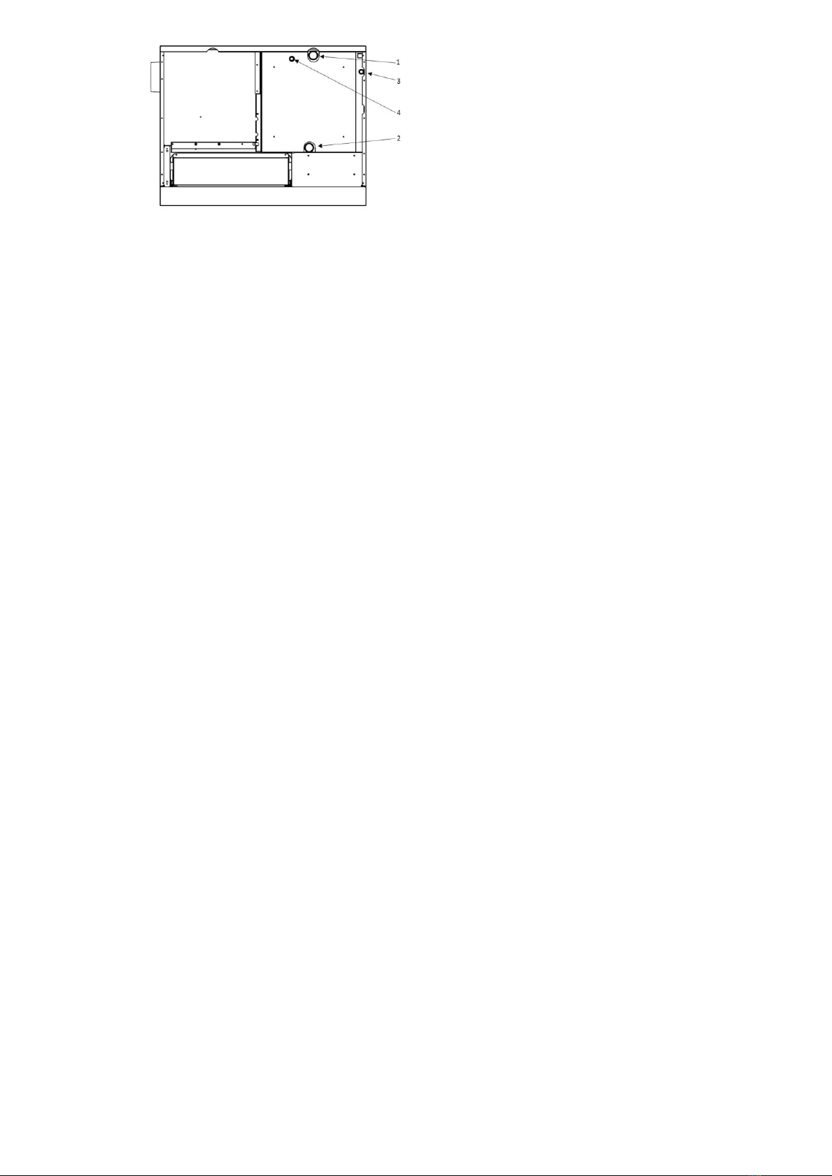
6.1 FLOW PIPE AND RETURN PIPE (Fig. 5, pos. 1 and 2 and Fig. 7, pos. 18 and 19, Fig. 8, pos. 13 and 14)
The size of the flow pipe and return pipe outlets is 5/4”and may not be reduced or tapered before the first
branch. Use steel 5/4’’ pipe or copper pipe with external diameter Ø32mm (or larger).
While installing the system, absolutely make sure that pipe slopes are 0.5% (5 mm per one meter of pipe length)
and that the air is released from the system (from the boiler, pipes, radiators).
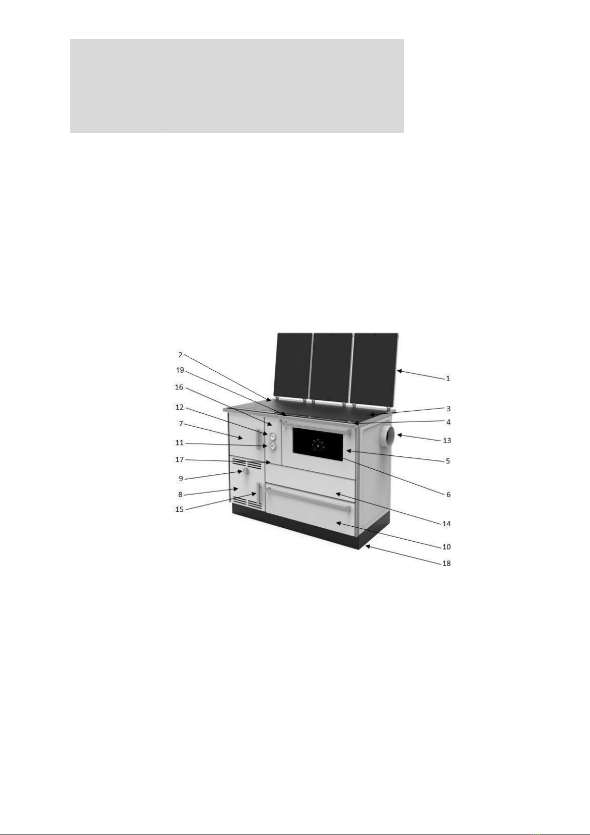
You can install a combination of temperature and pressure gauge on the flow pipe, although both thermometer
and pressure gauge are installed at the front of the cooker.
On the return pipe, install a pump, expansion vessel and a spigot for filling and discharging of the system. When
you install the pump, take note of the pump’s direction.
6.2 THERMAL RELEASE VALVE WITH INSTALLED THERMAL PROTECTION AND ADDITIONAL
CONNECTION ELEMENTS
For the purpose of installation of the thermal release valve, you should procure and install the following:
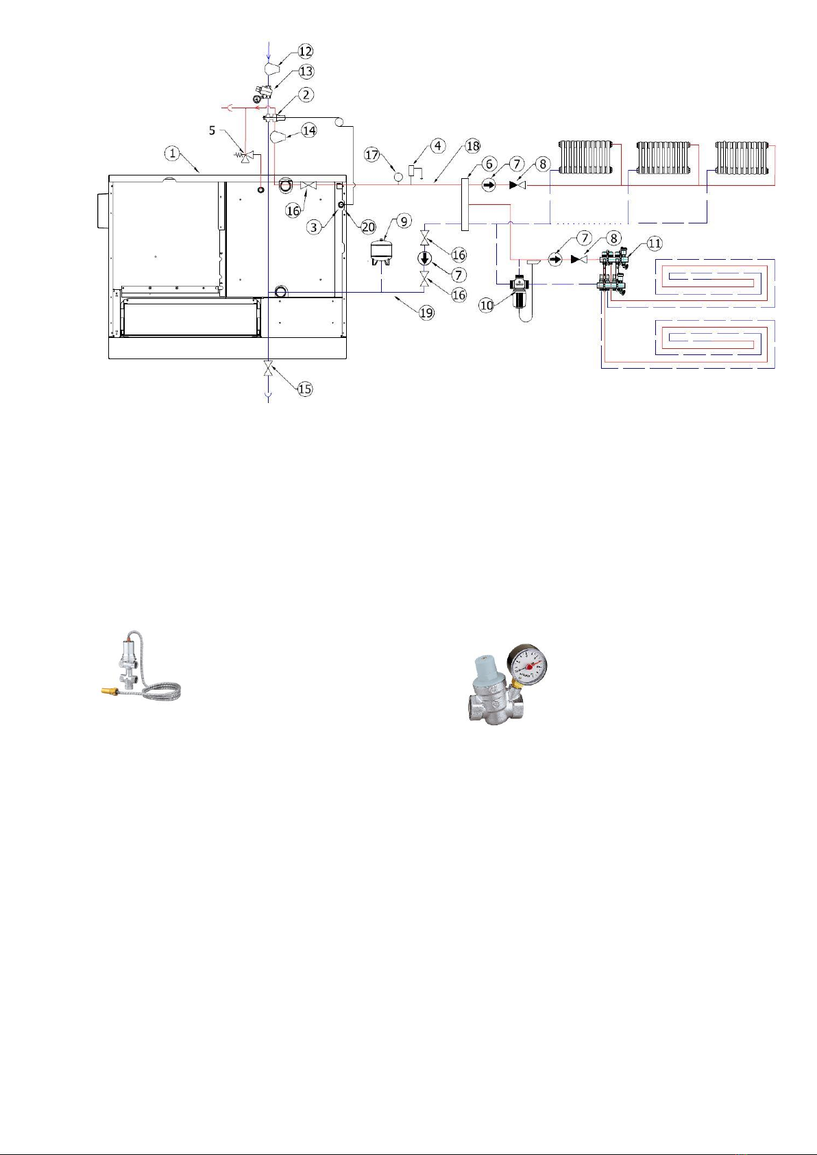
1. Thermal release valve with built-in thermal protection type 544, 1/2”, Caleffi product (Fig. 7a) and Fig. 7, pos.
2. Slope pressure regulator 1/2”with manometer, the same or similar as shown in Fig. 7b and Fig. 7, pos. 13.
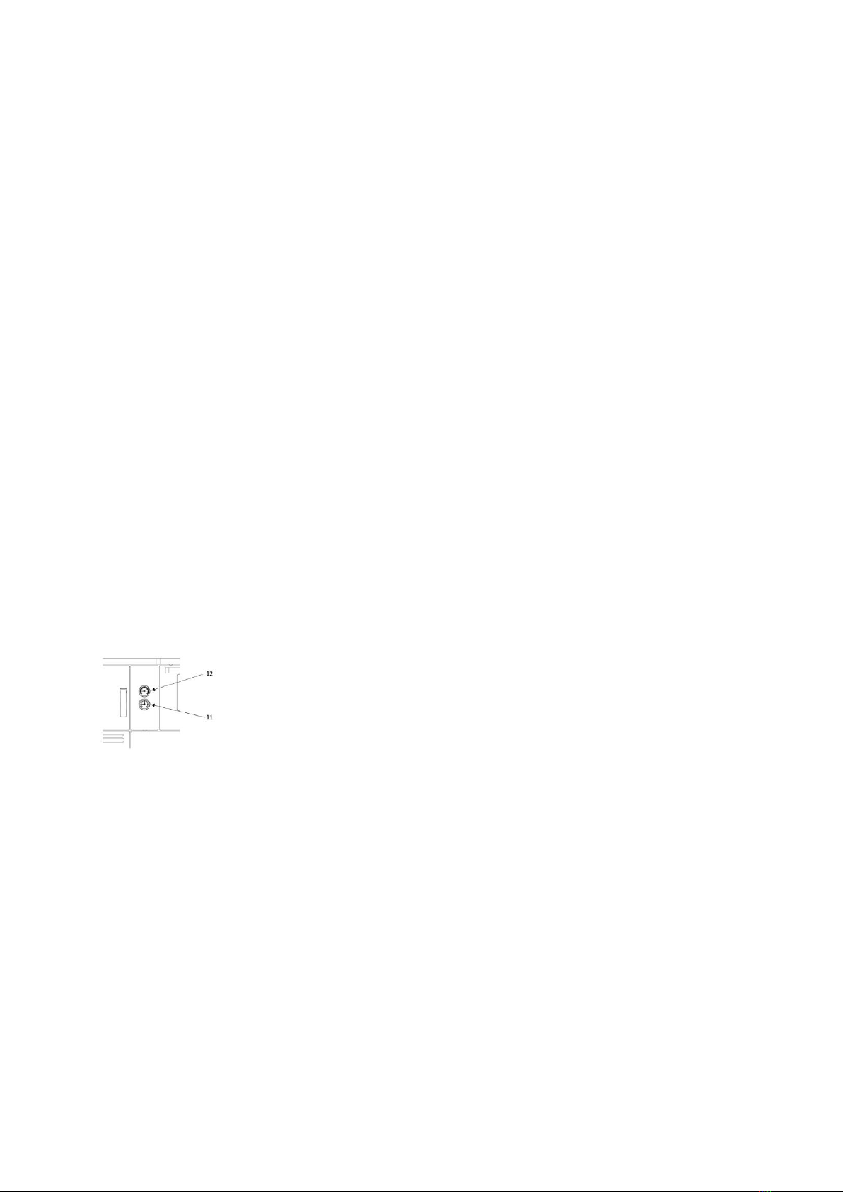
3. Filter for cold water at the input of the water supply to the thermal valve, Fig. 7, pos. 12.
4. Filter for hot water intake of the boiler and water outlet of thermal valve, Fig. 7, pos. 14.
Note:
These components are not included with the product for local heating you purchased!
Installation of thermal release valve with built-in thermal protection (Fig. 7, pos. 2 and Fig. 7a) with additional
elements ensuring safe operation, such as pressure regulator (Fig. 7, pos. 13 and Fig. 7b), water filter on the
boiler intake (Fig. 7, pos. 12) and water filter on the boiler outlet in closed central heating system is
MANDATORY. This specially refers to a closed system, when the radiators are submerged and where in case of
termination of the pump operation for any reason, the water temperature in the boiler rapidly increases and
overheating occurs very quickly.
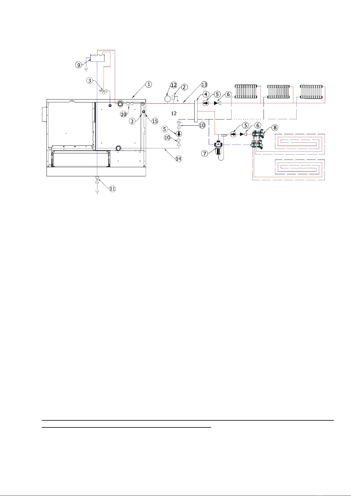
In the open central heating system, the installation of thermal fuse is not mandatory.
6.2 THERMAL RELEASE VALVE WITH INSTALLED THERMAL PROTECTION (Fig. 7, pos. 2 and Fig. 7a)
Thermal release valve should be installed near the cooker, depending on the available space. It can be installed
in any position. You should take into account the direction of cold water intake and hot water outflow from the
boiler which is clearly marked on the valve body.
The thermal release valve probe (Fig. 7, pos. 3) is best be placed in the thermal valve connection on the boiler
itself (Fig. 7, pos. 20). It can be placed on the discharge - distribution pipe (Fig. 7, pos. 18), but at a distance
from the boiler of 500 mm the most or at the highest point of the boiler before the exhaust pipes.
Seal it with hemp or other sealing material by tightening.
Figure 7 shows the connection diagram for the thermal release valve.
The device is made in one piece with thermal release valve and filling valve.
Valve opening temperature is 100°C (+0°C/-5°C).
The fluid recommended in the installation is water and 30% glucose antifreeze.
Note:
At reaction, i.e. valve operation, during fluid cooling in an overheated boiler, part of the new fluid is injected into
the boiler, but the part is also ejected from the boiler. It will be poured down the drain. If the antifreeze is in the
installation, you must keep in mind that a certain percentage will go out and pour down the drain!
It is recommended to use the thermal release valve Caleffi type 544, 1/2”as shown in Figure 7a.
6.2.2 SLOPE PRESSURE REGULATOR 1/2”WITH MANOMETER (Fig. 7, pos. 13 and Fig. 7b)
When installing the thermal release valve, it is mandatory to install a slope pressure regulator as shown in the
Figure 7, pos. 13. The pressure that is maintained by pressure regulator must be set at a higher pressure than
the pressure that is in the heating system. If you do not have a higher water pressure of at least 0.8 bar
compared to the pressure in the heating system, the thermal release valve will not work or cannot inject cold
water into the boiler that needs to be cooled.
Pressure regulator should be set to 2.8 to 3 bars.