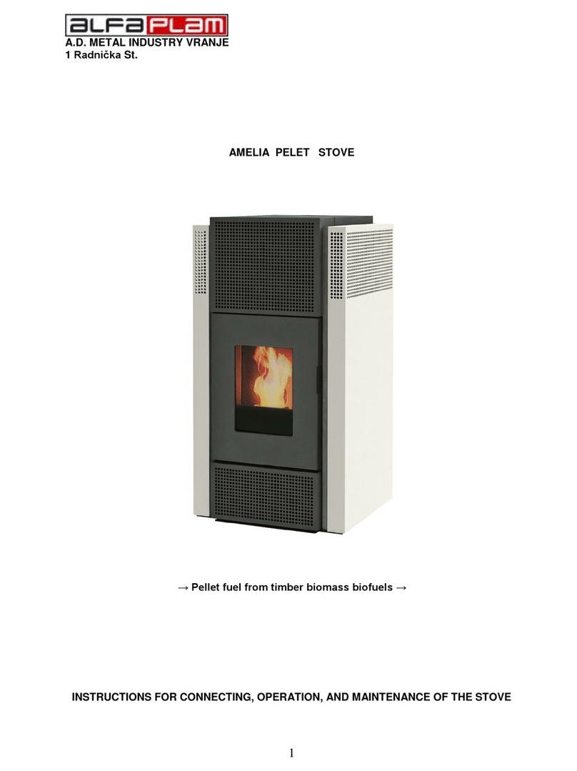
Alfa Plam DINO 27 Quick start guide

1612511
17500 VRANJE, SERBIA
1 Radnička St., Telephone: +381 17 421 121
PELET STOVE FOR CENTRAL HEATING
„DINO 27”
→Pellet fuel from timber biomass biofuels →
INSTRUCTIONS FOR CONNECTING, OPERATION, AND MAINTENANCE OF THE STOVE
This product meets the requirements of the Ecodesign Directive in terms of efficiency and air pollution level,
in order to contribute to the reduction of energy consumption and negative environmental impact.
ENG_v.1.2

DINO 27 PELET STOVE FOR CENTRAL HEATING
Heating devices (in this manual they are called “stoves") by Alfa Plam (in this manual titled Alfa Plam) are assembled and
tested in accordance with the safety and applicable measures, and regulations of the European Community.
This manual is intended for users of the stoves, contractors who install the stoves, operators and workers for stove
maintenance that is shown on the front page of the manual.
If you do not understand something in this manual, please contact our professional services or an authorized service
center. In doing so, always specify the number of the chapter where there is some ambiguity.
Printing, translation and reproduction, even in part, of this manual is subject to licensing by Alfa Plam, which means that
Alfa Plam must approve these actions. Technical information, figures, and specifications in this manual must not be given to
a third party.
WARNING:
IMPORTANT: Connecting the appliance to the electrical installation must be carried out by qualified and authorized persons
in accordance with applicable regulations.
This appliance is not intended for use by persons (including children) with reduced physical, motor, and mental capabilities,
or to persons with a limited knowledge and experience in the absence of the person responsible for their safety or care.
Children cannot be allowed to play with this appliance.
DOUBLE COMBUSTION SYSTEM
The flame obtained by proper combustion of the pellet in the stove emits the same amount of carbon dioxide (CO2), which
would be freed as a result of the natural decay of wood.
The amount of carbon dioxide (CO2) obtained through combustion or decomposition of plant mass corresponds to the
amount of carbon dioxide (CO2) which the plant mass is able to obtain from the environment and to transform it into air and
carbon of the plants during its entire lifetime.
The use of non-renewable fossil fuels (coal, oil, gas), contrary to what happens with the wood, releases into the atmosphere
huge amounts of carbon dioxide (CO2), that have been gathering up for millions of years, creating a greenhouse effect. The use
of wood as fuel is therefore perfectly balanced with the environment, because the wood as a renewable fuel is in ecological
harmony with nature.
Using the principle of clean combustion, we fully achieve these objectives, and so Alfa Plam has directed its development
and all activities towards fulfilling this goal.
What do we consider clean combustion and how does it work?
Controlling and adjusting the primary air and injecting the secondary air causes secondary combustion, or the so-called
post-combustion, which provides a secondary flame that is by its nature lighter and stronger than the primary flame. The
addition of a new oxygen (inserted through the air) allows further combustion of gases that are not completely burned. This
significantly increases the thermal efficiency and reduces harmful emissions of carbon monoxide (CO), because the
incomplete combustion is minimized. These are the basic characteristics of these stoves and other products of Alfa Plam.

0.0. TECHNICAL CHARACTERISTICS OF THE STOVE
1. Dimensions of the stove:
- width
574 mm
- depth
568 mm
- height
1237 mm
2. Flue terminal diameter
80 mm
3. Diameter of exterior air intake on the wall
100 mm
4. The height from the floor to the axis of the flue terminal
380 mm
5. Maximum stove power (radiation of water included)
26,9 kW
6. Radiation stove power at maximum power
2,4 kW
7. The power of a water heater at maximum power
24,5 kW
8. CO (at 13% O2) emissions at maximum power
48 mg/m3
9. Flue gas mass flow at maximum power
14,6 g/s
10. The maximum consumption
5,847 kg/h
11. Degree of efficiency at maximum power
93,5 %
12. Minimum stove power (radiation of water included)
8,4 kW
13. Radiation stove power at minimum power
1 kW
14. The power of a water heater at minimum power
7,4 kW
15. The minimum consumption
1,78 kg/h
16. Degree of efficiency at minimal power
95 %
17. CO (at 13% O2) emissions at minimum power
122 mg/m3
18. Flue gas mass flow at minimum power
7,2 g/s
19. Optimal draft
12 Pa
20. Heating volume
335 - 447 m3
21. The capacity of the funnel-like fuel reservoir
45 kg
22. The maximum working time with a full reservoir
25,3 h
23. The minimal working time with a full reservoir
7,7 h
24. Boiler water volume
32 l
25. Maximum output power
450 W
26. Voltage and frequency
230V / 50Hz
27. The weight of the stove:
-net
193 kg
-gross
222 kg

Contents:
THE TASK PURPOSE OF THIS MANUAL.......................................................................................................1
UPDATING THE INSTRUCTIONS ...........................................................................................................1
RESPONSIBILITIES OF THE MANUFACTURER .............................................................................................1
GENERAL CHARACTERISTICS OF USERS..............................................................................................1
TRANSPORTING AND USING THE STOVE - HANDLING.........................................................................1
RESPONSIBILITIES OF THE INSTALLER................................................................................................1
INSTALLATION –STOVE INSTALLATION ....................................................................................................2
INSTALLING THE STOVE ......................................................................................................................2
THE SMOKE EXHAUST SYSTEM ...........................................................................................................2
INSULATION AND THE DIAMETER OF THE OPENING (HOLE) ON THE ROOF (OR IN THE WALL) ............4
COMBUSTION AIR SUPPLY (Figure 8) ..................................................................................................6
CONNECTING THE POWER ...................................................................................................................6
IMPORTANT INSTRUCTIONS.......................................................................................................................7
WARNING SAFETY MEASURES FOR STAFF MAINTENANCE ........................................................................7
WARNING SAFETY MEASURES FOR THE USER.....................................................................................7
SAFETY GUIDILINES FOR IGNITION AND CLEANING OF THE STOVE............................................................8
ROUTINE CLEANING AND MAINTENANCE DONE BY THE USER OF THE STOVE ....................................8
CLEANING AND MAINTENANCE (for employees who do maintenance) ...............................................10
SPECIAL MAINTENANCE ....................................................................................................................10
IMPORTANT SAFETY INFORMATION.........................................................................................................10
THE PELLET QUALITY IS VERY IMPORTANT .............................................................................................11
STORING THE PELLET ........................................................................................................................11
CONNECTING THE HYDRAULIC INSTALLATIONS ......................................................................................11
PRESSURE AND RETURN PIPE ..............................................................................................................12
BUILT-IN COMPONENT OF THE STOVE .................................................................................................12
SAFETY VALVE ...............................................................................................................................12
CIRCULATION PUMP ......................................................................................................................12
AUTOMATIC AIR VALVE..................................................................................................................13
EXPANSION VESSEL.......................................................................................................................13
CHARGING AND DISCHARGING TAP ...............................................................................................13
INSTALLING AND IGNITING...................................................................................................................13
PRACTICAL INSTRUCTIONS AND TIPS FOR THE USE OF THE HEATING SYSTEM ..................................13
PELLET LOADING ..................................................................................................................................13
CONTROL SYSTEM OF THE STOVE........................................................................................................14
ELECTRIC CONNECTIONS SCHEME ................................................................................................14
CONTROL PANEL (DISPLAY) - BUTTONS AND FUNCTIONS............................................................14
MENU .............................................................................................................................................16
STOVE IGNITION AND FUNCTIONAL CONDITIONS..........................................................................21
POSSIBLE PROBLEMS AND SOLUTIONS ........................................................................................22
SAFETY MEASUREMENTS The stove is equipped with the following safety devices: .............................24
FAULTS - CAUSES –SOLUTIONS..........................................................................................................24
INFORMATION ON DISPOSAL (THROWING AWAY) AND DISMANTLING (PULLING APART) THE STOVE 25

1
THE TASK PURPOSE OF THIS MANUAL
The purpose of the instructions is to enable the user to take all the necessary measures in order to ensure safe and proper
use of the stove.
UPDATING THE INSTRUCTIONS
This manual reflects a work of art at the moment when the stove was placed on the market. Therefore, Alfa Plam does not
take into account the stoves that are already on the market with the appropriate technical documentation and considers them
as defective or inadequate after any kind of modification, adaptation or application of new technologies to newly produced
machines.
The contents of this manual should be carefully read and studied. It is necessary to strictly follow all the instructions given
in this manual. All information contained in this manual is necessary for proper connection, use, and maintenance of your
stove.
Therefore, this manual has to be carefully stored for the necessary instructions in the event of any problems or concerns.
If the stove is given or sold to another person, the new owner must also be given this instructions manual.
If you have lost your manual, the manufacturer can provide you with a new one.
RESPONSIBILITIES OF THE MANUFACTURER
In issuing these instructions, Alfa Plam accepts no civil or legal liability, direct or indirect, due to:
- Accidents caused by not respecting the standards and specifications given in this manual,
- Accidents caused by improper handling or use of the stove by the user,
- Accidents resulting from modifications and repairs, which were not approved by Alfa Plam,
- Poor maintenance,
- Unforeseen events,
- Accidents resulting from the use of spare parts that were not original or not intended for these models of stoves.
Responsibility for connecting is fully assumed by the installer - contractor.
GENERAL CHARACTERISTICS OF USERS
The user of the appliance must have the following basic characteristics:
- be an adult and responsible person,
- have a specific technical knowledge that is needed for routine maintenance of electrical and mechanical components of
the stove.
CHILNDREN ARE NOT ALLOWED NEAR THE STOVE OR TO PLAY WITH IT WHILE IT IS ON.
TRANSPORTING AND USING THE STOVE - HANDLING
When using the stove, it is necessary to be careful and not allow the stove to tilt forward. This is because the brunt of the
stove is forward.
During transportation of the stove, which has to be completely safe, make sure that the forklift has the load that is greater
than the weight of the stove that it is supposed to lift. Avoid twitching and jerking movements.
ALL PACKAGING SHOULD BE REMOVED SO THAT IT IS OUT OF REACH OF CHILDREN, BECAUSE THE MATERIALS THAT
ARE INSIDE CAN LEAD TO CHILDREN SUFFOCATING. THESE INCLUDE PLASTIC BAGS, FILM, POLYSTYRENE, ETC.
RESPONSIBILITIES OF THE INSTALLER
Installer's responsibility is to do all the tests of the flue pipeline, air supply, and all the things that are necessary for
connecting (installing) your stove.
Installer's responsibility is to adjust the stove to local regulations which apply where the stove is connected (installed).
The use of the stove must be in accordance with the instructions for use and maintenance, as well as with all the security
standards that are given by the local regulations that apply where the stove is connected (installed).
The installer has to check:
-the type of stove to be connected,
- whether the room corresponds to the stove where the stove will be installed, which is expressed as the minimum size
required for installation, set forth by the manufacturer of the stove,
- heat generator
- manufacturer's instructions regarding the requirements of smoke removal systems (ducts and pipes for
smoke exhaust),
- inner cross section of the chimney, the material out of which the chimney is made, uniform cross section,
- that there are no disturbances and obstacles in the chimney,
- height and vertical extension of the chimney,
- altitude at the place of connecting the stove,
- the existence and suitability of the protective cover for the chimney that is resistant to the wind,
- the possibility of securing the external air supply and the size of the necessary openings,
- simultaneous use of stove that needs to be connected with other equipment that already exists at that
place.
If the results of all checks are positive, then we can proceed with connecting the stove. Make sure you follow the
instructions of the manufacturer of the stove, as well as the standards for fire protection and the safety standards provided.
When you are finished connecting, the stove has to be turned on in trial mode for at least 30 minutes to test if the stove is
working properly.
When the installation and important details are completed, the installer must provide the client the following:

2
- Instructions for use and maintenance issued by the manufacturer of the stove (if such instructions are not provided with
the stove),
- The documentation necessary to comply with the existing standards.
INSTALLATION –STOVE INSTALLATION
Responsibility for the work carried out at the place of connection is entirely on the user.
Before one turns the stove on, the installer must meet all legal standards of safety, as well as the following requirements:
- to check that setting up the stove complies with local, national, and European regulations,
- that the location of setting up the stove meets the requirements set forth in this manual,
- to set up the flue pipes,
- that air intake matches the type of the installed stove,
- that the electrical connections are not set up using temporary and/or not insulated electrical cables,
- to evaluate the effectiveness of grounding electrical systems,
- to always use personal protective equipment and all means of protection that are prescribed by local regulations,
- to always provide sufficient service space required for any maintenance and repair of stoves
INSTALLING THE STOVE
We recommend you to unpack the stove only when the stove is set up in the position where it will be connected.
The stove is on the plastic pins that have M10 bolts (4 items), that are threaded into the stove base. At the screws there
are M10mm threaded nuts to the plastic parts. The legs are wound up all the way to the base of the stove. After unpacking the
stove, when you put it in a place where it will be located, it is necessary to unscrew all the legs, so that a total height from the
floor to the base of the stove is about 25mm. When you are done with nivelation of the stove that needs to stand horizontally,
tighten the nuts with a 17 wrench, which needs to approach the base of the furnace, and at the same time hand-holding the
plastic part of the legs, tighten the nut. The height of about 25mm from the floor to the base is needed for better circulation of
air and cooling the stove. In this way you protect the stove from overheating and you extend its life.
If the surrounding walls and/or floors are made of materials that are not resistant to heat, then one should use adequate
protection using the insulating material that does not burn.
In order to protect the building construction against the risk of fire, flammable elements (such as walls, doors, furniture, home
appliances…) must be kept on the safe distance from the stove: 100 mm from the rear side, 200 mm from the lateral sides and
800 mm from the front side. Always leave at least 100 mm between the rear side of the stove and the wall to allow for proper
air circulation, or for the air to flow properly in that area. To protect the floor if it is made of combustible materials (wood,
parquet, linoleum, laminates, carpets…), we suggest you put a metal plate under the stove on the floor with the thickness of 3-
4 mm that will stretch 300 mm in front of the stove. Any elements made from wood (e.g. beams) or other combustible material
located near the stove should be protected/covered with fireproof material.
Leave enough clearance for maintenance work.
If the stove is installed in a kitchen with a trellis for drawing out air or if it is placed in the room with appliances that use
solid fuel (such as a wood burning stove), always make sure that the amount of inlet air in the room is sufficient to ensure safe
operation of the stove.
If a smoke channel goes through the ceiling, it should be properly thermally insulated using the protection out of insulating
materials that does not burn. When the stove is set up into place, it should be levelled using pins.
DANGER !
The exhaust gas Armour must not be connected to:
- the smoke pipe used by another heat generator (boilers, furnaces, fireplaces, stoves, etc.),
- the air drawing system (grilles, ventilation openings, etc), even if the system is inserted into the drain pipe.
DANGER !
It is forbidden to install shut-off valves for the flow (draft) of air (flap valves that can prevent airflow or disable drafts).
ATTENTION
If the ejection path of smoke creates such a bad draft, of a bad flow of air (many curves, improper completion of the ejection
of smoke, constriction, etc.) discharge of smoke can be bad, or in a situation like this smoke discharging is not as good as it
could be.
The smoke ejection system from the stove operates under negative pressure in the stove chamber and with mild pressure
from the smoke drain pipe. It is very important that the smoke extraction system is hermetically closed (sealed). This requires
the use of a smooth tube on the inside. First of all you must carefully study the plan and structure of the room when the smoke
extraction pipe is set up through the walls and roof, so that the installation of pipes is performed properly in accordance with
the standards of fire protection.
You should first ensure that the room where the stove is located has enough air for combustion. It is advisable to
periodically performs check so as to ensure that the combustion air comes right up to the combustion chamber. The stove
operates at 230 V ~ 50 Hz. Make sure that the electrical cord is not underneath the furnace, to be away from the stove, to be
away from hot spots, and not to touch any sharp edges that it could interdict. If the stove is electrically overloaded, this can
lead to shortening of the lifetime of the electronics of the stove.
Never turn off the power supply by pulling the plug when there is a burning flame in the stove. This could jeopardize the
proper functioning of the stove.
THE SMOKE EXHAUST SYSTEM
The smoke exhaust must be carried out in accordance with existing standards. Exhaust gas tube should be well sealed
(see Figures 1-7).
For smoke exhaustion, one can also use classic brick chimneys while flues can also be made of pipes that need to be well
insulated (double wall) and sealed, to avoid creating condensation in them.
The drain tube absolutely must not be connected to other systems of any kind, such as the systems where the smoke is
removed from the combustion chamber, exhaust grilles or air distribution system, etc. Also, the smoke exhaust must not be
3
set up in enclosed or semi-enclosed areas such as garages, narrow corridors, underground passages, or at any other places
where they is smoke. When the stove is connected to the exhaust gas pipeline, it is necessary to bring professional
chimneysweep to verify that the chimney does not even have the tiniest cracks or fissures. If in the exhaust gas chimney there
are such cracks, the pipe for smoke exhaustion must be wrapped in insulation for proper functioning.
For this purpose, the tubes that can be used are solid and made of painted steel (minimum thickness 1.5 mm) or from
stainless steel (minimum thickness 0.5 mm).
The smoke extraction system (chimney) out of metal pipes must have a grounding in accordance with existing standards
and regulations. Grounding is required by law.
The grounding connection must be separated from the grounding for the stove.
The smoke exhaustion pipe must be done according to the standards in terms of dimensions and materials used for its
construction (Figure 1).
A) The top of the chimney is resistant to wind
B) Maximum cross section is 15 x 15 cm or a 15-cm diameter, with the maximum height of 4-5 m.
C) Gasket
D) Inspection hole - for control
Flue pipes that are in poor shape, or are made out of inappropriate materials (asbestos cement, galvanized sheet, etc. with
rough or porous surfaces) are inadequate and jeopardize the proper functioning of the stove.
The smoke can be drained through a classic smoke pipe (see next Figure), provided that it meets the following
requirements:
- Check the maintenance of the drain flue pipes or chimneys. If the smoke drain pipe is old it should be replaced with a new
one. If the chimney is damaged it is good to repair it or rebuild it by inserting a steel pipe that is properly insulated with mineral
wool.
- The smoke can be discharged directly into the smoke pipe (chimney) only if it has a cross-section of up to 15 x 15 cm, or
a diameter of up to 15 cm, and if there is a cover for checking and cleaning.
- If the chimney has a larger cross section than 15x15cm, or a diameter greater than 15cm, a possible increased regulation
of draft (its decrease) in the chimney can be made in three ways:
1. If in the bottom of the chimney there is an opening for cleaning it should be partially open.
2. Insert a steel pipe in the chimney with a diameter of 10cm, if there is a possibility for such reparation of the chimney.
3. By adjusting certain parameters in the stove. This adjustment must be done only by an authorized service of Alfa Plam.
- Make sure that the connection to home chimney is properly sealed.
- Avoid contact with material that burns easily (such as wooden beams), and in all cases they should be isolated with anti-
fire material (see Figure 2).
A) Mineral wool
B) Steel pipes
C) A baffle plate.
The stove is designed to be connected to the chimney flue pipes with a diameter of 80mm. If you are not using a standard
chimney, but you have a new chimney, or you are modifying the existing one, use insulated stainless pipes (double wall) with
a diameter given in Table 1. Flexible pipes are not permitted.
SYSTEM TYPE
DIAMETER mm
SYSTEM MARK
Pipe length less than 5 m
80
acceptable
Pipe length more than 5 m
100
required
To be installed in places above 1,200 meters above sea level
100
recommended
Table 1
Figure 1 Figure 2
When using the connecting pipe between the stove and the flue drain pin, be sure to use a "T" connector (as shown in
Figures 5 and 6), with the clean-out cover (cap) next to the stove. Applying the "T" connector must enable the collection of ash,
which is produced inside the tube, and the smoke drain pipe must occasionally be cleaned without having to remove the tube.
The smoke is under mild pressure and therefore it is required to check the cover (cap) for cleaning the exhaust gas system
that is perfectly sealed and it remains so after each cleaning. Make sure to perform the same sequence for assembly and
check the condition of the seals.
Install the flue pipes pursuant to Figure 7.

4
It is strictly recommended to avoid the use of horizontal extensions, and if necessary, make sure that the pipe is not bent
but that it has the slope of at least 5%. The horizontal part of the drain flue pipes must not in any case exceed the length of 3
m.
It is not recommended to connect the smoke exhaust directly to the stove with a horizontal part longer than 1 m. See
Figures 4,5,6 and 8. After the T branch it is necessary to set up a vertical extension of Ø 80mm in length for at least 1-1.5 m,
and only after that to move to the horizontal extension of Ø 80mm and a vertical extension of Ø 80 or Ø 100mm, depending on
the height of the flue pipe (chimney) as shown in Table 1.
When connecting the stove to the chimney using fittings, one must install a knee with a hole for cleaning (Figure 2a). Using
the knee with an opening for cleaning allows for regular cleaning, without the need to dismantle the pipes. Drain gases in the
chimney connector are under mild pressure so it is necessary to check that the cover for cleaning the ashes is completely
sealed and to seal it after each cleaning. Please make sure everything is properly returned to its place, and check the condition
of the seals.
Figure 2a: Cleaning elements
Ideal vacuum primarily depends on the absence of barriers such as narrowing and/or corner connectors. It is recommended
that the knees are 30°, 45 °, and 90 °. Knee at 90 ° shall be three-fold (Figure 2b).
In any case, it is necessary to ensure that the initial part of the vertical flue pipe has the length of at least 1.5 m. Only in
this way can you achieve the proper removal of flue gases.
Figure 2b:
In Figure 3, left, we show how a complete (top) is supposed to look like when you have two chimneys next to each other,
and in Figure 3, right, how not to do the end part.
Figure 3
INSULATION AND THE DIAMETER OF THE OPENING (HOLE) ON THE
ROOF (OR IN THE WALL)
Once you determine the position of the stove, it is necessary to make a hole through which a smoke pipe must pass. This
varies depending on the type of installation, diameter of the exhaust gas pipe (see Table 1) and the type of wall or roof for the
tube to pass. See Table 2. Insulation needs to be made out of mineral wool with a nominal density greater than 80 kg/m2.

5
Figure 4 Figure 5
1. Armature 80> 100
2. A hose fitting with a T shape
Figure 6
1. A hose fitting with a T shape - a T connector pipeline
2. Cleaning direction
3. Opening, a window for servicing/inspection
4. Cleaning direction
5. A hose fitting with a T shape - a T connector pipeline
6. Cleaning direction
7. A pressure lid for cleaning (plug-in)
SMER
DIMA
NE
DA
Figure 7: Mounting the flue pipe
Insulation thickness
mm
Diameter of the smoke exhaust pipe (mm)
D.80
D.100
Diameters of the holes (holes) to be made (mm)
The walls are made of wood, or in any case,
flammable, or parts that are flammable.
100
150
170
Concrete wall or a roof
50
100
120
A wall or a brick roof
30
100
120
Table 2: Insulation thickness for the part of the system that passes through the wall or roof
5
4
3
6
1
2
7
7
Ø100
Ø80
7
Ø100
Ø80
wall
stove
yes
no
direction
of
smoke

6
Above all it is necessary to provide the PERFECT AIRFLOW (draft) in pipes for smoke exhaustion that has to be free, without
any obstacles, such as different narrowing or corners. All displacements of the axis must have a tilted orbit with a maximum
angle of 45 degrees from the vertical, while 30 degrees is the best solution. This displacement would be best done near the
top of the chimney resistant to the wind.
According to the regulations (the top of the chimney resistant to wind, distance, and placement of the stove) the distances
shown in Table 3 must be met:
Roof slope:
The distance between the ridge
and the chimney cap
Minimum height of the chimney measured at the top slot (at the back of
the chimney)
α
Distance in meters
Height in meters
150
less than 1.85 m
greater than 1.85 m
0,50 m above the ridge
1,00 m from the slope of the roof
300
less than 1.50 m
less than 1.50 m
0,50 m above the ridge
1,30 m from the slope of the roof
450
less than 1.30 m
greater than 1.30 m
0,50 m above the ridge
2,00 m from the slope of the roof
600
less than 1.20 m
greater than 1.20 m
0,50 m above the ridge
2,60 m from the slope of the roof
Table 3
However, it is required to provide an initial vertical extension of 1,5 m (minimum) in order to provide proper discharge of
smoke.
COMBUSTION AIR SUPPLY (Figure 8)
The air required for combustion, which is taken from the environment, must be supplied by a single ventilation grill mounted
on the outer wall of the room. This will ensure better combustion and thus lower consumption of pellets. It is not recommended
to have outside air drawn directly from the tube, as it will reduce the efficiency of combustion. A ventilation shaft must always
be equipped with one ventilation grille on the outer side as protection from rain, wind, and insects.
This hole must be made on the outer wall of the room where the stove is located.
The supply of combustion air from the garage, a warehouse for combustible materials, or from a room where there are
risks of fire is prohibited.
The opening of the outer supply of combustion air must not be connected by pipes.
If the room has some other devices for heating, the supply of combustion air must ensure the amount of air that is required
for proper operation of the device.
Figure 8: Minimum gaps for setting up ventilation grilles.
For proper and safe placement of ventilation grilles see data given in Table 4. These are the minimum distances from each
airspace or smoke extraction. This value can change the configuration of the air pressure. It should correspond to the ordering
to secure that the open window draws outside air, depriving the stove of it.
Ventilation grid must be set up at least
1 m
under
doors, windows, gas exhausts, air chambers, etc.
1 m
horizontally from
0.3 m
above
2 m
from
the smoke exhaust
Table 4: The minimum distance for the supply of combustion air
CONNECTING THE POWER
These stoves are connected to electricity. Our stoves have electrical cables that are suitable for medium temperature. If
you need to replace the power cord (if it is damaged, for example) then consult with our authorized technical staff. Before you
plug in the electric stove note the following:
- That the characteristics of electrical systems correspond to the information that is specified in the data on the
identification plate on the stove.
- If the smoke extraction system is metal, it must have a grounding terminal in accordance with the existing standards and
legislation. Grounding is the law.
- The electrical cable must not at any time reach a temperature that is 800C above the ambient temperature. When the
stove is installed and placed in its spot, a bipolar switch or socket must be easily accessible.
- If the stove is not used for a long time, unplug it or switch to the switch off (0) position.

7
In the event of failure or malfunction, turn off the stove right away or switch to a switch off (0) position and contact an
authorized service center.
IMPORTANT INSTRUCTIONS
THE FOLLOWING INSTRUCTIONS ARE REQUIRED FOR THE SAFETY OF PEOPLE, ANIMALS, AND PROPERTY.
We wish to inform the installer of the stove on some of the general guidelines which must be followed for proper installation
and for proper stove mounting. These standards are required, but not completely. For further and more detailed information
one needs to read the rest of this instructions manual.
- Plug the stove into an outlet that is grounded. Figure 9
- The switch on the rear of the stove is set to position 1. Figure 10
- Do not allow children or pets to be near the stove.
- Use pellets only, not other fuel.
- Notify all users about the potential risks and dangers and teach them how to handle the appliance.
- If the stove is placed on a wooden floor, then it is recommended to isolate the pedestal on which it stands.
The stove operates with a combustion chamber, which is in the negative pressure. Therefore, make sure that the smoke is
well thermally insulated.
When the stove is turned on for the first time then, due to the stabilization process a small amount of paint (not harmful
to health) that covers the stove vaporizes. It is therefore necessary to air the room so that it is cleared from the fumes.
Figure 9 Figure 10
WARNING SAFETY MEASURES FOR STAFF MAINTENANCE
The contractors who work in maintenance, in addition to following all safety measures, must:
- Always use safety equipment and personal protective equipment,
- Turn off the power supply before they start working,
- Always use the appropriate tools,
- Before they begin any work on the stove they need to keep in mind that it should be cold and that the ashes should be
cold as well. They need to make sure the handles are cold as well.
−NEVER TURN THE STOVE ON if there is just one of the safety devices that is defective, improperly set up or it does not
work at all.
- Do not make modifications of any kind, for any reason, other than those permitted and explained by the manufacturer
himself.
- Always use original spare parts. Never wait until the components wear out before you replace them.
Replacing the worn parts, or the components of the stove before they stop working contributes to the prevention of damage
caused by accidents due to sudden failure, or breaking of the components, which can lead to serious consequences for people
and/or property located around the stove.
- Clean the firebox before lighting the stove.
- Make sure there is no condensation. If condensation occurs it shows that there is water from the cooling smoke.
We recommend you find the possible causes to be able to establish a regular and correct operation of the stove.
WARNING SAFETY MEASURES FOR THE USER
The place where the stove is to be set up, called the mounting place, must be prepared by local, national, and European
regulations.
The stove is a “heating machine" and while it is on it has outer surfaces that are very hot or that achieve very high
temperatures.
This stove is designed to burn fuel from pressed wood mass (a pellet with a diameter of 6 mm to 7 mm, with the length of
30 mm, with maximum moisture 8-9%).
It is therefore very important to pay attention to the following when the stove is on:
- Do not approach and touch the glass on the door, there is a BURNING HAZARD
- Do not approach and touch the smoke drain pipe, there is a BURNING HAZARD
- Do not do any cleanups
- Do not open the door because the stove is working properly only when it is sealed
- Do not throw away the ashes when the stove is ON
- Children and pets need to stand away from the stove
- FOLLOW ALL INSTRUCTIONS GIVEN IN THIS MANUAL

8
Likewise, the proper use of biofuel pellets means:
- Only use the fuel that meets the manufacturer's instructions,
- Always follow the maintenance plan for the stove,
- Clean the stove every day (only when the stove and the ash are cold),
- Do not use the stove in case of any defects or abnormalities, in the case of unusual noise and/or suspected faults,
- Do not spray water on the stove, even when firefighting,
- Do not turn off the stove by pulling the plug. Use the button on the board to turn off,
- Do not tilt the stove, IT MAY BECOME UNSTABLE,
- Do not use the stove as a support or a holder. Never leave the tank lid open.
- Do not touch the dyed parts of the stove while it is ON,
- Do not use wood or coal as a fuel, but only the pellet with the following characteristics: diameter of 6-
-7 mm, maximum length 30 mm, maximum moisture content 8-9%,
- Do not use the stove to burn waste,
- Always perform all operations with maximum security measures.
SAFETY GUIDILINES FOR IGNITION AND CLEANING OF THE STOVE
- For turning the stove ON never use gasoline, kerosene or any other flammable liquid. Keep these types of fluid away from
the stove while it is running,
- Never turn the stove ON if the glass is damaged. Do not strike the glass or the door so that they do not get damaged,
- While the stove is ON, do not open the door to clean the glass. Clean the glass only when the stove is cold, using a cotton
cloth or paper towel and a glass cleaner,
- Make sure the stove is secure to prevent any movement,
- Make sure that the ash box is inserted and that it is fully closed, so that the doors are leaning properly on the box,
- Make sure the stove door is firmly closed while the stove is ON,
- Use a vacuum cleaner to pull the ashes from the stove only when the stove is completely cool,
- Never use abrasive cleaners for cleaning the surface of the stove.
ROUTINE CLEANING AND MAINTENANCE DONE BY THE USER OF THE
STOVE
Use a drum shaped vacuum cleaner that can facilitate cleaning the stove. The vacuum cleaner must have a filter that will
prevent the sucked dust to go back into the room where the stove is located.
Before you get started with routine maintenance, including cleaning, take the following precautions:
- Turn off the stove from the power supply before you start doing anything,
- Before you start doing anything make sure the stove and the ash are cool,
- Use the vacuum cleaner to vacuum up the ash from the combustion chamber every day,
- Using the vacuum cleaner carefully clean the firebox every day (after each use and when the stove is cool)
- Always make sure the stove and the ashes are cool.
- FIREBOX (box-shaped) - it burns the pellets made out of wood mass. See Figure 11. It is recommended that the firebox
be vacuum cleaned after each use, every day (when the stove is cool). Every day, it is recommended to take out the firebox and
to make sure that there is no residual ash at the bottom of it, as well as unburned pellets that were collected at the bottom of
the firebox. Then put the firebox back and set it firmly into place to ensure the safe running of the stove. The firebox must sit
straight - horizontal, it must not be tilted! The sealing tape from the underside of the firebox must be in its place, and must not
be damaged.
If you are not sure, do not hesitate to call an authorized service center for explanation and additional information, since the
manufacturer does not know what the situation is with the connection and maintenance of the stove and gives no warranty
for the connection of the stove and its maintenance.
The manufacturer does not assume any responsibility for damage caused by third parties.
Figure 11
2. The hole for inserting the heating
element to burn fuel
1. For the best operation of the
stove, all holes must be free of
ash

9
The ash container should be vacuumed or emptied if it is full.
Make sure the stove and the ash are cool.
Upper ash container must be cleaned every or every other day, by vacuuming or by simply throwing the ashes away. This
will get rid of any impurities that remain inside when the pellets are burning. The container then has to be returned to its proper
place. Never put a pellet that has not burned in the ash container.
Lower ash container must be cleaned once every seven or 10 days, by vacuuming or by simply throwing the ashes away.
Before that, loosen the two butterfly nuts. This will get rid of any impurities that remain inside when the pellets are burning.
At the same time, use a vacuum cleaner to suck up the ash in the smoke chamber through an opening in the front of the
boiler bottom ash tray.
The container then has to be returned to its proper place.
- SMOKE PIPES IN THE BOILER
They need to be cleaned manually with a special key for every 40-50 kg of spent pellets (one full tank of pellet). First use
the key to lift up small round lids with openings, two of them, that are located on the cover of the stove at the top. Using the
same key go into the openings of the lever - the pins which are connected to the cleaning levers, and dust them a few times
by lifting them up and putting them down, as shown in Figure 12.
Figure 12 Figure 13
- UPPER SMOKE CHAMBER
Should be manually cleaned for every 90-100 kg of spent pellets (two full tanks). Lift the tank lid for the pellet. In the tank,
in the upper front part, under the lid, there is a button for the chamber cleaning mechanism. By pulling the mechanism button
a few times back and forth you will clean the chamber. Do not worry if the mechanism moves slowly, if it scratches, or gets
caught. This is how it cleans the chamber.
Clean the stove only when it is cold. At the end of the cleaning, push the button all the way back (pull it) so that you can
see the button and the bar of the cleaning mechanism. See Figure 13.
-OPENING AND CLOSING OF THE DOOR OF THE FURNACE AND ASH PAN LID
Always keep the furnace door closed tight while the furnace is working.
Furnace doors with glass should be opened when the furnace is off or is cold.
Place the prong of the opening and closing handle (with plastic protection) which is delivered with the furnace, into the
prong of the handrail placed on the furnace door. The furnace door is opened by lifting the handrail and pulling forward.
In the process of closing of the furnace door, the handrail for opening and closing has to be lifted, into the position it had
been in before the door is opened. In this way, the handrail prong does not bump into the vertical molding. In the process of
closing the furnace door, do not keep the handrail lowered because the prong of the handrail will nick the molding, potentially
damaging it.
The correct handrail position during furnace door closing is shown in image 13a, and the incorrect position is shown in
image 13b.
Image 13c shows the opening and closing of the ash pan lid. When the prong of the handrail for opening and closing is
placed into the opening of the ash pan handrail prong which is connected to the ash pan lid, it is not necessary to turn the
handrails upward-downward, but to pull foward-backward, so that the lid would open or close.
Image 13a –correct position Image 13b –incorrect position
-GLASS DOOR (check and clean periodically):

10
Make sure the stove and the ash are cool. Clean the glass with a soft cloth. Glass is made from pyrocheramics resistant to
high temperatures. In case of damage, before re-using the stove, replace the glass. The glass must be replaced only by the
authorized persons.
Smoke exhaust fan area should be checked and cleaned every six months.
Make sure the stove and the ash are cool.
Cleaning the interior flue exhaust is done by first removing the cover on the bottom of the box for the ashes and inserting
the vacuum cleaner hose through that hole, as to vacuum out the remaining ashes, Figure 14.
Figure 14
- GENERAL CLEANING AT THE END OF THE HEATING SEASON
Make sure the stove and the ash are cool - unplug the stove from the power supply.
At the end of the heating season, to be safe, unplug the stove from the power supply. It is important to clean and check the
stove, as explained in the above points.
Make sure the stove and the ash are cool.
After prolonged use, it is possible that the asbestos tape for sealing the door separates. This sealing tape sticks to the door
with silicone resistant to high temperatures. To resolve this, tape the back of it using an adhesive that is resistant to high
temperatures. This is very important for good sealing of the doors.
CLEANING AND MAINTENANCE (for employees who do maintenance)
FLUES - CHIMNEY should be cleaned every six months or after burning two tons of pellets.
Make sure the stove and the ash are cool.
The smoke channel (chimney) is resistant to wind and has to be checked and cleaned every year, best at the beginning of
the heating season. It is best to pay the authorized professional contractors for their cleaning. The places that need special
attention when cleaning are shown in Figure 15.
Figure 15: Places that need to be cleaned at least twice a year
SPECIAL MAINTENANCE
Your stove is a heat generator that uses pellets as solid biofuel. This is why you should do special maintenance once a
year.
This is best done at the beginning of the heating season.
The purpose of the special maintenance is to ensure proper and efficient operation of the stove.
IMPORTANT SAFETY INFORMATION
You have purchased a product of the highest quality.
The manufacturer is always at your service to provide you with all the information you may need regarding the stove and
instructions for assembly and installation in your geographical conditions. Properly connecting the stove, according to these
instructions, is very important to prevent the danger of fire and any defects.
The stove works with a combustion suction pressure. Therefore, make sure that the smoke is well thermally insulated.
DANGER !
In case of fire in the smoke exhaust pipe take all the people and pets out of the room, unplug the power supply using the
power switch in the house or remove the plug from the wall (plug must always be easily accessible and free of obstacles), and
immediately call the fire department.
Lower flue
exhaust (lower
ash box)

11
DANGER !
You cannot use conventional firewood.
DANGER! : The regular firewood cannot be used.
DANGER! : Do not use the stove to burn waste.
DANGER! : Do not place the pellets manually in the burner.
DANGER! : In order to avoid water freezing, turn on the stove when the outside temperature drops below 0˚C. There is a
safety anti-freeze function installed in the stove that activates the pump whenever the temperature of the boiler falls below
5˚C.
DANGER! : Many of the surfaces of the product may become very hot (door, handle, glass, smoke extraction pipes, etc.).
Be careful, especially with children. Avoid coming into contact with these parts without adequate protective clothing with
thermal protection. During working phase, do not put the bag of pellets to into contact with the product while filling the pellet
hopper.
THE PELLET QUALITY IS VERY IMPORTANT
This stove uses pressed wood (pellet) as fuel.
As there are many products like this on the market it is important that you select pellets as fuel that is not dirty. Make sure
you use high quality pellets that are compact and with a little bit of dust.
Ask your sales representative or the manufacturer for the best pellet, with a diameter of 6 - 7 mm, the longest side 30 mm.
Proper operation of the stove depends on the type and quality of pellets, since the heat obtained from different types of pellets
can be of varying intensity.
When the pellet is poor quality the stove will have to be cleaned more often.
Manufacturer of the stove does not bear any responsibility for poor performance of the stove in case of use of the pellets
of inappropriate quality.
STORING THE PELLET
The pellets must be kept in a dry place that is not very cold. Cold and moist pellets (at the temperature of around 50C)
reduce the thermal power of the fuel and require additional cleaning of the stove.
THE PELLETS MUST NOT BE KEPT CLOSE TO THE STOVE. Keep them at least 2m away from the stove. Handle the pellets
carefully and do not break them.
WARNING: If the fuel tank is filled with sawdust or small (decomposed) pellets, it can prevent the insertion of the pellets.
Such pellets can lead to burning the electric motor that drives the mechanism for the insertion of pellets, or damage the gear
that works in conjunction with this electric motor. If the bottom of the pellets reservoir, or, at the bottom of the gear unit when
the tank is empty you see such a pellet, suck it up with a vacuum by swiping the tube through open grates of the pellets.
CONNECTING THE HYDRAULIC INSTALLATIONS
MARKS:
1. Pellet hydro stove DINO 27; 2. Hydraulic separator; 3. Circulator pump; 4. Three-way valve with pipe thermostat; 5.
Circulator pump; 6. Divider for floor heating.
IMPORTANT:
Connecting the stove on a hydraulic installation can be done exclusively by qualified technicians, who can do this in
accordance with applicable regulations of the country in which the installation is done.
ALFA PLAM disclaims all liability in case of a material or bodily harm, in the event of failure, poor functioning, if the above
recommendations are not followed.
The stove is designed for central heating.
The stove is prepared for a closed heating system. Follow the SRPS guidelines.
The back of the boiler with the connectors is given in Figure 16.

12
Figure 16
PRESSURE AND RETURN PIPE
Outputs of the pressure and return pipes on the boiler are 1'' and you cannot reduce them or taper to the first bifurcation.
Use a 1’’ steel pipe or a copper pipe with the outside diameter of Ø28mm or greater.
When installing, strictly observe the slopes of pipes as they need to be at 0.5% (5mm. per meter of pipe) and the venting
system (boiler, pipes, radiators).
Set up a thermo hydrometer at the pressure line to show the water pressure in the system and the water temperature at
the back end of the boiler.
BUILT-IN COMPONENT OF THE STOVE
- In the stove, there are the following built-in components:
- Safety valve
- Circulation pump
- Automatic air valve
- Expansion container and
- Charging and discharging tap
For this reason there is no need to install these components again. The stove is complete, which is a great advantage most
all of because there is no need for additional space for the listed components.
SAFETY VALVE
It is set up under the lid of the stove on the pressure line. Input connection is R1/2". It opens with water pressure of 2.5 bar.
You can get to it by removing the right lateral side, when you are looking at the stove.
The output safety valves whose connection protrudes through the rear wall above the pressure line should be put into the
sewer pipes.
CIRCULATION PUMP
A high-quality Wilo RS 25/6 –circulation pump has been built into the stove on the return line of R1”. The power of the
pump is 93W. It is turned on and off by the electronics by the set water temperature.
The pump shaft has to be in a horizontal position. For this reasons, when connecting with the installation make sure that
the pump does not turn around! Firmly hold galvanized bolt at the end of the back side.
You can reach the pump by removing the left lateral side, when you are looking at the stove.
Note:
If the stove and the pump have been idle for a long time (a month, for example), the pipe shaft can stick to the base, it may
not move the water, or it can burn out. If when starting the stove when the water in the boiler heats up the water pump does
not start, if the radiators do not heat up when the set temperature is reached, if you do not hear the murmur of water (moving),
or if the boiler temperature rises and radiators are not warming, remove the left lateral side as indicated in the previous
1. Wather outlet 1
2. Pipe of return wather
3. Pipe of safetly valve
4. Fume connectione 80
5. Primary air pupe
6. Main switch
7. Draining valve ½’’
8. Security thermostats

13
paragraph, and get to the pump. Put a cloth under the pump and using a flat screw driver with the tip width of 5 - 7mm, unscrew
the short screw from the front of the pump. There will be a little bit of water coming from the pump, which is normal. Push the
screw driver into the opening of the pump, reach the groove of the pump shaft and rotating the screwdriver and the shaft to
the right and left break in the pump shaft. Put the pump screw back in its place into the opening of the pump and tighten it.
Make sure that the rubber from under the screw does not come out.
AUTOMATIC AIR VALVE
There is an automatic air valve on the pressure line under the lid. It is suppose to drain the air out from the boiler.
You can get to it by removing the right lateral side, when you are looking at the stove.
The cap valve must be loose, not tight, so that the air can come out of the boiler and installations smoothly.
EXPANSION VESSEL
There is an expansion vessel built into the stove with a volume of 10 litres. Its function is to stabilize the pressure in the
boiler and in the heating installation. The factory set pressure in the vessel is 1 bar.
CHARGING AND DISCHARGING TAP
As its name says, this is a charging and discharging tap.
It is located in the back side, down.
The input connection is a R1/2”, while the output has an extension for the hose.
INSTALLING AND IGNITING
Before the combustion starts entire system of central heating should be water-filled, well-vented, and the stove properly
connected to the chimney, as discussed in previous counts.
Recommended operating pressure of water is 1 to 1.9 bar. Best to be within the limits of 1.2 to 1.6 bar.
The test pressure can be up to 1.9 bar.
NOTE:
The stove must not be used without water. It must be tied to the installation to which the consumers are connected
(radiators) with minimum power of 8 kW.
PRACTICAL INSTRUCTIONS AND TIPS FOR THE USE OF THE
HEATING SYSTEM
-All connections must be well sealed and fastened. There must be no leakage of water.
-Before you turn the stove on for the first time, the complete installation shall be tested with water at a
maximum pressure of 1.9 bar.
-It is preferred that the water be at least once released out of the system due to the dirt which is located
in the system.
-Make sure that all valves between the stove and the installation are open.
- Make sure that all the air from the boiler and installation is released before placing the boiler in operation. For this reason,
the installation should be filled with water slowly so that the air manages to get out of the installation.
- During the ignition and cooling phase, the stove can expand and contract, and at the same time you can
hear little crackling. This is absolutely normal, because the structure is made of steel and this certainly can not be regarded
as a disadvantage.
Basic programming that is done in the factory guarantees proper operation and prevents overheating problems when you
first turn on the stove, and for later as well.
PELLET LOADING
In order to load the hopper with pellet, we need first to open two lids. First, lift the upper lid and then, open the lower lid of
the hopper by turning the handle counter clockwise. Load the wood pellets in the tank. Tank capacity is approximately three
bags of 15 kg, a total of 45 kg of pellets. After loading, close the lid.
Note:
-It is necessary to close the lower lid properly. Press the lid, turn the handle clockwise and assure that lid is firmly closed.
Make sure that the sealing tape of the lower lid is firmly in contact with the pellet hopper. The properly closed lid ensure the
better combustion. The bottom lid is shown as on the following pictures:

14
Do not remove the hopper safety grid! During loading the wood pellets, prevent the bag come in contact with hot surfaces.
CONTROL SYSTEM OF THE STOVE
A modern control system is built into the stove, which enables safe, efficient and reliable control over the operation of the
stove and maximum functional utilization of the stove.
It is characterized by:
simplicity of setting up and use,
simple and direct user functions,
reliable and flexible functional software specially developed for pellets burning appliances,
advanced features available to installers, for adapting stove to different configurations and installations.
ELECTRIC CONNECTIONS SCHEME
CONTROL PANEL (DISPLAY) - BUTTONS AND FUNCTIONS
POWER SUPPLY CABLE
SWITCH
FLUE GAS FAN
ADDITIONAL FLUE GAS FAN
PUMP
IGNITER
THERMOSTATS
AUGER GEARBOX
BOILER WATER PROBE
*ROOM THERMOSTAT
AMBIENT PROBE
FLUE GAS PROBE
DISPLAY
PRIMARY
AIR
SENSOR
NOTE: Room thermostat can be connected to input IN3 (*)

15
Buttons:
Button
Function
Description
P2
On/Off
Turning the stove on/off by pressing and holding the button
for more than 3 seconds after the acoustic signal
Unblocking
When the system is in the blocked state, by pressing and
holding the button for more than 3 s after the acoustic signal,
the system is unblocked
P4
P6
Changing values
Changing values and settings in menus and submenus
Navigating through menus and
submenus
Navigating (changing) the menus and submenus
Visualizations
Access to the visualization menu
P1
Esc
Leaving the current menu or submenu
P3
Menu
Entering the menu or submenu
Modify
Allows a modification in the menu
Set
Saves (records) data in the menu
P5
Reset system maintenance 2
Function
Resets the timer (only if this option is activated)
Manual Stanby
By pressing the button for more than 3 seconds, the system
goes into Standby mode
LED symbols:
Igniter
LED is on: Igniter is on
Auger
LED is on: Auger is active
Pump
LED is on: Pump is active
L3
Aux 1 output
LED is on: Aux 1 output is activated
L4
Additional engine
LED is on: Additional engine is activated
L5
Aux 2 output
LED is on: Aux 2 output is activated
L6
Aux 3 output
LED is on: Aux 3 output is activated
L7
Not active
L8
Not active
L9
Pellets level sensor
LED is on: No pellets
External thermostat
LED is on: Contact is open
Sanitary water tap
LED is on: There is a need for sanitary water
Display:
- Displays:
oTime and date
oChrono mode D-Daily, W-Weekly, We-Week-End
oSystem power (P1, P2, P3, P4 i P5)
oRecipe (Pellet 1)
oSystem state (Check Up, Ignition, Stabilization, Run Mode, Modulation, Standby, Safety, Extinguishing, Recover
Ignition, Block, Off)
- Errors (Alarms):
When an error (alarm) occurs, the system is shifted to the Block state.
Error (alarm)
code
Error (alarm) description
Er01
Safety thermostat activated
Er02
Safety pressure switch activated
Er03
Turning off due to the too low temperature of flue gases

16
Er04
Turning off due to excessive water temperature in the boiler
Er05
Turning off due to excessive flue gas temperature
Er06
Safety thermostat activated on the auger housing
Er07
Encoder error. Missing signal
Er08
Encoder error. Inability to adjust number of revolutions
Er09
Water pressure too low
Er10
Water pressure too high
Er11
Error due to internal clock problem
Er12
Turning off due to unsuccessful ignition
Er15
Power failure longer than 50 minutes
Er16
Communication error RS485
Er17
Airflow regulator error
Er18
No pellets
Er25
Cleaning engine error
Er39
Airflow regulator broken
Er41
Minimum airflow in the CHECK UP stage has not been reached
Er42
Maximum airflow achieved
Er47
Auger encoder signal error
Er48
Error due to the inability to adjust the speed of the auger
Er52
Module I/O I2C Error
- Other messages:
Sond
This message displayed in the Check-Up stage indicates that the temperature at one or
more probes is equal to the minimum value (0°C) or the maximum value (depends on the
probe type). Ensure that the probe is not open (0°C) or in short circuit (the maximum value
on the temperature scale).
Service
This message informs you that the planned number of work hours is reached and that it
is necessary to call the service.
Clean
This message informs you that the planned number of work hours is reached and that
general cleaning of the stove is necessary.
Block Ignition
This message appears when the system turns off while it is still in the ignition stage. The
system will stop working only when it enters the Run Mode.
Link Error
This message informs you that there is no communication between the LCD display and
the controller of the stove.
Standby Man
Appears if the system is in Standby mode due to the pressed button P5
- Visualizations:
By pressing the P4 and P6 buttons the visualization menu is entered. In this menu you can see the values of some system
parameters.
L3 On P1 Pump
LED number and output status of the pump
L4 Off Safety Valve
LED number and output status Aux 1
L5 Off Out not used
LED number and output status of the additional
engine
L6 On Load Engine
LED number and output status Aux 2
L7 Off Out not used
LED number and output status Aux 3
Exhaust T.:103
Flue gases temperature (°C)
Water T.: 55
Water temperature (°C)
Buffer T.: 52
*Buffer temperature (°C)
Room T.: 21
Room temperature (°C)
Pressure: 1548
*Pressure of water in the boiler (mbar)
Air Flux: 680
Primary air flow rate (cm/s)
Speed Fan: 1000
Speed/voltage of flue gas engine (rpm/V)
Auger ON: 800
Speed/voltage of auger engine (rpm/V)
Product Code 448-0000
System code
FSYD01000135.0.2
Controler firmware version
PSYSF01000209.0.2
Display firmware version
*In case the stove configuration has no installed probes these values are not visible.
MENU
The menu contains the User Menu and the Technical Menu.
The Technical Menu contains the settings and setup, through which the manufacturer can modify the parameters and
configuration of the system. The Technical Menu is not available to the user but only to the authorized representative of the
manufacturer.
User Menu (User menu)
By pressing the P3 button the User Menu is entered.
Table of contents
Other Alfa Plam Pellet Stove manuals
Popular Pellet Stove manuals by other brands

Piazzetta
Piazzetta MP 938 Instructions for installation, use and maintenance

Italiana Camini
Italiana Camini PIRO Installation, use and maintenance guide

Piazzetta
Piazzetta P960 installation instructions

Enviro
Enviro M-55C-FS owner's manual

Sierra Products
Sierra Products EF-4001B AutoLite Installation and operating instructions

Extraflame
Extraflame comfort idro L80 user manual