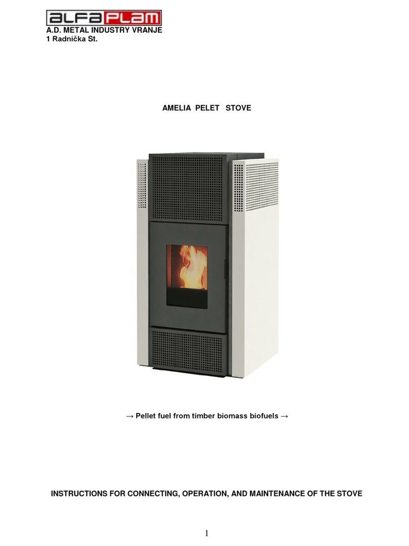
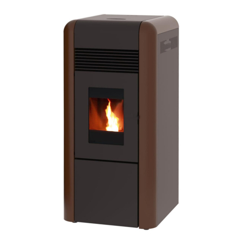
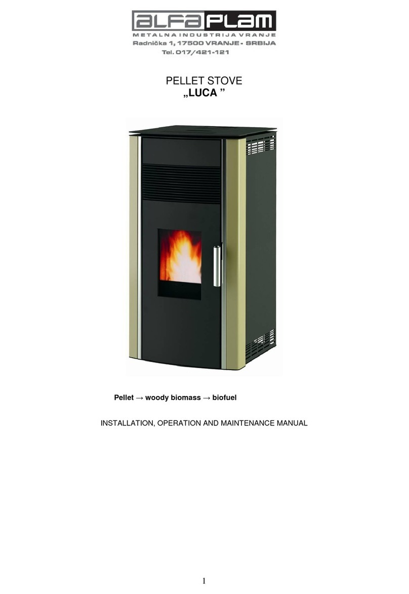
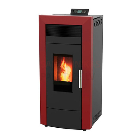
Alfa Plam GRANDE 37 User manual

1
A.D.METALNA INDUSTRIJA VRANJE
Radnička br: 1
PELLET BOILER
GRANDE 37
INSTRUCTIONS FOR USE, MAINTENANCE AND INSTALLATION
ENG.V.1.0_JUN 2018

DEAR CUSTOMERS !
Thank you for purchasing the GRANDE 37 Boiler.
Please read this user guide completely and carefully before you install and start using your GRANDE37 Pellet Boiler.
The heating units (hereinafter referred to as "pellet boilers" or "boilers") of Alfa Plam A.D. company have been designed,
manufactured and tested in accordance with the requirements of the applicable European Directives on safety standards.
These instructions are intended for end users, installers and technicians certified for operations on GRANDE 37 Pellet
Boilers. If you have any questions regarding the instructions or need an explanation, please directly contact the
manufacturer or an Alfa Plam authorized dealer.
Printing, translation or reproduction of the user guide, even partially, is only possible with the written permission of the Alfa
Plam company.
The boiler uses pellets as fuel. It operates automatically and uses a screw conveyor for dosing the pellets from the pellet
tank, which is part of the device placed above the boiler part of the plant. Fuel pellets are filled from above through the lid
to be used for that purpose. Make sure that the boiler is properly dimensioned with respect to the heating system and
energy requirements of the facility. Connection and commissioning of the unit should be done by a person authorized by
the Alfa Plam company.
The flame that develops in the boiler during normal combustion of wood biomass releases just the right amount of carbon
dioxide (CO2) that would be released by natural decomposition of the wood. The amount of CO2formed during combustion
or decomposition of the wood corresponds to the amount absorbed by the tree during its life cycle and turned into oxygen
and carbon. By the use of non-renewable energy sources (coal, fuel oil, gas), unlike those energy sources that are based
on wood, much larger amounts of CO2are released in the air. Carbon dioxide builds up during the years and contributes to
enhancing the greenhouse effect. The principle of clean combustion meets all the requirements of preserving the
environment, and the Alfa Plam company has directed all its development and its activities in the direction of fulfilling this
goal.

TABLE OF CONTENTS
1. THE PURPOSE OF THE USER GUIDE......................................................................................................1
2. RESPONSIBILITY OF THE MANUFACTURER ..........................................................................................1
2.1. REQUIRED GENERAL STANDARDS ....................................................................................................1
2.2. The following harmonized standards and/or technical specifications have been applied:...................1
2.3. TRANSPORT AND MOVEMENT OF PELLET BOILERS.......................................................................... 1
2.4. RESPONSIBILITY OF THE INSTALLER ............................................................................................... 2
3. INSTALLATION ..................................................................................................................................... 2
3.1. SETTING UP .....................................................................................................................................2
3.2. THE FLUE GAS EXHAUST SYSTEM.................................................................................................... 4
3.3. AIR SUPPLY ..................................................................................................................................... 6
3.4. CONNECTION TO THE POWER SUPPLY ............................................................................................. 6
4. NON-RETURN VALVE............................................................................................................................7
4.1. MIXING VALVE..................................................................................................................................7
5. BOILER FIRST STARTING ......................................................................................................................7
6. SAFETY WARNINGS..............................................................................................................................8
6.1. SAFETY WARNINGS FOR SERVICE PERSONNEL................................................................................8
6.2. SAFETY WARNINGS FOR USERS.......................................................................................................8
7. INSTRUCTIONS FOR BOILER SAFE STARTING AND SAFE CLEANING .....................................................9
7.1. ROUTINE MAINTENANCE AND CLEANING......................................................................................... 9
7.2. INSPECTION AND PARTS THAT NEED TO BE MAINTAINED............................................................... 10
7.3. ADDITIONAL MAINTENANCE .......................................................................................................... 10
8. IMPORTANT SAFETY INFORMATION................................................................................................... 10
9. PELLET QUALITY IS VERY IMPORTANT............................................................................................... 10
9.1. PELLET STORAGE........................................................................................................................... 11
10. BOILER CONTROL SYSTEM................................................................................................................. 11
10.1. Electrical connection diagram......................................................................................................... 12
10.2. Control panel (display) –keys and functions .................................................................................. 12
10.3. Menu ............................................................................................................................................. 14
10.3.1 Combustion Management Menu.......................................................................................................... 15
10.3.2 Heating Management Menu ................................................................................................................ 16
10.3.3 Chrono Menu ...................................................................................................................................... 17
10.3.4 Load Menu.......................................................................................................................................... 18
10.3.5 Time and Date Menu ........................................................................................................................... 18
10.3.6 Remote Control Menu ......................................................................................................................... 18
10.3.7 Language Selection Menu ................................................................................................................... 19
10.3.8 Keyboard Menu................................................................................................................................... 19
10.3.9 System Menu...................................................................................................................................... 19
10.4. Ignition of the boiler and working phases........................................................................................ 19
10.5. Possible problems and solutions .................................................................................................... 20
11. INFORMATION ON THE DISPOSAL AND STORAGE OF THE BOILER ...................................................... 22
12. TECHNICAL CHARACTERISTICS OF THE GRANDE 37 - PELLET BOILER................................................ 23
13. DIMENSIONS OF BOILER –GRANDE 37 .............................................................................................. 24
14. Scheme of hydraulic installation of pellet boiler –GRANDE 37 ............................................................ 25
1
1. THE PURPOSE OF THE USER GUIDE
The purpose of this User Guide is to invite the user to take all necessary safety precautions and provide all the necessary
actions that will guarantee proper and safe use of the heating appliance.
AMENDMENTS
This User Guide takes into account all the advanced technology that existed at the time of launching the pellet boilers on
the market.
It shall not apply to the products already on the market, accompanied by appropriate technical documentation, and
cannot be considered incomplete or inadequate after each change, adaptation or application of new technologies on
newer products.
The contents of this booklet should be carefully read and studied. Any information presented in this booklet should be
considered necessary for the proper installation, use and maintenance of your boiler.
Instructions should be carefully stored in a safe place. Instructions for use, maintenance and installation shall be
considered an integral part of the pellet boilers.
If the boiler is sold to a third owner, care should be taken to deliver this User Guide together with the boiler.
If the instructions happen to get lost, you can request a new copy from the manufacturer or an authorized dealer.
2. RESPONSIBILITY OF THE MANUFACTURER
By the delivery of this User Guide the Alfa Plam company a.d. disclaims any criminal or penal liability for direct or indirect
causing of:
-accidents and /or damage that occurred due to non-compliance with standards or notes contained in this User
Guide;
-accidents and /or damage that occurred due to improper or incorrect use by the user;
-accidents and /or damage due to modification or maintenance without authorization from the manufacturer Alfa
Plam a.d.;
-accidents and /or damage caused by the use of non-original or inappropriate spare parts.
Installing is the sole responsibility of the installer.
REQUIRED GENERAL STANDARDS
The GRANDE 37 product is manufactured in accordance with the following directives:
2006/42/EC Machinery Directive (MD)
2014/30/EU ElectroMagnetic Compatibility Directive (EMCD)
2014/35/EU Low Voltage Directive (LWD)
2011/65/EU Restriction of the use of certain hazardous substances Directive (RoHS Directive)
2009/125/EC Directive, Ecodesign
The following harmonized standards and/or technical specifications
have been applied:
-EN 303-5;
-EN 50581;
-EN 61000-6-2;
-EN 61000-6-3;
-EN 60335-1;
- EN 60335-2-102;
- EN 62233;
- Commission Regulation (EU) 2015/1189;
TRANSPORT AND MOVEMENT OF PELLET BOILERS
Take care of your own safety when moving the boiler.
Prior to transport and movement of the pellet boiler, which should be done with maximum safety precautions, make sure
that the load capacity of the cart is large enough to lift the boiler. Avoid sudden movements and/or improvised ways of
moving the boiler. Handling of the boiler in terms of lifting, shifting and moving from one place to another can be done by
the means of rod-shaped carriers threaded on one end. These rod-shaped carriers (4 pieces) are screwed on points
provided for that on either side of the boiler (Fig. 1). Four men are required for this operation. Boiler brackets are delivered
with the boiler!

2
Figure 1. Handling the boiler using the bracket
GATHER ALL PACKAGING MATERIAL AND KEEP IT AWAY FROM THE REACH OF CHILDREN. PARTS OF PACKAGING
MATERIAL (BAGS, FOILS, STYRENE) POSE A CHOKING HAZARD.
RESPONSIBILITY OF THE INSTALLER
The responsibility of the installer is to verify the correctness of installation, air supply and all the conditions that are
required for the installation of pellet boilers.
The responsibility of the installer is to verify compliance with legal regulations in the place where the boiler is installed.
The pellet boiler must be used in accordance with the instructions for use, maintenance and installation, and with respect
to the safety standards prescribed by the regulations in force at the place where the boiler is installed. Obligations of the
installer are defined by the UNI Standard 10683. Installers should check:
-the type of device to be installed,
-the convenience of the installation of the device, i.e. the minimum size of the space in which the pellet boiler is
intended to be installed,
-compliance with regulations concerning draining the flue gases, as identified in the instructions provided by the
manufacturer of the heating plants,
-the inner diameter of the chimney, the material from which it is made, whether it is straight and correct, and
whether it is free from clogging,
-height and possible vertical extension of the chimney,
-the existence and proper resistance of the chimney caps,
-the possibility of supply of the outside air,
-the possibility of concomitant use with other heat sources connected to the existing devices.
If the existence of the above indicated is established, the installation can begin. Follow with due attention the
manufacturer's instructions, the current safety norms and standards for fire protection.
After the first start of the boiler, it is necessary to carry out trial operation of the unit for at least 30 minutes, in order to
check whether all the required conditions are met.
Upon completion of the installation, the installer must submit the following documents to the buyer:
-operating, maintenance and installation instructions, supplied by the manufacturer (if not included as part of
the boiler),
-documents required by the applicable regulations,
-should teach the client how to use the device, how to carry out routine maintenance and cleaning.
3. INSTALLATION
Responsibility for the installation works at the place where the boiler is installed rests solely with the purchaser. Before
beginning the installation works, the installer should check whether all safety requirements are met, in particular:
-Check whether the regulations for the installation of pellet boilers meet local, national and European standards.
-Comply with all requirements stated in this document.
-Check that the pipes and lines for air supply correspond to the type of installation.
-Do not run a temporary electrical connection using inappropriate cables.
-Check grounding of electrical installations.
-Always use personal protective equipment and comply with all prescribed safety precautions.
-Always leave enough space for maintenance.
-Measure emission of flue gases after completion of the installation.
SETTING UP
It is advisable to remove packaging material of the pellet boiler exactly at the place where the boiler is to be installed.
Threaded
rods

3
If the adjacent walls and flooring are made of materials that are not heat-resistant, it is necessary to ensure adequate
protection and use of non-combustible insulation material.
To protect the flooring from combustible materials, it is mandatory to insert a metal plate that is 3 to 4 mm thick with the
front side at least 30 cm greater than the depth of the boiler, under the boiler. The pellet boiler must be installed in
accordance with the sketch, which defines the distance from the walls (Figure 2)
Figure 2. The minimum distance of the boiler from the walls
If the pellet boiler is installed in the boiler room where there are other devices that suck the air (other boilers, various
types of suction fans, etc.), make sure that the volume of air entering the premise is sufficient to guarantee safe
operation of the boiler.
If the chimney passes through the ceiling it must be sufficiently insulated with coating of non-flammable insulation
material.
After the pellet boiler is set in place, level it (bring it to a horizontal position) with adjustable legs.
The flue gas exhaust system MUST NOT BE CONNECTED TO:
-the uptake used by other heating devices (boilers, furnaces, fireplaces, etc.),
-the system for air extraction (from the hood, suction fan, etc.).
It is prohibited to install barriers for the regulation of the flow of flue gases!
The connector of the Ø80 mm flue pipe from the pellet boiler to the chimney should have the following characteristics:
-total length of up to 5 m (in the case of the connector of greater length connecting pipes diameter should be
increased to Ø130 mm),
-each elbow of 90˚ reduces the total length of the flue pipe by 1 m,
-cover intended for cleaning should be located on each elbow,
-pipe joints need to be sealed.
In case the resistance in the exhaust system is too high (numerous elbows, inappropriate terminations, bottlenecks
etc.), the flue gas exhaust is not guaranteed and it is necessary to increase the connecting pipes and elbows to greater
dimensions, i.e. to Ø130 mm. Also, when the chimney does not provide proper flue gas exhaust, it may cause
malfunction and consequently alarm activation in the GRANDE boiler. It is recommended that the chimney is inspected
by a professional person before installation of the GRANDE Boiler.
The system for discharging flue gases from the boiler functions at the underpressure generated in the combustion
chamber and the faint pressure in the Ø80 mm flue pipe. Therefore, care should be taken to provide complete tightness of
the flue pipe.
It is necessary to carefully analyze the position and condition of the area through which the chimney passes. If the flue
pipe passes through the wall and/or roof it should be suitably insulated in accordance with the safety regulations for fire
protection.

4
Make sure that the room in which the pellet boiler is installed has a sufficient amount of clean air, which guarantees
proper combustion. The air intake pipe should be of a minimum outer diameter of 110 mm and of a maximum length of
10 m. For every 90˚ elbow the maximum length is reduced by 1 m. If the length is too large, it is necessary to increase the
diameter of the air supply pipes.
If the grating is placed on the façade, the area of the air inlet port must be at least 100 cm2or larger.
The device works on 220-230 V, 50 Hz voltage. Make sure that the cables for electrical connection do not pass under the
boiler, that they are installed away from heated surfaces and that they do not come into contact with sharp objects that
may damage them. If the pellet boiler is under increased electrical voltage, the durability of electrical components will be
greatly reduced.
Do note remove the plug from the socket in order to switch off the boiler until the flame in the boiler is extinguished.
THE FLUE GAS EXHAUST SYSTEM
The flue gas exhaust system shall be in accordance with the applicable regulations. Do not connect the flue pipe of the
boiler to the chimney to which other furnaces are connected (Figure 3). The flue gas exhaust system must not end in a
closed and/or in semi-enclosed areas, such as garages, narrow passageways, hallways, sub-corridors and the like. After
connecting the boiler to the chimney, an authorized chimney sweep should check if there are any damages in the
connection and whether the connection is properly sealed. If the chimney is not suitable it must be executed in
accordance with the foregoing requirements (Section 3.1).
Figure 3
An uptake should be grounded in accordance with the applicable regulations. (Grounding is legally defined and
regulated.)
Grounding should be independent of the heating unit.
As far as dimensions and material are concerned, the flue pipe must meet the UNI 9615-9731, UNI 10683 –EN1856-1
standards.
Poorly preserved flue pipes or flue pipes made of inappropriate material (asbestos, galvanized sheet metal, porous
materials) do not comply with applicable regulations and adversely affect the operation of the boiler.
Flue gases can be discharged via the conventional chimney (see figure below) if the following requirements have been
met:
-Check if the chimney is maintained. For proper maintenance and/or restoration contact the chimney sweep.
-Flue gases can be discharged directly into the stack only if it is equipped with an inspection hole and if the
chimney is not larger than 20 X 20 cm, i.e. if the diameter is not larger than 20 cm.
-If the chimney is larger, appropriately insulated stainless steel tube (of a corresponding diameter) should be
inserted in it.
-Make sure that the chimney connection is properly sealed.
-Avoid contact with combustible material (ember) and in any case, install flame retardant insulation.
When fittings are used for connecting the pellet boiler to the chimney, elbows equipped with a cleaning hole shall always
be installed (Figure 4). Using the elbow with a cleaning hole enables routine cleaning without the need for dismantling the
pipe. Exhaust gases in the chimney connector are under slight pressure, thus it is necessary to make sure to check that
the cover for ash cleaning is completely hermetically sealed and that it is closed tightly after each cleaning. Make sure
that everything is properly put back in its place and check the condition of the seals.

5
Figure 4. Cleansing element
Pipes should be connected in such a way that their narrow connection element is always turned upward (Figure 4).
We recommend you do not make long horizontal sections of connection to the chimney. If there is no other possibility,
pipes should not have a slope downward, but upward to at least 5%. The horizontal part should not be longer than 2
meters.
Direct connection of the boiler to the chimney with a straight pipe greater than 1 meter in length is not recommended.
Figure 5. Figure 6
Maximum allowed length of 80 mm diameter flue gas pipe to its point of entering the chimney is 6 m. After that the diameter
of a flue gas pipe must be increased to 110 –120 mm. In that case, each elbow accounts for 1 m length. For example, if
there are three bends of 80 mm diameter, the length of the flue gas pipes of 80 mm diameter is thus changed by 3 m. Just
another 3 m of a straight pipe may be placed to the entrance of the chimney, in order to get 6 m length of the flue gas pipes
of 80 mm diameter. After that, the bend must be enlarged, led back to flue gas pipes or should enter the chimney of a
greater diameter, 110 –120 mm.
Care should be taken not to use bends of a sharp angle of 90º. They must be of a certain radius or made in segments.
Sharp angle bend increases resistance of the smoke flow through the bend.
- Each bend must be equipped with the cleaning door.
- Joints between the connection pipes must be tightened.
- For greater spacing, use 100 mm diameter connector. In that case, length of up to 8 m is allowed.
INSULATION AND DIAMETER OF ROOF OPENING
After you have determined the final position of the boiler, make an opening for the passage of the flue pipe. It depends on
the method of installation, pipe diameter and type of walls or roof through which the flue pipe is run. Insulation should be
done using mineral insulation material (glass wool) of nominal density greater than 80 kg/m3.
Ideal underpressure depends primarily on the lack of barrier contractions and/or angular connections. It is recommended
the elbows be at 30˚, 45˚ and 90˚. The 90˚elbows should be three-part elbows (Figure 7). In any case, it is necessary to
ensure that the length of the initial vertical part of the flue pipe is at least 1.5 meters. Proper exhaust of flue gases is
guaranteed in this way only.
Figure 7.

6
AIR SUPPLY
For proper combustion it is necessary to renew the air in the room with fresh air coming through an air opening in the
wall through the grate at door of the boiler room or through the open window. These solutions ensure proper combustion
and proper operation of the boiler.
The opening for air supply should be protected with the mesh against rain, wind and insects.
The opening should be located on the outer wall of the room where the pellet boiler is installed.
The UNI Standard 10683 prohibits bringing air from the warehouse for storing flammable materials or from the premises
where there is a risk of fire.
If there are other combustion devices in the room, it is necessary to ensure a sufficient amount of air for proper
combustion within all existing devices, as well as to take into account all the technical characteristics of all ventilation
systems built-in in the boiler room.
Figure 8.
CONNECTION TO THE POWER SUPPLY
The device must be connected to the electricity grid. Our boilers are equipped with an electrical cable for medium
temperature. If the power cord is damaged it must be replaced, so contact our authorized service. Before starting work on
the electrical connection, care should be taken about the following:
Make sure that the characteristics of electrical installations comply with data on the boiler.
The flue gas exhaust system should be grounded in accordance with local regulations. (Grounding is required by
law.)
The power cord must not in any case be exposed to the ambient temperature of over 80˚C. If you want to
connect the boiler directly to the power grid, it is necessary to install a two-pole switch, suitable for the mains
voltage in accordance with the applicable regulations, with contact spacing of at least 3 mm. The green-yellow
earth conductor must be disconnected in the switch. The double pole switch must remain accessible after
finishing the installation of the boiler.
Connecting to the power supply
The pellet boiler should be connected to the electricity grid. The electrical connection cable is 3 m long, white in colour
and marked "220 V". Another connection cable is black, intended for connection of the circulation pump and marked
"Pump".
Figure 9.
White –boiler supply (220 V)
Black –circulation pump

7
If the power cord is damaged, replace it. Replacement must be done only by an authorized person.
The power connector should remain available after the final installation of pellet boilers.
After installing the boiler the measurement of emission of flue gases is required.
4. NON-RETURN VALVE
Installation of a non-return valve in the hydraulic heating system is mandatory.
The function of the non - return valve is to prevent cooling of the water in the boiler and condensation in the boiler
and flue pipes. Condensation can occur as long as you do not spend 2 –3 fuel tanks.
Occurrence of condensation in the boiler is normal for the first ignition.
The non –return valve is installed at the outlet of the pump, behind the pump, instead in front of the pump. Care
must be taken about the direction of installation of the valve. Also, when purchasing, care must be taken of
whether the valves are placed on horizontal, on vertical line, or as inclined, because there are valves that are
installed only horizontally or only vertically, or that are universal.
Ensure that the non –return valve can be opened easily (try by finger), so that it can be opened by the pump power.
The non –return valve is placed behind each pump. If there are more pumps in the installation, then more non –
return valves are needed.
Connections to the boiler are 1". Non –return valves should also be 1", or larger.
If the non –return valve is not installed, the guarantee will not apply!
Diagram for installation of non –return valve:
1. Boiler Grande,
2. Circular pump,
3. Non - return valve
MIXING VALVE
- It is recommended that the hydraulic installation is fitted with a four –way mixing valve.
- For small installation a mixing valve is not required.
- For large installation a mixing valve is recommended.
- For underfloor heating installations a mixing valve is required. We recommend special thermostatic valves for underfloor
heating, which regulate the temperature of the water entering the floor of up to 50ºC. If there is no such a thermostatic
mixing valve, temperature of water entering the flooring system must be regulated in some other way. It is the job of the
designer and the installer.
- The mixing valve should be 1".
5. BOILER FIRST STARTING
The first starting of the boiler must be done only by an authorized person, otherwise the warranty becomes invalid.
INSTRUCTIONS FOR THE SAFETY OF PERSONS, ANIMALS OR PROPERTY
We want to draw attention of installers to some procedures to be followed so that proper installing of pellet boilers could
be guaranteed. It is necessary to comply with the required standards, but they themselves are not sufficient. For more
detailed information, it is necessary to read the rest of the instructions for use, maintenance and installation.
Connect the pellet boiler to the power grid.
Do not allow children or animals to approach the boiler.

8
Only use pellet of guaranteed quality and do not use other fuels.
Instruct all users of the possible risks and dangers and also inform them on how to manage pellet boilers.
If the boiler is placed on a wooden floor, it should be insulated in an appropriate manner.
The pellet boiler works in such a way that some underpressure is generated in the combustion chamber, so make sure
that the flue gas uptake is heat proof.
At first starting (at least 1 hour of operation of the boiler) smelly paint fumes are released, so it is necessary to ventilate
the room well.
6. SAFETY WARNINGS
SAFETY WARNINGS FOR SERVICE PERSONNEL
In addition to the general safety regulations, a person engaged in maintenance should respect the following:
Always use safety equipment and personal protection devices as determined by the Directive 89/391/EZ.
Make sure that the power supply is disconnected before beginning any activity.
Always use the proper tool.
Before beginning any intervention on the boiler, especially before coming into contact with the boiler make sure
that the boiler and ashes in it are cold.
THE PELLET BOILER IS CONSIDERED UNUSABLE EVEN IF ONLY ONE SAFETY DEVICE IS DEFECTIVE,
IMPROPERLY REPAIRED OR IF IT IS NOT WORKING.
Do not make any modifications for any reason, except with the permission of the manufacturer or an authorized
person.
Always use only the original spare parts. Do not wait for the boiler parts to be worn out before replacing them.
Replace the worn-out parts before they stop working completely, thus preventing the occurrence of damage due
to sudden failure of the part, which may seriously endanger the safety of persons and /or your property.
When cleaning the ashes, clean the firebox and the space beneath it.
SAFETY WARNINGS FOR USERS
The room in which a pellet boiler is or will be installed should be designed in accordance with local, national and
European standards.
The pellet boiler is a combustion device. During operation, some parts may heat up to very high temperatures.
The pellet boiler is a class C1 designed to burn wood pellets (pellets with a 6 mm diameter, maximum 30 mm in length
and of moisture content of up to 10%), i.e. C1 fuel (wood pellets) in accordance with the EN Standard 14961-2.
WHILE THE BOILER IS IN OPERATION, CHILDREN MUST NOT APPROACH IT OR PLAY WITH IT!
During operation of the boiler, it is recommended to follow the precautions listed below:
During operation of the boiler DO NOT approach or touch the door of the combustion chamber. There is a RISK
OF BURNS.
During operation of the boiler DO NOT approach or touch the flue pipe. There is a RISK OF BURNS.
During operation of the boiler DO NOT perform any cleaning on the heating installation..
During operation of the boiler DO NOT open the door of the firebox because it works properly only if the door is
hermetically sealed.
During operation of the boiler DO NOT clean the ashes.
DO NOT allow children or animals to approach the pellet boilers.
FOLLOW THE INSTRUCTIONS PROVIDED IN THIS DOCUMENT.
For the correct use of the boiler also follow the following advice:
Only use the fuel recommended by the manufacturer of the boiler.
Follow the instructions for maintenance.
Clean the firebox after consumption of pellets in the pellet tank (3 to 14 days, only while the boiler and ashes in it
are cold).
DO NOT use a pellet boiler in case of system failure or other irregularities, unusual noises and/or if you suspect
a malfunction. IMMEDIATELY contact an authorized service center.
DO NOT pour water on the boiler and extinguish fire in the combustion chamber with water.
DO NOT lean on the boiler because it may not be sufficiently stable and can be overturned.
DO NOT use the pellet boiler as support or as a means of supporting other objects. Do not leave the lid of the
pellet tank open.
During operation, DO NOT touch the painted parts of the boiler.
DO NOT use wood or coal in the pellet boiler, only use pellet of the following characteristics:
size: diameter: 6 mm
max. length: 30 mm
moisture content: up to 10%

9
firewood value: 16.9 MJ/kg, that is 4.7 kWh/kg
ash content: below 0.7%
DO NOT use the boiler for burning waste.
Always make sure you provide maximum safety.
7. INSTRUCTIONS FOR BOILER SAFE STARTING AND SAFE
CLEANING
For starting the pellet boiler DO NOT in any case use heating oil, kerosene or similar derivatives and other flammable
liquids. While the boiler is in operation, keep these liquids and other liquids away from it.
Make sure that the pellet boiler is properly installed and that it is not moving.
Make sure that the firebox is tightly closed and will remain closed during boiler operation.
It is necessary to provide access points for measuring the emission and they must be self locking and tight sealed.
Remove ashes only when the pellet boiler is cold.
Do not use abrasive cleaners for cleaning pellet boilers.
ROUTINE MAINTENANCE AND CLEANING
Using a vacuum cleaner to vacuum ashes facilitates the work of removing ashes from the boiler.
Before beginning any maintenance or a cleaning procedure, follow the following safety rules:
Turn the pellet boiler off before beginning any procedure.
Make sure that the boiler is cold before beginning any procedure on the boiler.
Vacuum the ashes deposited in the combustion chamber at least once every ten days, i.e. after consumption of pellets in
the pellet tank (only while the boiler is cold) (Figure 11).
Once a month, open the front bottom door of the heat exchanger on the right side of the boiler and vacuum the interior
(Figure 11).
Always check if the boiler and ashes in it are cold.
The holes on the burner must be clean.
Figure 10 Figure 11
This is a firebox for burning pellets (Figure 10). We recommend you inspect and remove the ashes from the bottom of the
combustion chamber at every cleaning. This is the only way you can ensure that the boiler will work properly.
For any further information, contact the installer. The manufacturer does not have direct control over the work of
installers and cannot guarantee for any work done or for maintenance works.
The manufacturer does not in any case assume responsibility for damage caused by third parties.
Make sure that the pellet boiler and ashes in it are cold.

10
Following the consumption of the entire tank of pellets the combustion chamber must be cleaned by vacuuming and/or
removing all debris generated by pellet burning.
Incompletely burned pellets should never be returned to the pellet tank or disposed of in the container for ashes.
INSPECTION AND PARTS THAT NEED TO BE MAINTAINED
CHECK THE ITEMS LISTED BELOW TO ENSURE PROPER OPERATION OF PELLET BOILERS. THESE PRECAUTIONS
ENSURE THE MAXIMUM OUTPUT OF THE BOILER AND THE TEMPERATURE OF THE SYSTEM:
Make sure that the pellet boiler and ashes in it are cold.
For a complete cleaning every week or after 200 kg of pellets have been consumed (whichever is earlier) the
ashes underneath the firebox and from the combustion chamber must be vacuumed. You can use a brush to
clean the walls of the firebox.
GENERAL CLEANING OF THE BOILER AT THE END OR BEGINNING OF THE HEATING PERIOD:
Make sure that the boiler and ashes in it are cold. Turn off the power supply to the boiler.
Upon completion of the heating period, disconnect the power supply to the boiler. It is very important to clean
and inspect the boiler as described in this manual.
The door seal may get detached after some time, although it is attached with glue resistant to high temperature.
To reattach the seal apply an adhesive resistant to high temperature on the back side of the seal. In this way the
sealing of the firebox door is guaranteed.
CONNECTION OF THE FLUE PIPE TO THE CHIMNEY (should be cleaned at the end of each heating season).
Make sure that the pellet boiler and ashes in it are cold.
- The flue pipe, chimney and chimney cap should be inspected and cleaned annually. To carry out the
procedure professionally, you should contact the chimney sweep.
ADDITIONAL MAINTENANCE
Your pellet boiler is a source of heat in which only pellet may be used. Annual maintenance of the boiler can only be
performed by a person authorized by the Alfa Plam company a.d.
Regular annual service will preserve proper operation of the heating units, ensure their greater efficiency, keep the
warranty valid and extend the life of the machine itself.
It is recommended to carry out the procedures described in the previous section at the end of the heating period. The
purpose is to verify and ensure proper operation of all components.
8. IMPORTANT SAFETY INFORMATION
You have purchased the highest quality product.
The supplier is at your service for any information you may need. Proper installation of the boiler, carried out in
accordance with the attached guidelines, is important for the prevention of any defect, risk or danger of fire.
The pellet boiler works on the basis of underpressure generated in the combustion chamber, therefore it should always
be ensured that the joints to the chimney are sealed and tight.
In the event the chimney catches fire, people and animals should immediately leave the residential area. Disconnect the
power supply to the main switch immediately after that, or cut the plug out of the socket (only if you are not putting
yourself at risk), and contact the fire department.
For safety purposes and preservation of function of the pellet boiler, do not use finely chopped wood.
Do not use the pellet boiler for incineration.
9. PELLET QUALITY IS VERY IMPORTANT
The quality of pellets is very important!
The boiler is designed to use pellets. Considering that a variety of types and sizes of pellets are available on the market, it
is important to choose pellet that contains no impurity, which is compact and does not generate dust.

11
Consult the supplier on the type of pellet, which needs to be 30 mm in size and have a 6 mm cross-section. Proper
operation of the boiler depends on the type and quality of the pellets. The manufacturer is not in any way responsible for
poor performance of the boiler due to the use of poor quality pellets.
PELLET STORAGE
Pellets should be stored in a dry room that is not too cold. Cold and wet pellet (temperature about 5˚C) reduces the
thermal power and demands increased boiler cleaning.
People with an impaired spine and pregnant women should avoid lifting a bag of pellets.
The manufacturer waives all responsibility for any damage or improper operation of the boiler due to the use of low
quality pellets.
Pellets should be in accordance with the DIN Standard 51731, DIN plus, Ӧ-Norm -7135 or other comparable European
standards.
PELLETS SHOULD NOT BE KEPT NEAR THE BOILER. Leave a distance of at least half a meter.
When handling pellets, make sure that they are not wasted.
If you add sawdust in the pellet tank, it may block the system for dosing pellets.
10. BOILER CONTROL SYSTEM
The boiler is equipped with advanced control system which provides a safe, efficient and reliable management of the
operation and maximum functional efficiency of the boiler.
Characteristics:
easy to install and use,
easy and direct user functions,
reliable and flexible functional software specifically developed for pellet boilers,
advanced features available to installers in order to adapt different configurations and installations.

12
Electrical connection diagram
Control panel (display) –keys and functions
Keys:
Key
Function
Description
P2
On/Off
To ignite or extinguish boiler press and hold the key for 3 s after
the acoustic sound
Unblock
To Unblock the system when in Block Mode, press and hold the
key for 3 s and longer after the acoustic sound.
P4
P6
Change values
Change values and settings in menus and submenus
Browse menus and sub - menus
Browse menus and submenus
Visualization
Manage the visualization menu
P1
Esc
Exit menu or submenu
P3
Menu
Enter menu or submenu
Modify
Manage change in menu
Set
Save settings in menu
Reset system maintenance 2
Function
Timer reset (only if this option is active)

13
P5
Manual Standby
Press and hold key for 3s to activate Standby mode
LED symbols:
Igniter
Led ON: Igniter is active
Auger
Led ON: Auger is active
Pump
Led ON: Pump is active
L3
Aux 1
Led ON: Aux 1 is active
L4
Additional motor
Led ON: Additional motor is active
L5
Aux 2
Led ON: Aux 2 is active
L6
Aux 3
Led ON: Aux 3 is active
L7
Not active
L8
Not active
L9
Pellet level sensor
Led ON: Out of pellet
Exterior thermostat
Led ON: Contact is open
Sanitary water switch
Led ON: Sanitary water required
Display:
- Display:
oDate and Time
oChrono Modality (D-Daily, W-Weekly, We-Week-End)
oSystem Power (P1, P2, P3, P4 and P5)
oRecipe (Pellet 1)
oSystem Mode (Check Up, Ignition, Stabilization, Run Mode, Modulation, Standby, Safety, Extinguishing, Recover
Ignition, Block, Off)
- Errors (Alarms):
If error (alarm) occurs, system switches to Block Mode.
Error Code
(Alarm Code)
Error (Alarm) Description
Er01
Safety Thermostat Activated
Er02
Safety Manometer Activated
Er03
Extinguishing due to low temperature of flue gases
Er04
Extinguishing due to high water temperature in the boiler
Er05
Extinguishing due to high temperature of flue gases
Er06
Safety thermostat on auger housing is activated
Er07
Encoder error. No signal
Er08
Encoder error. Unable to adjust number of revolutions
Er09
Low water pressure
Er10
High water pressure
Er11
Error due to problems with the internal clock
Er12
Extinguishing due to ignition failure
Er15
Power outage longer than 50 minutes
Chrono Enable
Summer-Winter
Set System Power
Recipe
Leds
Current water
temperature in the boiler
Set water temperature in
the boiler
Error Code (Alarm)
Maximum number of
operating hours achieved
Date and Time
System Mode

14
Er16
Communication error RS485
Er17
Airflow regulator error
Er18
No pellet
Er25
Cleaning motor error
Er39
Airflow regulator broken
Er41
Minimum airflow in CHECK UP phase not reached
Er42
Maximum airflow reached
Er47
Auger encoder signal error
Er48
Unable to adjust the number of revolutions of auger motor
Er52
Module error I/O I2C
Other messages:
Sond
This message during Check-Up phase indicates that the temperature on one or
more probes equals the minimum value (0°C) or maximum value (depending on the
type of probe). Check that the probe is not open (0°C) or in short circuit (maximum
value on temperature scale).
Service
This message indicates that the planned number of working hours has been
reached and it is necessary to call the service.
Clean
This message indicates that the planned number of working hours has been
reached and it is necessary to clean the boiler.
Block Ignition
This message appears if the system shuts down while in Ignition phase. The
system will stop only when it switches to Run Mode.
Link Error
This message informs there is no communication between LCD display and the
controller in the boiler.
Standby Man
Appears if the system is in Standby Mode due to pressed P5 key
- Visualizations:
By pressing keys P4 and P6 you enter the Visualization Menu. In this menu some values of system parameters can be
seen.
L3 On P1 Pump
LED number and state of pump out
L4 Off Safety Valve
LED number and state of out Aux 1
L5 Off Out not used
LED number and state of additional motor out
L6 On Load Engine
LED number and state of out Aux 2
L7 Off Out not used
LED number and state of out Aux 3
Exhaust T.:103
Temperature of flue gases (°C)
Water T.: 55
Water temperature (°C)
Buffer T.: 52
*Buffer temperature (°C)
Room T.: 21
*Room temperature (°C)
Pressure: 1548
*Water pressure in the boiler (mbar)
Air Flux: 680
The flow rate of primary air (cm/s)
Speed Fan: 1000
Flue gases fan speed/voltage (rpm/V)
Auger ON: 800
Auger motor speed/voltage (rpm/V)
Product Code 448-0000
System Code
FSYD01000135.0.2
Controller firmvera version
PSYSF01000209.0.2
Display firmvera version
*In case the boiler configuration has no installed probes these values are not visible.
Menu
The Menu consists of the User Menu and the Technical Menu.
The Technical Menu includes settings and adjustments which allow the manufacturer to modify parameters and system
configuration. The Technical Menu is not available to user but only to the authorized representative of the manufacturer.
User Menu
By pressing P3 key User Menu opens.

15
By pressing P4 and P6 keys choose the desired menu or sub - menu. Use P3 key to open the desired menu or sub -
menu.
To increase or decrease parameter value press P4 or P6 keys. To save the new set parameter value press P3 key. To
cancel all modifications and return to previous values press P1 key.
After change of parameter value the new value is transferred to main controller.
If the transfer was not successful, the following message appears on the display:
In this case, it is necessary to repeat the action.
The User Manu consists of multiple menus and sub - menus.
By pressing P3 key the User Menu opens and the following list of sub - menus is visible:
Menu
Description
Combustion Management
The menu for the modification of combustion power,
auger motor calibration and flue gases motor.
Heating Management
The menu for the modification of set value for water
temperature in the boiler, buffer and other heating
parameters.
Chrono
The menu for the Chrono program modalities and
ignition/extinguishing times.
Manual Load
The menu for the manual auger loading. Possible only if
the system is in OFF state.
Time and Date
The menu for setting the time and date.
Remote Control
The menu for activation of the remote control.
Language
The menu for change of the control panel language.
Keyboard Menu
The menu for setting the contrast and the light of LCD
panel.
System Menu
The menu to access the technical adjustments.
Combusti on Man agement Menu
This Menu provides modification of parameters determining combustion power. It consists of four sub - menus.
By pressing P3 key the Menu opens and following sub –menus are visible:
Combustion Power
This Menu provides combustion power management of the system in Manual or Automatic Mode (if option is available).
In Manual Mode user can manage combustion power by himself.
Combustion
Description
1-5 (Combustion Power 1, 2, 3, 4 and 5)
Power is set manually by choosing Power 1, 2, 3, 4 or 5.
Auto (option not active)
Power is set automatically by the system
Parameter Name
Maximum Value
Current Value
Minimum Value

16
By pressing P3 key Combustion Power Menu opens.
By pressing P4 and P6 keys choose the desired combustion power. To save the new set parameter value press P3 key.
To cancel all modifications and return to previous values press P1 key.
Combustion recipe
This Menu provides combustion recipe management. In case there is only one recipe set as default this menu is not
available.
Auger Calibration
This is the Menu for managing the feed rate of the auger. The system has 10 calibration steps (from -5 to +5; set default
value is 0). The effect of calibration is valid in the operating mode and in modulation. For each step, the value is
increased or decreased by 5%.
Example: Calibration value = -2; (-2*5%= -10%) This means that the calibration value of the auger speed will be
decreased by 10% in relation to default value.
Default values
C03=600
C04=900
C05=1200
C06=1600
C07=2000
C11=600
Calibrated values
C03=540
C04=810
C05=1080
C06=1440
C07=1800
C11=540
Combustion Fan Calibration
This is the Menu for managing the number or revolutions of the combustion fan. The system has 10 calibration steps
(from -5 to +5; set default value is 0). The effect of calibration is valid in the operating mode and in modulation. For each
step, the value is increased or decreased by 5%.
Example: Calibration value = -3; (-3*5%= -15%) This means that the calibration value of the auger speed will be
decreased by 15% in relation to default value.
Default values
U03=1000
U04=1200
U05=1400
U06=1600
U07=1800
U11=900
Calibrated values
U03=1150
U04=1380
U05=1610
U06=1840
U07=2070
U11=1030
Note: Do not calibrate the auger and the flue gases motor without previously consulting an authorized service
representative or the manufacturer.
Heating Manageme nt Menu
This is the Menu for modification of parameters which determine the heating performance of the boiler. It consists of five
sub - menus. By pressing P3 key the Menu opens and following sub –menus are visible:
Boiler Thermostat
This is the Menu which allows management of set water temperature in the boiler. The water temperature in the boiler can
be set between 30°C and 80°C. By setting the desired water temperature in the boiler the user conditions the boiler to
operate on set power until the water temperature in the boiler reaches the set value. When the set water temperature in the
boiler is reached, the boiler switches to Modulation Mode and continues to operate on minimum power.
Buffer Thermostat
This Menu allows the modification of buffer temperature. This Manu is active only if buffer is installed.
Combustion Power
Maximum power - Power 5
Current set power–Power 1
Minimum power –Power 1

17
Room Thermostat
This Menu provides the modification of set room temperature. This Menu is visible only if the ambient probe or room
thermostat options are activated.
Summer –Winter
This Menu provides the modification of the boiler functionality depending on the season. The screen displays one of two
symbols: or .
Heating Power
This Menu is not active.
Remote Keyboard
This Menu allows management by Remote Keyboard. First it must be activated by previous setting of certain parameter.
Chrono Menu
This is the Menu for setting the time of system start up/shut down and programming stove operation for specific time
periods.
Contains two sub - menus:
- Modality
- Chrono program
Modality
By opening the Chrono Menu two sub –menus are visible Modality and Programming.
By pressing P4 and P6 keys choose one of sub –menus and open it by pressing P3 key. The Modality Menu contains the
following list:
The description of settings in the Modality Menu:
Description
Keys
Display
Current modality blinks
Entering change mode
P3
Select the desired modality
P4 and P6
Cancelation of change and
return to previous modality
P1
Save changes
P3
Exit the Menu
P1
Chrono program
By opening the Chrono Menu two sub –menus are visible: Modality and Programming.
By pressing P4 and P6 keys choose one of sub –menus and open it by pressing P3 key. The Chrono Program Menu
contains the following list:
The description of settings in the Chrono Program Menu:
Program selection
Keys
Display
Current program blinks
Entering sub - menu
P3
Select the desired program
P4 and P6
Exit the Menu
P1
Table of contents
Other Alfa Plam Pellet Stove manuals
Popular Pellet Stove manuals by other brands

England's Stove Works
England's Stove Works 25?PAH Installation & operation manual

Kozi
Kozi BayWin owner's manual

Harman
Harman XXV Freestanding Pellet Stove Installation & operation manual

Hudson River
Hudson River DAVENPORT owner's manual

United States Stove
United States Stove American Harvest 6039 owner's manual

Thelin
Thelin GNOME PELLET STOVE owner's manual

Lopi
Lopi Leyden manual

Osburn
Osburn HYBRID-45 MF owner's manual

Piazzetta
Piazzetta P963 THERMO Instructions for installation, use and maintenance

Harman Stove Company
Harman Stove Company PC 45 Installation and operating manual

Breckwell
Breckwell Tradition P24FS owner's manual

CS THERMOS
CS THERMOS INSERTO SKYLINE instruction manual