Alfa Plam LUCA 12 Specification sheet

A.D. METALNA INDUSTRIJA VRANJE
Radnička br: 1
PELLET STOVE
„LUCA 12”
INSTRUCTIONS FOR USE AND MAINTENANCE OF LUCA 12
ENG_v.1.0

Contents
Introduction 1
Product serial no. 1
Materials 1
Certification 1
Dimensional features: 2
Technical features of the product 3
Fuel properties 4
Safety recommendations 4
General Recommendations 5
Safety devices 5
Surrounding area for using the product 6
Installation 6
Positioning the appliance 6
Stovepipe properties 7
Smoke exhaust to the outer wall 8
Draining smoke to the roof through a traditional funnel 8
Dismantling and waste disposal 9
Electrical connections 9
Room temperature gauge 9
Using the Product 9
The necessary checks and controls for the first ignition 10
Loading the fuel 10
Control System of the Furnace 10
Electrical connection scheme 10
The control panel (display): use and features 11
K100 display 11
Alarms 12
Other messages 12
Visualizations 12
User menu 1 13
Chrono 13
User Menu 2 15
Turning the furnace on and the state function 15
Check Up 15
Ignition 15
Stabilization 16
Normal –Run Mode 16
Modulation 16
Safety 16
Extinguishing 16
OFF 16
Block 16
Ignition Recovery 16
Other functions 16
Management of the absence of power 16
Management of pellet loading calibration 16
Management of flue gas engine correction 17
Safety thermostat 17

Periodic cleaning of the furnace 17
Shutting down during the ignition phase 17
Possible problems and solutions (Troubleshooting) 17
MAINTENANCE OF THE FURNACE 19
Routine maintenance 19
CLEANING THE DISPLAY AND PARTS OF EXTERNAL INSULATION 19
CLEANING THE CERAMIC GLASS 19
ROUTINE MAINTENANCE, TYPE 1 ACTIVITY 20
Special maintenance 23
SPECIAL MAINTENANCE TYPE 2 ACTIVITIES 23
SPECIAL TYPE 3 MAINTENANCE ACTIVITY 23
CHECK THE SEALS 24
CLEANING THE EXHAUST DUCT 25
Putting the furnace out of use 25

1
Introduction
Firstly, we would like to take this opportunity to thank you for purchasing this ALFA PLAM product.
We have prepared this short user guide for you in order to make the use of our products much easier.
Special technical problems referred to herein should be inspected by the persons involved in the installation, assembly
and commissioning of the product to ensure that operations are carried out as accurately as possible.
This booklet about assembly, use and maintenance must be read carefully before assembly and use of the product. It
should be considered an integral part of the product and must be kept in a safe place.
Procedures for assembly, connecting, inspections, maintenance and repairs must be carried out by qualified personnel.
It is recommended that the first ignition or, rather, commissioning, is performed by qualified personnel.
Do not use any flammable liquids for the ignition process.
This product should not be used by persons with reduced physical, sensory and mental abilities or lack of experience and
skills (including children), unless they are supervised and given instructions by someone who can guarantee their safety.
Children must always be supervised by an adult in order to protect them from accidental contact with hot surfaces of the
furnace, and to prevent them from using or touching the furnace settings.
Please call your dealer in order to obtain additional information that you need which is not included in this user guide.
The following symbols are used in this user guide:
⚠ATTENTION: Safety warning
PROHIBITED: Prohibited action
INFORMATION: Important information.
Alfa Plam bears no responsibility or liability for any direct or indirect personal injury or property damage arising from
non-compliance with the indications given and highlighted in this user guide.
Product serial no.
Product serial number can be found on the label affixed to the back of the appliance as well as on the cover of this user
guide.
Product serial number will be required every time the user requests auxiliary services.
Materials
ALFA PLAM products often use materials that have the following properties:
•Very thick sheets that provide a solid structure of the appliance;
•For specific models the company uses very thick majolica and cast iron materials to give the product a unique design
and elegant finish;
Before they are painted at high temperature, metal parts are exposed to the phosphate treatment to bring the painting
process to the best level and to improve the end product;
Seals which provide hermetic sealing of the combustion chamber must be checked periodically to prevent the improper
burning, which can occur due to excessive wear of seals;
Glass and ceramic elements for the combustion chamber door. For more details regarding cleaning procedures, see the
section on maintenance.
Certification
This product respects the EN 14785 standard on wood pellet heating appliances in residential areas. Also abide by the
laws implemented by the following European directives:
-2004/108/EC (Electromagnetic Compatibility Directive);
-2006/95/EC (Low Voltage Directive);
- 89/106/EEC (Construction Products Directive);

2
Dimensional features:

3
Technical features of the product
Product: LUCA 12
Unit of measure
Maximum
Minimum
Thermal power
kW
12.9
2.7
Heating power
kW
11.8
2.6
CO emission (per 13% of oxygen)
%
0.015
0.030
Efficiency
%
91
95.1
Nominal electrical power
W
420
Nominal voltage
V
230
Nominal frequency
Hz
50
Fuel
Wood pellet
Fuel consumption per hour
kg/h
2.7
.5
The flow of gas masses
g/s
9.0
3.3
Combustion gas temperature
°C
128
57
Minimum withdrawal pressure
Pa
12.0
12.0
Tank capacity
kg
14
Autonomy
h
5.2
28
Energy required for operation
W
90
Discharge of flue gases
mm
∅80
Combustion air intake
mm
∅50
Net weight
kg
156
Heating volume*
m³
337
* The values are calculated in accordance to law 10/91 for households with a thermal requirements of 35 W/m³
and a height of 3 m.

4
Fuel properties
The furnace is first characterized by the fact that it burns natural fuel (wood pellets), which is environmentally derived
from the wood industry waste (chips/sawdust). Once shavings and sawdust are properly cleaned and dried, which arise in
the wood processing procedures, they are compressed under extremely high pressure to produce small cylinders of pure
wood: pellets. Each tiny cylinder may vary in length and width from 1 to 3 cm in length and from 6 to 8 mm in radius.
Wood pellets are primarily characterized by low humidity (below 12%) and high density (= 600 kg/m3), as well as their
uniformity and compactness, providing this type of fuel with high calorific value features (DTV 41005000 kcal/kg).
Wood pellets which are used as fuel for this furnace must have excellent quality characteristics, such as, for example,
those defined by the following standards: DIN 51731, ÖNORM M 7135 and EN plus A1, with basic numeric items listed below
⚠ATTENTION: As is required by the relevant European laws governing the characteristics of commercial fuels, pellets
must be manufactured exclusively using shavings of unprocessed wood without added matter.
s is strictly prohibited.
⚠ATTENTION: In order to bring furnace operation to the highest level, the use of wood pellets certified by an accredited
body is recommended. Using other types of pellets compared to those specified by the manufacturer can lead to failure of
the furnace and may void the warranty.
Quality standards for
wood pellets
Unit of measure
ÖNORM M 7135
DIN 51731
DIN plus
EN plus A1
Diameter
mm
from 4 to 10
from 4 to 10
from 4 do 10
6 ± 1
Length
mm
5 x P1
< 50
5 x P1
3,75<D<40 3
Density
Kg/dm3
> 1.12
1.0 –1.4
> 1.12
>0.6 (average)
mass volume)*
Humidity
%
< 10
< 12
< 10
< 10
Ash
%
< 0.50
< 1.50
< 0.50
< 0.50
Thermal power
kWh/kg
> 5
4.86 –5.42
> 5
> 4.5
Sulfur
%
< 0.04
< 0.08
< 0.04
< 0.05
Nitrogen
%
< 0.3
< 0.3
< 0.3
< 0.3
Chlorine
%
< 0.02
< 0.03
< 0.02
< 0.02
Dust
% weight
< 2.3
-
< 2.3
< 1
Binders
% pressed
mass
< 2
2
< 2
1A maximum of 20% of pellets may have a length 7.5 times larger than the diameter D
2DIN prohibits the use of any added substances. However, this prohibition does not apply to small heating systems.
3Up to 5% of pellets may have a length greater than 40 mm, and a maximum of 45 mm.
⚠ATTENTION: If the appliance is not used for a sufficiently long period of time (more than two weeks), all remaining
pellets should be removed from the tank to prevent it from becoming too wet as this can lead to failure of the product.
Storage and handling of wood pellets are important tasks which must be done carefully.
- Fuel must be stored in a dry and warm place.
- Pellets must be handled as to prevent too many crushed pellets that become fine powder.
Compliance with these two simple rules will allow better combustion efficiency and will even help maintain proper
operation of moving mechanical parts of the appliance.
Safety recommendations
⚠ATTENTION: Carefully read the attached user guide with the instructions before installing.
⚠ATTENTION: The firebox must be empty before the appliance is turned on in case
of any difficulty when turning the device on.
It is strictly prohibited to use any other type of solid or liquid fuel except wood pellets with a radius of 6 mm for which
the furnace is designed. Avoid using wet or crushed pellets.
In order to bring furnace operation to the highest level, the use of wood pellets certified by an accredited body is
recommended. Using other types of pellets compared to those specified by the manufacturer can lead to failure of the
furnace and may void the warranty.

5
When putting the pellets into the furnace make sure they don’t fall into other internal parts of the product expect into
the proper container.
⚠ATTENTION: If you can’t turn the furnace on you will have to empty the combustion chamber. Not following this
procedure may cause excessively strong burning that can lead to creating significant amounts of smoke.
⚠ATTENTION: Do not open the door or turn off the electrical cable during the ignition phase or during shutting down,
or while the furnace is running, even if the combustion chamber is blocked or overloaded; start the process of turning it off
and wait for the furnace to complete operating phases before solving the problem. Do not attempt to turn on the furnace
again until the problem is solved.
⚠ATTENTION: Do not disturb the shutdown procedure of the furnace (for example, by
turning off the power cord) until it is completed.
⚠ATTENTION: If the wood pellets accumulate in the combustion chamber when the appliance is operation, immediately
turn off the appliance and turn it on again using the greater ventilation program. If the pellets continue to accumulate, try
using other types of wood pellets or call the helpline.
⚠ATTENTION: Never manually put the pellets into the combustion chamber.
⚠ATTENTION: In order to prevent possible accidents, always follow the instructions for proper use contained in this user
guide for the appliance and its electrical components.
⚠ATTENTION: Installation procedures, connecting inspections, maintenance and repairs may be carried out by qualified
personnel.
⚠ATTENTION: The product must be installed in full respect of the applicable legal standards.
⚠ATTENTION: Always follow the safety recommendations and standards indicated by this user guide.
⚠ATTENTION: Anyone who performs interventions on the product must first read and fully understand the contents of
this user guide and fully know the dashboard of the product.
⚠ATTENTION: The product can be used, modified, or programmed by adults only. Incorrect or arbitrary settings can lead
to dangerous situations and faults.
⚠ATTENTION: ALFA PLAM bears no civil or criminal liability for damages in the event that the product is subjected to
unauthorized repairs or replacement of parts.
⚠ATTENTION: While in the product is running some of its surfaces can reach extremely high temperatures.
That’s why it is recommended to the user to take all the necessary precautions, particularly when children or elderly or
disabled people are present.
⚠ATTENTION: Do not block or clogs the hot air drain in any way. Do not cover the product with cloth or other similar
materials.
⚠ATTENTION: In order to avoid accidental tipping over of the appliance, never lean or place too much weight on the open
door during the cleaning process.
It is recommended to avoid these kinds of pressures and to take all the necessary precautions, particularly when children
or elderly or disabled people are present.
General Recommendations
⚠ATTENTION: Never use the product for purposes other than those for which it is designed and manufactured.
⚠ATTENTION: The product must not be used for cooking.
⚠ATTENTION: The product should not be used in the event of any fault or failure. In these cases, immediately turn off
the power cord of the product from the wall socket.
NEVER leave the door open while the product is running.
Stovepipes must be checked regularly.
NEVER use steam to clean the product.
Always consult qualified and authorized personnel for any service interventions that may be necessary. Use only original
spare parts for replacement of broken parts.
Fuel can only be loaded into the burner through automated loading, and not directly by the user.
⚠ATTENTION: In case of "unsuccessful ignition”, all pellets deposited in the combustion chamber must be removed
before one tries to re-ignite the furnace. Pellets that are removed from the combustion chamber should never be returned to
the tank.
This user guide must be considered an integral part of the product and must be used during its entire service life. It must
be stored in a safe place. In case the user guide is lost or damaged, a replacement copy can be obtained from the dealer.
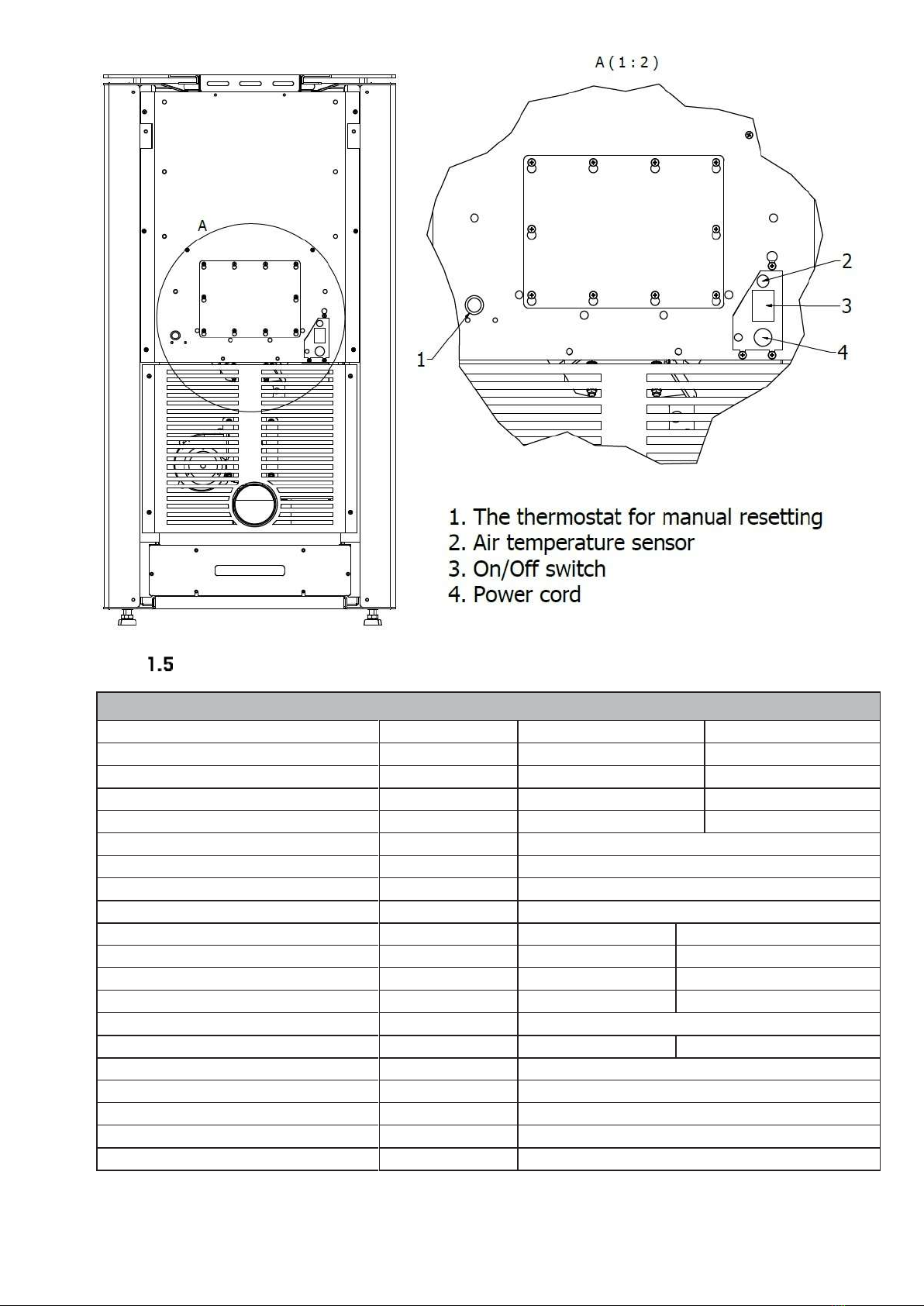
Safety devices
The product is equipped with the following safety devices:
•A thermostat for determining the temperature of the tank: this device shuts down operation of the product each time
it exceeds the set safety limit;
•Meter for determining the smoke temperature: this element determines the smoke temperature and continually
monitors the proper functioning of the product;
•Pressure switch: this element determines whether there is a clogging in the pipe;
•Thermometer for the environment: this element constantly monitors the temperature of the room where the furnace
is located;
•Operation modulation mode: if the flue gas temperature exceeds the set safety threshold, the appliance will
automatically reduce the amount of pellets for burning until the temperature drops below the set limit.

6
Incorrect parameter settings can lead to exceeding of the safety limits and can lead to excessive consumption of pellets.
The safety limits can also be exceeded due to poor ventilation of the room in which the furnace is located, which does not
provide the appliance with enough cold air.
Disabling the safety devices is PROHIBITED. When the user eliminates the cause of activation of the security system,
the appliance can be restarted in order to restore its proper functioning.
⚠ATTENTION: The appliance must be installed in such a way so that its electrical cable is easily accessible.
specified in chapter 3. ALFA PLAM bears no responsibility for any personal injury or property damage that may occur if the
furnace is not used in accordance with the conditions listed in this user guide. ALFA PLAM also bears no responsibility for
any personal injury or property damage that may occur if the user fails to comply with the following regulations:
A) All the necessary measures and precautions must be taken to ensure that no party turns on the equipment while
carrying out repairs, adjustments, replacement of parts and maintenance operations;
B) Do not remove or modify any safety devices on the appliance;
C)The appliance must be connected to the system for smoke removal which is functioning properly;
D)Make sure that the surrounding area in which the furnace is set is sufficiently ventilated, as prescribed in this user
guide.
Surrounding area for using the product
⚠ATTENTION: The appliance must be installed in a surrounding area with ventilation, and it must be provided with
sufficient air combustion in accordance with the applicable regulations. This is important for ensuring its proper operation.
⚠ATTENTION: The room must have a volume not less than 20 m3and must possess all the necessary ventilation
conditions, as described in Chapter 2 of this user guide. These conditions will provide the necessary air flow to allow for
proper combustion (40 m3/h).
Using the product in the bedrooms and bathrooms is PROHIBITED.
Using the product in spaces with another heating appliance which does not have its own system for air intake is
PROHIBITED.
Placing the product close to flammable materials is PROHIBITED.
Placing the product on the floor made of flammable material unless a protective plate is used made of non-flammable
materials is PROHIBITED.
Using the product in explosive and potentially explosive atmospheres is PROHIBITED.
Installation
You must comply with all local and national laws and European standards when installing, using and maintaining the
appliance.
Positioning the appliance
Our product creates heat by bringing the necessary air in for the combustion process directly from the environment which
needs to be warmed up.
For this reason and because of the basic safety of the users of the furnace, the appliance should always be installed
inside an adequately aired out area to ensure a constant flow of combustion air.
Therefore, it is necessary to place the air intake vents that are connected to the air outside (as shown in Figure 2.1)
In accordance with the provisions set forth in the UNI 10683 standard, air intake vents must have the following
characteristics:
1. They must not have an internal cross-section of less than 80 cm2;
2. They must be placed at an approximate height of the floor;
3. They must be adequately protected by wire mesh or grate so that the minimum radius condition for air flow is not
diminished;
4. They must be placed so as not to be blocked in any way.
Correct flow of fresh air can also be ensured by using the opening to the next room, if that room comes equipped with
direct ventilation and does not pose a risk of fire, such as a warehouse, garage or storage, as set forth by the UNI10683
standard.
It is recommended that you avoid placing a heating device in the rooms with devices which cannot work in a closed
manner compared to the surrounding area or in the rooms where there are devices which can reduce the pressure in the
room itself compared to the external environment, as this can lead to problems with low air intake for our product (UNI
10683).
⚠ATTENTION: It is forbidden to discharge combustion products of the furnace in a common stovepipe.
When checking the system compatibility, it is recommended to determine if the support surface of the support (floor)
possesses adequate load capacity (kg) to support the weight of the product. If this is not the case, it is recommended to take
appropriate safety measures (for example, use a distribution board).
When installing the furnace, it is advised to place it at the appropriate distance from the wall to allow access to the back
side of the furnace (we recommend at least 20 cm) and to the side (we recommend 80 cm). Such a space may be necessary,
for example, in order to be able to adequately clean the product.

7
Figure 2.1: Example of the necessary vents
Never allow flammable materials to come close or, indeed, come into contact with the outer surfaces of the combustion
chamber as it can reach extremely high temperatures when the product is running.
If the floor is made of flammable material (e.g. hardwood), it is recommended to protect it by placing a layer of non-
flammable material under and around the furnace.
More information on the minimum safe distance from flammable materials (see figure 2.2.a):
- Minimum distance from combustible floor (H = 4 cm);
- Minimum distance from combustible rear wall (B = 50 cm);
- Minimum distance from combustible side wall S = 40 cm);
- Minimum distance from combustible material on the front side (Fr = 150 cm).
Once you've determined where you will place the furnace, it is possible to adjust the furnace feet in order to achieve the
correct height. Tilting the furnace to the side requires two people. After you adjust the feet, carefully lower the furnace (see
Figure 2.2.b).
Figure 2.2: Distance when setting up
Stovepipe properties
The main properties of the stovepipe are listed below, based on the requirements of the standard:
-The inspection valve (I);
-Maximum height of the pipe which is connected directly to the smoke drain on the furnace should be between 2 to 3
m;
A
A

8
-If you need a horizontal segment, it should not exceed 1.5 m in length and a slope of 3 to 5% in order to help drain the
smoke;
Use the back part which is resistant to wind and water in order to prevent change of state of a slightly higher pressure in
the stovepipe (do not put a horizontal part at the end of the stovepipe);
The state of a slightly higher pressure in the stovepipe is needed to facilitate the flow of smoke from the combustion
chamber.
Keep in mind that any removal of excess heat is done by the electric control part (modulation, shutting down, etc.)
-The exhaust duct must be made of materials that are resistant to combustion products and moisture (a review will
enable the removal of any moisture);
-Ducts must be manufactured in a way as to prevent any leakage of smoke.
-The duct must be isolated, especially the outer part, which is exposed to atmospheric conditions.
using fully horizontal segments
Figure 2.3: Exhaust duct
The room in which the heating device will be assembled should not have hoods because they can reduce the pressure
of the surrounding area.
It is strictly prohibited to close the air vents.
The exhaust duct should be cleaned at least once a year; we recommend that you perform a thorough cleaning of the
exhaust duct and its connections.
ignition after a period of inactivity.
⚠ATTENTION: The exhaust duct must be built in accordance with the provisions of the standard.
⚠ATTENTION: Check if the chimney has a minimum pulling power of 10 Pa using the appropriate tools.
Smoke exhaust to the outer wall
One of the solutions that can be applied includes storing the furnace that uses wood pellets near the outer wall of the
house so that the exhaust fumes are directly released outside (Figure 2.4). Some of the notes set forth by the standard for
this type of system configurations are listed below:
-Always make sure that there is an inspection valve (I) in order to enable regular cleaning procedures, as well as the
removal of moisture which can be formed;
-The end of the funnel (T) must be such that it is resistant to wind and water;
-Make sure that the stovepipe is properly insulated in the part that passes through the wall.
If the stovepipe for draining the exhaust gases is completely outside, it must be made of a double stainless steel wall to
provide greater resistance to atmospheric conditions, as well as proper temperature of the exhaust gases themselves.
Draining smoke to the roof through a traditional funnel
Furnace exhaust fumes can be removed through a traditional funnel that is already built-in (Figure 2.5), if it meets the
applicable Standards and features the main characteristics of a good funnel (C), which are briefly listed below:
-Proper insulation, first in the outer part which is exposed to the atmospheric conditions;
-The constant inner radius (there cannot be segments with a smaller radius);
-It must be made of a material which is resistant to high temperatures, to the effects of the combustion products and
to the corrosive effects of moisture which may be formed;
-A mostly vertical position without deviating from the vertical angles greater than 45 °.
It is recommended that the base of the funnel is equipped with a chamber for collecting solid matter and moisture (R).
The chamber must be accessible through a hermetic door (I).

9
Figure 2.4: Draining smoke to the outer wall of the chimney Figure 2.5: Draining smoke to the roof through a traditional
chimney
It is recommended that you follow the guidelines set forth in the standards in relation to the size and radius of the chimney
(C). In any case, never use an exhaust duct with an inner radius smaller than 100 mm.
In the case of the exhaust ducts of greater radius, there must be a steel pipe (A) within the funnel bricks or mortar (C), as
shown in Figure 2.6.
The steel pipe must be insulated using a suitable heat-resistant material, such as rock wool or vermiculite (B), and it
must be separated from the outer part of the funnel.
Figure 2.6: An example of connection to the chimney
In case of fire in the chimney or stovepipe, immediately turn off the furnace and disconnect it from the electrical system.
Dismantling and waste disposal
The packaging consists of materials which are not toxic or harmful. No special conditions are needed for its disposal.
The user is responsible for the disposal of the remaining components of the packaging. The user must follow the proper
disposal procedures in accordance with the applicable standards in the country where the product is assembled.
⚠ATTENTION: The packaging elements must be kept out of reach of children who are not supervised or out of reach of
persons with disabilities.
Electrical connections
The product can be connected to the mains only after the electrical insulation is assembled.
Connect the product to your household power.
Just press the main switch on the back of the appliance if you want to turn it on. When you do this the furnace will be
ready for ignition. For ignition procedures and programming, refer to section 4.
Room temperature gauge
Room temperature gauge can be adjusted only after setting up the electrical installation.
This gauge allows the temperature in the room where the furnace is placed to be continuously monitored.
Placing the room temperature gauge in a suitable spot will ensure proper operation of the product.
Using the Product

10
The necessary checks and controls for the first ignition
The following guidelines must be followed when first igniting the product:
•Make sure all safety requirements have been met (see section 1.8);
•Connect the appliance to the power supply only when you are sure that the voltage power supply is 230 V 50 Hz.
When you’ve made sure of this turn the switch on the back panel to "ON” - switched on;
•Make sure that the display on the control panel is turned on, which indicates that the appliance is properly plugged
into the power supply;
•Make sure there is enough fuel in the tank for the planned period of operation.
The fuel must be in accordance with the instructions given in the relevant section of this guide.
Painted parts of the furnace can emit smelly fumes during the first few ignitions. This phenomenon is associated with
a chemical process of stabilization of used paint. For this reason, during this period the room where the furnace is located
must be regularly and properly ventilated.
Loading the fuel
Open the upper door of the product to insert the pellets. You must comply with regulations with regard to the fuel
contained in the relevant part of this user guide.
⚠ATTENTION: Do not let the bag with wooden pellets come into contact with hot parts of the product while you load the
fuel.
⚠ATTENTION: Do not remove the protective grid inside the part for loading the pellets.
⚠ATTENTION: Do not lean the full weight of the bag containing the fuel to the product.
⚠ATTENTION: Close the upper door when you have finished loading the pellets.
Periodically check the amount of wood pellets contained in the tank and fill it up in time.
⚠ATTENTION: Excessive moisture can crush the pellets into fine powder, which can lead to increased sedimentation in
the boiler area, and even block the insertion/loading system (auger).
When inserting the pellets make sure that the pellets do not accidentally fall into the other inner parts of the appliance
except into the appropriate tank.
Only use pellets with a diameter of 6 to 8 mm.
Figure 3.1. Inserting the pellets
Control System of the Furnace
The furnace has an installed advanced control system which provides a safe, efficient and reliable controlling of the
operation and a maximum functional use of the furnace.
It is characterized by:
ease of setting up and using
easy and direct user features,
reliable and flexible functional software specifically designed for pellet furnaces,
advanced features available for installers in order to adapt different configurations and installations
Electrical connection scheme

11
The control panel (display): use and features
K100 display
The main frame shows:
time and date, chrono
activation, combustion
energy, heat energy,
functional state, current
room temperature, set
room temperature, LEDs
Display
Meaning
Main Temp.
The current value of the room temperature
State
Functional state of the furnace
Main Therm.
Set room temperature
Comb. Power
Combustion power
Heat Power
Heating power
Time
Time
Chrono
Scheduled operation
Push
button
Feature
P1
Exit menu/submenu
Flue gas engine
Power
cable
Switch
Flue gas
engine
…sensor
Igniter
Pressure switch: cables
connected to the
positions 1 and 2, and
the silicon hose to the
P1 connector

12
P2
Turning on and off (hold down for 3 seconds), reset errors (hold down for 3 seconds), chrono activation
and deactivation
P3
Enter the user menu 1/submenu, enter the user menu 2 (hold down for 3 seconds), saving data
P4
Enter the visualization menu, maximizing
P5
Enter the visualization menu, minimizing
Led
Feature
Led
Feature
Lack of pellets
Preset room temperature reached
The direction of air flow
Remote thermostat temperature
reached (if connected to the remote
thermostat)
Alarms
Description
System state
Code
Safety error - safety thermostat: signals when the system is off
Block
Er01
Safety error - pressure switch: signals only if the combustion fan is turned
on
Block
Er02
Shutdown in case of flue gas temperatures lower than permissible
Block
Er03
Shutdown in case of flue gas temperatures exceeding the permissible
temperatures
Block
Er05
The pellet thermostat is activated
Block
Er06
Encoder fan error: no encoder signal
Block
Er07
Encoder fan error: failed combustion fan regulation
Block
Er08
Date and time are not correct due to a prolonged power outage
Block
Er011
Ignition failed
Block
Er012
Power outage
Block
Er15
Communication error - display disconnected
Block
Er16
Air flux regulator error
Block
Er17
No more pellets
Block
Er18
Faulty air flux sensor
Block
Er39
The minimum air flux is not reached during the testing phase
Block
Er41
Maximum airflow reached (F40)
Block
Er42
Error: door open
Block
Er44
Auger encoder error: no encoder signal
Block
Er47
Auger encoder error: auger speed control failed
Block
Er48
Module error I/O 12C
Block
Er52
Service error. This informs that the planned period of operation has been
reached (after preload): the system will stop when it goes into operation mode.
Block
Service
Other messages
Description
Code
Probe error when controlling during the testing phase
Prob
This informs that the planned period of operation has been reached. It is necessary to clean the
furnace or boiler.
Clean
Door open
Door
The message appears if the system is turned off during ignition (after preload) by the external
device: the system will stop when it goes into operation mode.
Block ignition
No communication between the motherboard and the display (keypad).
Link Error
Periodic cleaning is in progress.
Cleaning On
Visualizations
Pressing P4 and P5 opens the visualization menu.
Here you can see the value of the ambient temperature, flue gases, engine speed of flue gases, ON auger time*, etc, at all
times. The following indicators of the furnace operation can be checked in the visualization menu:
Display
Description
Exhaust T. [ºC] 103
Flue gas temperature
Room T. [ºC] 25
Local room temperature
Rem. Room T. [ºC] 25
Remote room temperature; visible only if the remote thermostat is active
Air Flux
750
Air flux; visible if the primary air flux gauge is active
Fan Speed [rpm] 1250
The exhaust gas fan speed;
Auger [ºC] 1.2
ON auger time;
Cleaning [h] 450
Work time left before cleaning the furnace; visible only if the timer is active
Work time [h] 2985
Total furnace work time in the work mode, modulations and security
Ignitions [h] 106
Number of ignition attempts
Product Code: 494- 0000
Product code

13
User menu 1
Short press P3 to activate user menu 1.
Keys P4 and P5 list different submenus (combustion management, heating management ...); pressing the P3 key opens
any selected submenu.
Combustion Management
Power
In this submenu it is possible to modify the power of the combustion system. Keys P4
and P5 select between the 5 powers ( Power 1, Power 2, Power 3, Power 4 and Power 5).
When you select the desired power press the P3 key to confirm. Exit the submenu by
pressing P1.
Auger Calibration
Allows modification of the set value for the duration of the ON auger time. The values
range from -7 to 7. The default value is 0 (see Section 4.6.2)
Fan Calibration
Allows modification of the set value for the speed of the flue gas engine. The values
range from -7 to 7. The default value is 0 (see Section 4.6.3)
Heating Management
Room Thermostat
This menu allows modification of the set temperature value in the local room (the room
where the furnace is assembled). The temperature value set up in this menu is a
requirement for furnace operation. Namely, the furnace will work in the selected mode until
it reaches the preset value of the room temperature. When the preset value is reached then
the furnace goes into a modulation state or it works using minimum power. The furnace
exits the modulation state and returns to the mode of normal operation as soon as the room
temperature falls below the preset value. The temperature value is set up using the P4 and
P5 keys and then the set value is confirmed by pressing P3. Exit the submenu by pressing
P1.
Remote Room Thermostat
This menu allows you to modify the value of the thermostat in a distant room. It is visible
only if the external thermostat is installed, while a heating plant that uses it is set up to use
an external thermostat.
Remote Control
This menu allows turning the remote control options on and off.
Chrono
Chrono program
It is used for scheduling operation of the furnace and for turning the furnace on and off
in certain time periods.
Manual Load
This procedure activates the manual loading of pellets with the activation of the preset
modality of the auger engine. Loading stops automatically after 600 seconds. The system
must be turned off in order for the function to be activated.
Cleaning Reset
Menu for resetting the "System Maintenance 2” function. Visible only if the option
“System Maintenance 2” is active.
Chrono
In order to adjust the programmed operation of the furnace it is necessary to access the Chrono menu.
The Chrono menu is accessed in the following manner:
-Short press P3 to activate user menu 1.
-Press P4 and P5 to list the submenus until you reach the Crono submenu.
-Press P3 once again and enter the Chrono submenu
-The following is shown on the display:
Chrono
Modality
Chrono program Program
Modality
Chrono program
Press P4 and P5 to select the Modality or Chrono program and then press P3 to enter one of the two submenus.
4.3.1.1 Modality
Allows selection of desired modality or disables all set programs.
Programming is enabled or disabled by pressing P2
Use P4 and P5 to select the desired way of programming the Daily,
Weekly and Weekend furnace operation.
Pressing P3 confirms the selected way of programming furnace
operation.
Save your settings by pressing P1.
Disabled
Daily Weekly
Week End
4.3.1.2 Chrono Program
Chrono program provides three types of programming: daily, weekly and weekend programming.
The following is shown on the display in the Chrono Program:

14
Chrono
Modalit
y
Chrono
program
Pprogram
Daily
Weekly
Week-end
The system provides three types of programming: daily, weekly and weekend programming. Selection is made by pressing
P4 and P5 after which the user enters the selected program by pressing P3.
1. Daily Programming
The following is shown on the display once the Daily submenu or the daily program is entered:
Days of the week are selected by pressing P4 and P5. When you select the date press P3.
Setting the activation and deactivation time of the program for the selected day is done as follows:
Enter the change of time (the preset time is blinking) by pressing P3.
Change the time by pressing P4 or P5.
Save by pressing P3.
Activate ("●”appears) or deactivate the time period ("○”remains) by pressing P2.
Example: For example, select Monday and press P3. Then press P3 and ON time (time of turning on of the furnace) starts
blinking. By pressing P4 and P5 you can set up the desired ON time and confirm it by pressing P3. In this way ON time can be
set up to, for example, 9:30 AM. When ON time is set up press P5 and then the OFF time (time of turning off of the furnace)
starts blinking. By pressing P4 and P5 you can set up the desired OFF time and confirm it by pressing P3. In this way OFF
time can be set up to, for example, 11:15 AM. In the end press P2 in order to activate the program. The following is shown on
the display:
Daily
Monday
ON
OFF
●09:30 -
11:1
5
○00:00 -
00:0
0
○00:00 -
00:0
0
This program schedules the furnace to turn on on Monday at 9:30 AM and turn off at 11:15 AM.
Save your settings by pressing P1.
For daily programming it is possible to switch the program from the previous day to the next day.
The procedure is as follows:
Select the day of the week for programming and setting up the turn on and turn off time.
Set the clock to ON on the previous day at the desired time: e.g., 8:30 PM.
Set the clock to OFF on the previous day at 11:59 PM.
Set the clock to ON on the next day at 12:00 AM.
Set the clock to OFF on the next day at the desired time: e.g., 6:30 AM.
The system will turn on at 8:30 AM on Tuesday and will turn off at 6:30 AM on Wednesday.
2. Weekly Programming
In terms of weekly programming, programs are the same for all days of the week.
The following is shown on the display once the Weekly submenu or the weekly
program is entered.
The programs are activated and deactivated in the same way as with the daily
programming.
3. Weekend Programming
In terms of weekend programming it is possible to choose between programs:
-Mon-Fri
-Sat-Sun
Selected programs will be active from Monday to Friday or Saturday and
Sunday.
The programs are activated and deactivated in the same way as with the daily
programming.
Weekly
Mon-Sun
ON
OFF
○00:00
00:00
○00:00 -
00:00
○00:00 -
00:00
Week-end
Mon-Fri
ON
OFF

15
○00:00
00:00
○00:00 -
00:00
○00:00 -
00:00
User Menu 2
Long press P3 (3 seconds) to activate user menu 2.
Keys P4 and P5 list different submenus ((Keyboard Settings, Keyboard Menu ...); pressing P3 opens any selected
submenu.
Keyboard Settings
Time and Date
Used for setting up the day, month, year and current time.
Language
Menu for changing the language
Keyboard Menu
Learn Menu
Allows manual updating of the menu; access is protected by a four-digit password
and the procedure cannot be stopped once it is started. In the event of a failed save or
change of the menu, this procedure starts automatically.
Set Contrast
Menu used to regulate the contrast of the LCD screen.
Set Minimum Light
Menu used to regulate the brightness of the LCD screen when controls are not used.
Keyboard Address
This menu is password protected and is not available to the user.
Node List
This menu displays the following: table communication address, table typology,
firmware code and firmware version. Data cannot be changed. Table typology that can be
displayed are as follows:
MSTR Master INP KEYB OUT
CMPS composite SENS Sensor COM Communication
Acoustic Alarm
Allows enabling or disabling of the keyboard alarm.
System menu
Menu for entering the technical menu. This menu is password protected and is not
available to the user.
Turning the furnace on and the state function
The furnace is turned on by long pressing P2 for 3 seconds. After that come the next function states of the furnace:
Check Up
During the check up phase the initial checks of the input signals or the probity of safety probes and pressure switches of
the furnace are done. In this phase the flue gas engine runs at maximum speed while the auger and igniter are turned off. The
check up phase lasts for a few seconds, and a successful check up is followed by the ignition phase.
Ignition
The ignition phase consists of four sub phases which alternate, and those are:
- Preheating phase
- Pellet preload phase
- Fixed ignition phase
- Variable ignition phase
The message IGNITION is displayed during the entire ignition phase. There are no special markings on the display for sub
phases.
4.5.2.1 Ignition Preheating
At this stage there is warming of the igniter before dispensing of the pellets starts. In order for pellet burning to be as
efficient as possible, it is desirable that the igniter is already preheated at the time when dispensing the pellets starts. At this
stage the igniter is active and the auger is inactive. Flue gas engine runs on lower rpm in order to promote heating of the
igniter.
4.5.2.2 Ignition Preload
In this phase there is the initial dispensing of pellets or the auger loads a certain amount of pellets necessary for ignition.
In this phase the igniter, auger and flue gas engine are active.
4.5.2.3 Ignition –Fixed Phase
This phase is a fixed time period that lasts for 180 seconds and in case that the furnace ignition requirement is reached
before the expiry of this phase it will always last until the end and only after the expiration of the fixed time period will the
furnace move into stabilization phase. In this phase the igniter, auger and flue gas engine are active.
4.5.2.4 Ignition –Variable Phase

16
This phase occurs after the fixed ignition phase. The duration of this phase is a variable period that lasts until the moment
of fulfillment of the ignition requirements or until the moment when the flue gas temperature of 50 °C is reached. In case the
furnace ignition requirement is met before the expiry of the duration of this phase, it is stopped and the next phase follows,
which is the stabilization phase. In this phase the igniter, auger and flue gas engine are active.
Stabilization
The stabilization phase is a transitional phase between the ignition phase and the run mode phase. This phase occurs
when the ignition requirement is met, that is, when flue gas temperature reaches 50 °C. It lasts for three minutes and during
that time the auger, flue gas engine and the igniter are active.
Normal –Run Mode
The normal run mode begins following the stabilization phase. In this phase there are five levels of power that can be set
up as explained in the user menu 1. In this phase the igniter is turned off while the auger, flue gas engine and area engine are
active and run with different intensity depending on the level of power of the furnace. The furnace runs on the given power
until the modulation requirements are met.
Modulation
The furnace goes into the modulation phase when one of the two conditions are met:
1. When the furnace reaches the preset ambient temperature
2. When the flue gas temperature reaches a value greater than 250 °C
In the modulation phase the furnace runs on minimal power - power 1, until the moment when the temperature decreases
below the threshold value.
Safety
The Safety status occurs when flue gas temperature exceeds 275 °C. In this phase dispensing the pellets stops until the
temperature of flue gases decreases. If there is no decrease in temperature in the next 60 seconds the furnace goes into an
alarm stage and displays the Er05 message.
Extinguishing
The furnace is turned off by long pressing P2 for more than 3 seconds. The extinguishing phase occurs next during which
dispensing of pellets stops and the flue gas engine and the ambient fan operate at maximum capacity in order for the furnace
to cool down as soon as possible. Minimum duration of the extinguishing phase is 30 seconds and the requirement for the
furnace to completely turn off is for the flue gas temperature to be less than 68 °C.
OFF
During this phase the furnace is turned off, that is, no furnace output (flue gas engine, ambient fan, igniter and auger) is
active.
Block
The block state occurs in the event of a fault or alarm. In the block state the exhaust gas fan, auger and igniter are turned
off. To exit press P2 for 3 seconds: if there is no more block and no cause for alarm the system will turn off.
Ignition Recovery
The furnace goes into this phase in two cases:
1. If there is a power failure in the operating mode and the flue gas temperature is greater than 50 °C.
2. By pressing the main switch at a time while the furnace is in the extinguishing phase.
Other functions
Management of the absence of power
In the absence of power, the system keeps the most important functional data. When the power is restored the system
evaluates the saved data and:
If the furnace is turned on and the temperature of exhaust. gases is greater than 50°C, the system enters
the recovery point. Pressing P1 can lead to a sudden new system ignition.
If the furnace is turned on but the temperature of exhaust. gases is lower than 50°C, the system enters
the shutdown point with error Er15.
If the furnace is turned off or in extinguish or block phase, the system returns to its previous state.
In the absence of power for more than a week the system goes into block with an error message Er11
indicating that the DATE/TIME values are incorrect. When P1 is enabled the TIME value starts to blink signaling the
need for updating the TIME and DATE with the CLOCK function.
Management of pellet loading calibration
The user has the option to calibrate the dispensing of pellets in the user menu 1. Calibration ranges between -7 ÷ 7. 1=5%.
Each calibration of dispensing the pellets is applied to all workforce in percentages. For example, if -1 is set up then the
dispensing of pellets will be reduced by 5% in all operating modes (Power 1 - 5).

17
Example
Before
calibration
Power 1 =
2.0
Power 2 =
3.0
Power 3 =
4.0
Power 4 =
5.0
Power 5 =
6.0
Step = -1
Power 1 =
1.9
Power 2 =
2.85
Power 3 =
3.8
Power 4 =
4.75
Power 5 =
5.7
Never calibrate dispensing of pellets without consulting with the service center first.
Management of flue gas engine correction
The user has the option to calibrate the rpm of the flue gas engine in the user menu 1. Calibration ranges between -7 ÷ 7.
1=5%. Each calibration is applied to all workforce in percentages. For example, if it is set up to 3 then the rpm of the flue gas
engine will be increased by 15% (3x5%) in all operating modes (Power 1 - 5).
Example
Before
calibration
Power 1 =
1000
Power 2 =
1200
Power 3 =
1400
Power 4 =
1600
Power 5 =
1800
Step = +3
Power 1 =
1150
Power 2 =
1380
Power 3 =
1610
Power 4 =
1840
Power 4 =
2070
Never calibrate the rpm of the flue gas engine without consulting with the service center first.
Safety thermostat
In the event that the temperature in the pellet tank reaches the value higher than 90 °C, the safety thermostat activates in
order to prevent the ignition of pellets in the tank. The system goes into block mode and there is an alarm message Er01.
Periodic cleaning of the furnace
When the system is stable after a specified time interval (every 45 minutes), the system automatically performs periodic
cleaning which lasts for 30 seconds.
During the periodic cleaning, the flue gas engine works with increased intensity while dispensing of pellets stops.
Shutting down during the ignition phase
When the system shuts down during the ignition phase (after the preheating phase) through an external device or an
internal chrono device, the system goes into shutdown mode when it enters running mode at the end of ignition phase.
Message Block ignition is shown on the display.
If an error occurs, the system immediately goes into shutdown; if P2 is pressed, it is possible to immediately introduce
the system into the turning on or off.
Possible problems and solutions (Troubleshooting)
Message on
the display
Description
Possible causes
Resetting errors
Possible solution of alarm
causes
Er01
Activation of the
safety thermostat
High temperature
inside the furnace
Wait until the
furnace has cooled
and then unscrew
the plastic cap on
the thermostat and
press the reset
button
Check the heat sink and
check that there is no obstacle
for the hot air to get out
Too high a
temperature in the room
where the furnace is
assembled
Contact the service center
Faulty thermostat
Er02
Activation of the
safety pressure switch
Obstruction of flue gas
drain
Press and the
P2 key for more than
3 seconds
Check contamination of
flue pipes and funnel
Incorrect funnel
installation
Contact the service center
Faulty pressure switch
Er03
Shutting down due
to very low flue gas
temperatures
Poor combustion (too
few or too many pellets
remain in the combustion
chamber)
Wait for the
furnace to shut
down and then
press P2 for more
than 3 seconds
Check the size of the pellet
granules
Check for contamination
of the furnace chamber
Empty pellet tank
Check the status of flue
pipes
Faulty flue gas probe
Contact the service center
Er05
Shutting down due
to very high flue gas
temperatures
The temperature of
flue gases exceeds the
limit
Wait for the
furnace to shut
down and then
press P2 for more
than 3 seconds
Insufficient heat transfer -
contact the service center
Obstruction of flue gas
drain
Check contamination of
the flue drain and funnel
Faulty flue gas probe
Er07
Encoder error
Wait for the
furnace to shut
Contact the service center
Table of contents
Other Alfa Plam Pellet Stove manuals