4
Connexion mécanique
Branchement électrique
Механическое подключение
Электрическое подключение
Mechanical connection
Electric installation
Mechanischer Anschluss
Stromanschluss
• L’installation de la centrale ne peut être
effectuée que par du personnel qualifié et
expérimenté.
• La centrale doit être installée solidement et
fermement afin de garantir une utilisation sûre.
• La centrale est connectée au système de
conduits d’air.
• Il est nécessaire de garantir une distance
de sécurité avec la turbine du ventilateur en
marche (pour cela de accessoires spécifiques
sont utilisés ou on opte pour la longueur du
conduit d’air nécessaire).
• Ne pas raccorder de coudes près des piquages
de raccordement du caisson. La distance
minimale du conduit d’air droit entre le
caisson et la première branche des conduits
d’air doit être de 1xD dans le conduit d’aspiration
et de 3xD dans le conduit d’extraction
de l’air, où D est le diamètre du conduit
d’air.
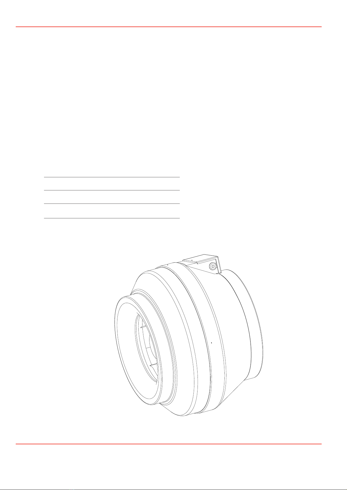
Le ventilateur peut être monté dans n’importe
quelle position (Fig. #1.6).
• En raccordant les conduits d’air, faire attention
à la direction du flux d’air indiqué sur le caisson
de la centrale.
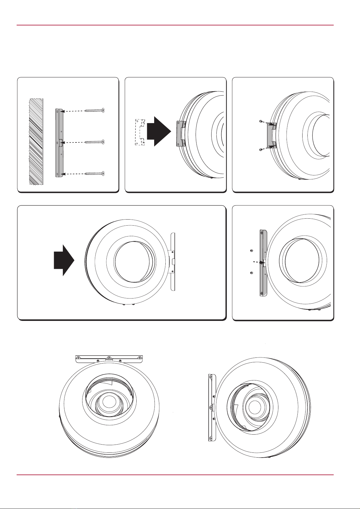
• Pour l’installation des ventilateurs sur un mur
ou au plafond, nous recommandons d’utiliser
des accessoires spécifiques : les supports
(Fig. #1).
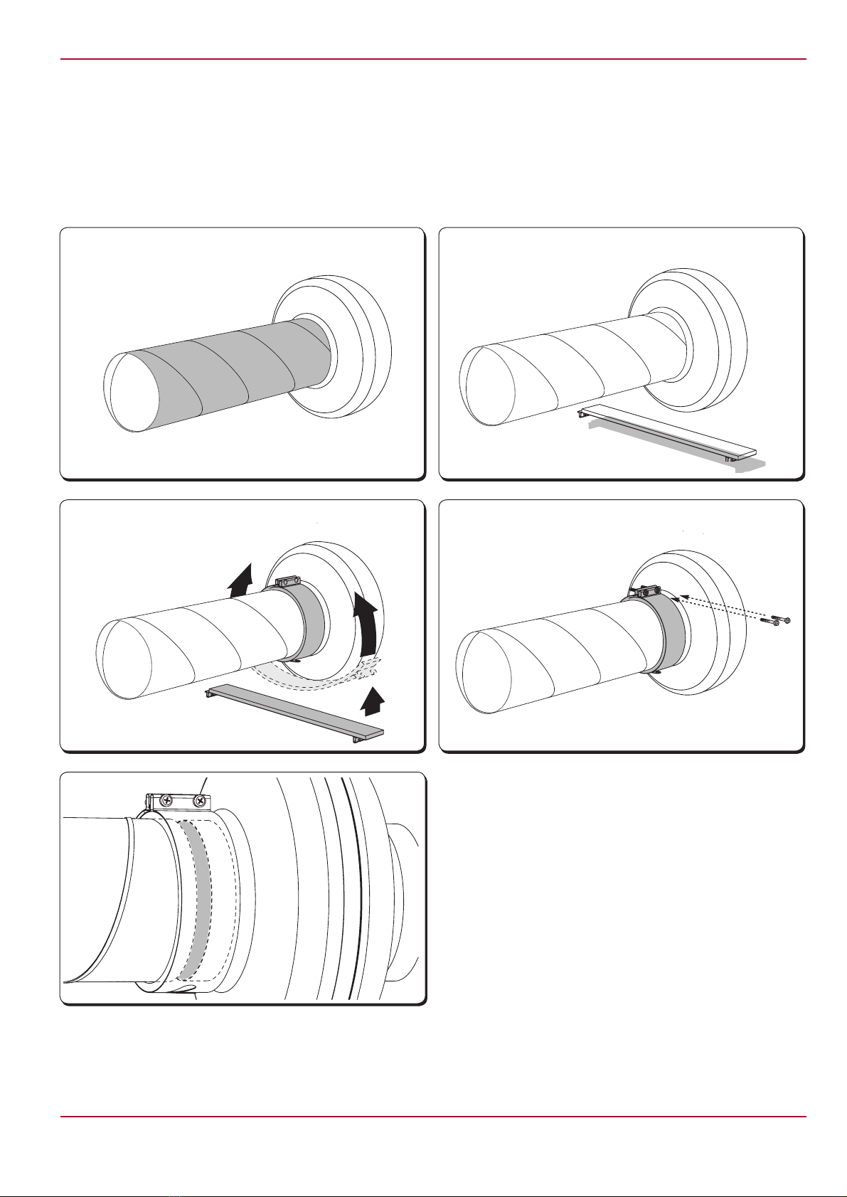
• Pour raccorder les ventilateurs au système de
conduits d’air, nous recommandons d’utiliser
des accessoires : les manchettes (Fig. #2).
Cela réduira les vibrations du dispositif sur le
système de conduits d’air et l’environnement.
• Nous conseillons d’utiliser des filtres pour
réduire l’accumulation de la saleté sur la
turbine du ventilateur. La saleté accumulée
dérègle l’équilibre de la turbine et des vibra-
tions apparaissent. Cela peut provoquer un
disfonctionnement du moteur du ventilateur.
• S’il y a une possibilité que le condensat ou
l’eau entre dans la centrale, il est nécessaire
d’installer des mesures de protection externes.
• Si le condensat ou l’eau a la possibilité de
pénétrer dans l’unité, des mesures de protec-
tion externe doivent être installées.
• Les centrales comportent des parties rotatives
et sont connectées au réseau d’alimentation
électrique. Cela peut provoquer un risque
pour la santé et la vie des personnes. Par
conséquent, il est nécessaire de respecter les
exigences de sécurité en effectuant les travaux
de montage. En cas de doute concernant
le montage sûr et la sécurité du dispositif,
s’adresser au fabricant ou à son représentant.
• Les travaux de montage ne peuvent être
effectués que par du personnel qualifié et
expérimenté.
• S’assurer que les données du réseau électrique
correspondent aux données de l’étiquette du
dispositif collée sur le panneau de la centrale.
• Le câble d’alimentation choisi doit correspon-
dre à la puissance de la centrale.
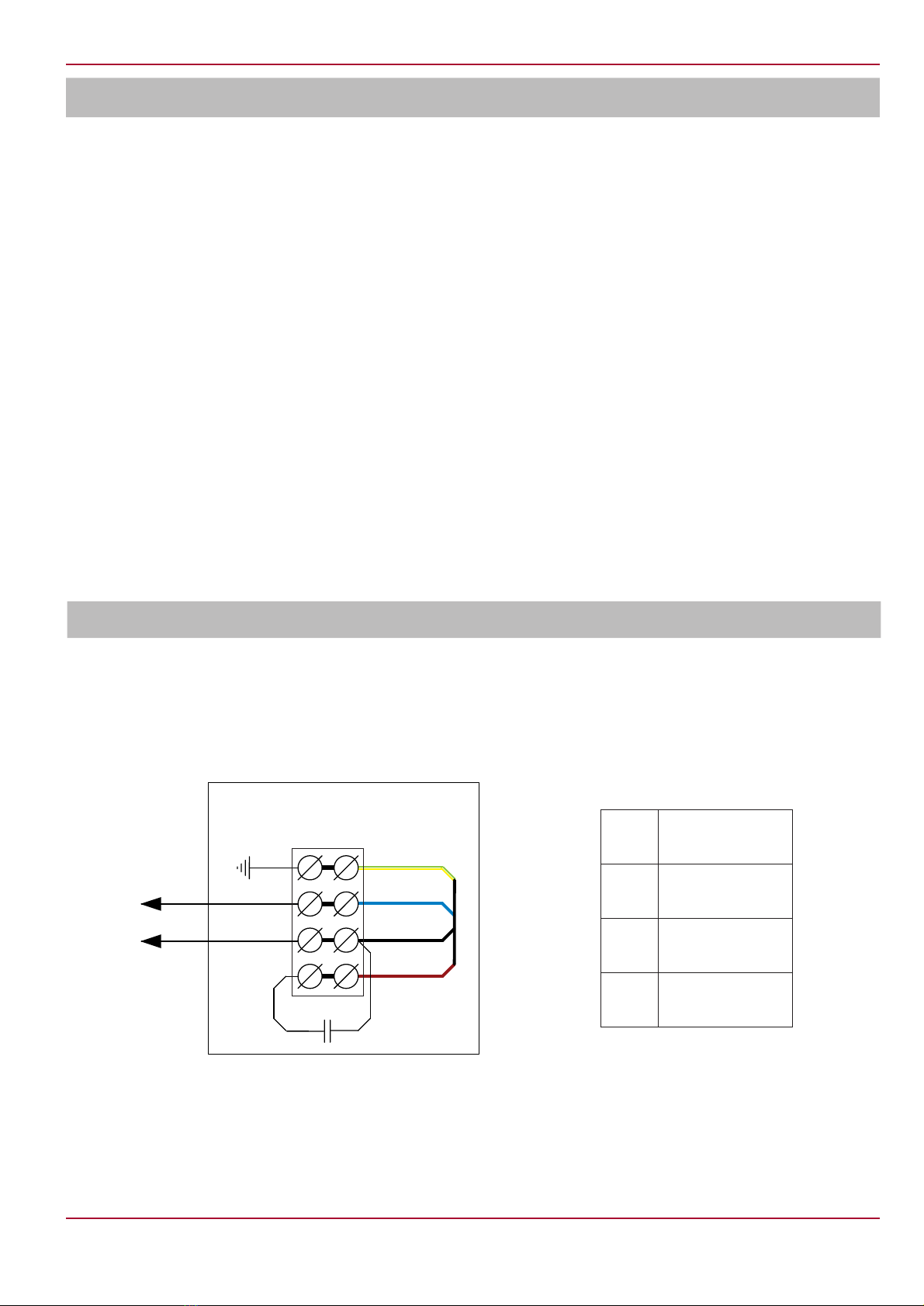
• Il est nécessaire de connecter la centrale selon
le schéma de branchement électrique établi, in-
diqué dans ce document et comme représenté
sous le couvercle du boîtier du branchement
électrique (Fig. #3).
• Avant la connexion, il est nécessaire de
s’assurer si le schéma de branchement
électrique de ce document correspond au
schéma indiqué sous le couvercle du boîtier
de branchement électrique. Si ce n’est pas le
cas, il est strictement interdit de connecter la
centrale et il faut s’adresser au fabricant ou
son représentant.
• Il est nécessaire de connecter le dispositif de
protection externe (interrupteur automatique
ou fusible) avec un courant de déclenchement
1,5 fois supérieur au courant maximal de la
centrale (indiqué sur l’étiquette du produit).
• La centrale doit être connectée à la terre
• Si un régulateur de vitesse est utilisé pour
le moteur de la centrale, il est nécessaire de
s’assurer qu’il garantit un fonctionnement sûr
du moteur.
• Il est nécessaire de garantir une vitesse mi-
nimale du moteur, près duquel s’ouvrent les
clapets d’extraction de retour (si ceux-ci ont
été montés).
• Монтажные работы должны выполнять-
ся только обученным и квалифицирован-
ным персоналом.
• Устройство должно быть смонтировано
прочно и жестко, что обеспечит его безо-
пасную эксплуатацию.
• Устройство включается в систему возду-
ховодов.
• Необходимо обеспечить защиту от со-
прикосновения с крыльчаткой работаю-
щего вентилятора (для этого используют-
ся специально изготавливаемые аксессу-
ары или подбирается необходимая дли-
на воздуховода).
• Не подключайте колена вблизи фланцев
подключения устройства. Минимальный
отрезок прямого воздуховода между
устройством и первым разветвлением
воздуховодов в канале забора воздуха
должен составлять 1хD, а в канале выброса
воздуха 3хD, где D – диаметр воздуховода.
• Вентилятор может устанавливаться в лю-
бом положении (#1-6 рис.).
• При подключении воздуховодов обратите
внимание на направление воздушного по-
тока, указанное на корпусе изделия.
• При установке вентиляторов на стенах
или потолке, рекомендуется использова-
ние специально изготавливаемых аксес-
суаров – держателей (#1 рис.).
• При подключении вентиляторов в систе-
му воздуховодов рекомендуется исполь-
зование аксессуаров – хомутов (#2 рис.).
Это снизит колебания, передаваемые от
устройства в систему воздуховодов и в
окружающую среду.
• Советуется использование воздушных
фильтров, снижающих накопление грязи
на крыльчатке вентилятора. Накопившаяся
грязь нарушает баланс крыльчатки, возни-
кают вибрации. Это может вызвать полом-
ку двигателя вентилятора.
• Если существует возможность попадания в
устройство конденсата или воды, необходи-
мо установить внешние средства защиты.
• Устройства имеют крутящиеся части и под-
ключаются к электросети. Это может пред-
ставлять опасность жизни и здоровью чело-
века. Поэтому при выполнении монтажных
работ необходимо соблюдать требования
безопасности. В случае возникновения со-
мнений в безопасном монтаже и эксплуата-
ции изделия просим обращаться к произво-
дителю или его представителю.
• Монтажные работы должны выполнять-
ся только обученным и квалифицирован-
ным персоналом.
• Убедитесь, что параметры подключаемой
электросети соответствуют спецификации
на наклейке изделия на корпусе устройства.
• Выбранный электропровод должен соответ-
ствовать мощности устройства.
• Устройство должно быть подключено в со-
ответствии со схемой электрического под-
ключения, которая приведена в настоящем
документе, а также изображена под крыш-
кой клеммной коробки (#3 рис.).
• Необходимо подключить внешнее устрой-
ство защиты (автоматический выключатель
или предохранитель), ток срабатывания
которого подбирается в 1,5 раза больше
максимального тока устройства (указанный
на наклейке изделия).
• Устройство должно быть заземлено.
• Если используется регулятор скорости дви-
гателя устройства, необходимо убедить-
ся, что он гарантирует безопасную рабо-
ту двигателя.
• Необходимо обеспечить минимальную ско-
рость двигателя, при которой открывают-
ся (если они смонтированы) заслонки об-
ратной тяги.
• Installation should be performed only by the
experienced and qualified personnel.
• To ensure the safe operation the installation of
the device should be firm and tight.
• The device is connected to the duct system.
• It is necessary to provide protection against the
contact with the operating fan impeller (to en-
sure this, special accessories should be used
or appropriate duct length should be selected).
• Do not connect the elbows near the connection
flanges of the unit. The minimum distance of
the straight air duct between the unit and the
first branch of the air duct in the suction air duct
must be 1xD, in air exhaust duct 3xD, where
D is diameter of the air duct.
• The fan can be mounted in any position (see
Fig. #1-6).
• When connecting the ducts please observe
the air flow direction indicated on the housing
of the device.
• When mounting the fans onto the walls or
ceilings it is recommended to use special
supporting accessories (see Fig. #1)
• When connecting the fans into the duct sys-
tem it is recommended to use the accessory
clamps (see Fig. #2). This will help to reduce
the vibration of the device transmitted into the
duct system and the environment.
• It is recommended to use air filters that reduce
the amount of dirt accumulating on the fan’s
impeller. The accumulated dirt affects the
balance of the impeller which may cause vibra-
tion. This may be the reason for the improper
operation of the fan motor.
• If there is a possibility for condensate or
water to access the unit, external protective
measures shall be fitted.
• The devices are equipped with rotating parts
and are connected to the electric power supply.
This may cause risk for human health and life.
Therefore, when performing the installation, it
is necessary to follow the safety requirements.
If you have doubts regarding the safe instal-
lation and operation of the device, please
contact the manufacturer or its authorized
representative.
• Installation should be performed only by ex-
perienced and qualified personnel.
• Make sure that the characteristics of the
power supply correspond to the information
provided on the product label on the housing
of the device.
• The selected power cable should be in accord-
ance with the capacity of the device.
• The device should be connected in accord-
ance with the specially determined power
connection scheme that is included into this
document and indicated under the cover of the
power connection case (see Fig. #3).
• It is necessary to connect the external protec-
tive component (automatic connector or fuse)
with the operating current that is 1.5 times
greater than the maximum current of the
device (indicated on the label of the device).
• The unit must be adequately grounded.
• If the device motor speed controller is used, it
is necessary to make sure that it can guarantee
the safe operation of the motor.
• It is necessary to ensure the minimum speed
of the motor that triggers the opening of the
backward extract valves (if installed).
• Montagearbeiten dürfen ausschließlich vom
geschulten und qualifizierten Personal durch-
geführt werden.
• Die Anlage muss fest und starr montiert wer-
den, dadurch wird die sichere Nutzung der
Anlage gesichert.
• Die Anlage wird an das System der Luftkanäle
angeschlossen.
• Die Flügel des funktionierenden Ventilators
müssen gegen jeden Berührungskontakt
geschützt werden (zu diesem Zweck werden
Zubehör, das speziell dazu hergestellt wird,
oder das Luftkanal mit einer erforderlichen
Länge benutzt).
• Schließen Sie keine Bögen in der Nähe von
Geräteanschlussstutzen an. Der Mindestab-
stand einer geraden Luftleitung zwischen dem
Gerät und der ersten Abzweigung in der Zu-
luftleitung muss 1xD, in der Abluftleitung 3xD
betragen (D - Durchmesser der Luftleitung).
• Der Ventilator darf in jeder Stellung montiert
werden (Abb. #1-6).
• Beim Anschluss der Luftkanäle muss man auf
die Richtung des Luftstroms achten, der am
Gehäuse der Anlage angegeben ist.
• Für die Wand- oder Deckenmontage des
Ventilators wird das Sonderzubehör – Halter
empfohlen (Abb. #1).
• Zum Anschluss des Ventilators in das Luft-
kanalsystem wird die Nutzung des Zubehörs
– Rohrbefestigungsmanschette (Abb. #2)
empfohlen. Dadurch werden die Schwingun-
gen, die von der Anlage an das Luftkanalsys-
tem und Umgebung weitergegeben werden,
reduziert.
• Wir empfehlen Luftfilter zu benutzen, die die
Schmutzansammlung auf den Ventilatorflü-
geln verringern. Die Schmutzansammlung
gefährdet das Gleichgewicht und führt zu
Vibrationen. Dies kann die Störung des Ven-
tilatormotors hervorrufen.
• Besteht die Möglichkeit zum Eindringen von
Kondensat bzw. Wasser ins Gerät, sind exter-
ne Schutzvorrichtungen anzubringen.
• Die Anlagen haben Drehteile und werden an
das Stromversorgungsnetz angeschlossen.
Sie können Risiko für die menschliche Ge-
sundheit und Leben darstellen. Darum müssen
Sicherheitsforderungen bei der Montage
beachtet werden. Sollten Unklarheiten oder
Zweifel wegen der sicheren Montage und Nut-
zung der Anlage entstehen, wenden Sie sich
bitte an den Hersteller oder seinen Vertreter.
• Die Montagearbeiten dürfen ausschließlich
durch geschultes und qualifiziertes Personal
vorgenommen werden.
• Vergewissern Sie sich bitte, dass die Angaben
des anzuschließenden Stromversorgungs-
netzes den Angaben auf dem Aufklebeschild
des Herstellers auf dem Gehäuse der Anlage
entsprechen.
• Das gewählte Stromversorgungskabel muss
der Leistung der Anlage entsprechen.
• Die Anlage muss nach dem festgestellten
Stromanschlussschema angeschlossen wer-
den, das in diesem Dokument angegeben und
unter dem Deckel vom Stromanschlusskasten
dargestellt ist (Abb. #3).
• Man muss ein peripheres Schutzgerät (einen
automatischen Schalter oder eine Sicherung)
anschließen, dessen Ansprechstrom um 1,5
Mal höher als der Höchststrom der Anlage
ist (angegeben auf dem Aufklebeschildschild
der Herstellers).
• Stellen Sie eine Erdung für das Gerät sicher.
• Wird ein Geschwindigkeitsregler für den
Anlagenmotor benutzt, muss man darauf
achten, ob er den sicheren Betrieb des Motors
sicherstellt.
• Die Mindestgeschwindigkeit des Motors muss
sichergestellt werden, wobei sich Rückventile
(falls eingebaut) öffnen.
Montage Монтаж Installation Montage
[ fr ] [ ru ] [ en ] [ de ]
VKR