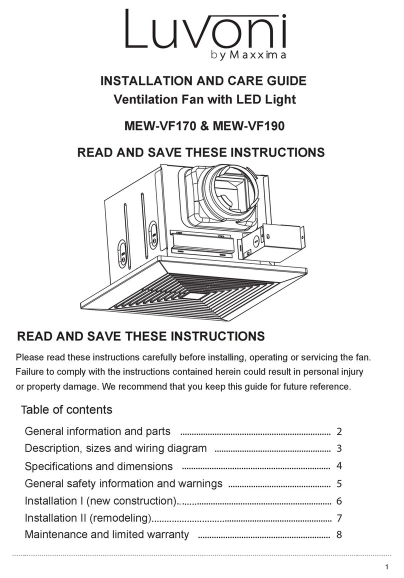
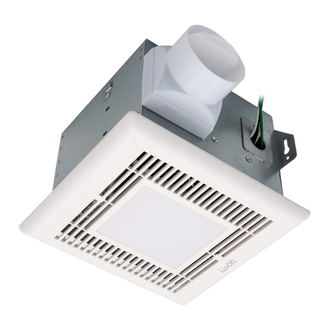
Maxxima Luvoni MEW-VF290L Assembly instructions

It is very important that you read this manual before installation for your
safety and to ensure proper performance of the unit.
Please be advised that all units should be installed by a licensed electrician.
READ AND SAVE THESE INSTRUCTIONS
General safety information
.................................................................................... 1
List of parts and accessories ............................................................................... 2
Dimensions, Specifications,Wiring diagram
....................................................... 4
Installation I( New Construction) . . . . . . . . . . . . . . . . . . . . . . . . . . . . . . . . . . . . . . . . . . . . . . . . . . . . . . . . . . . . . . . . . . . . . . . 5-6
Installation II(Remodeling) ................................................................................... 7
Cleaning the ventilation fan ................................................................................. 7
Table of Contents Pages
Planning installation............................................................................................. 3
INSTALLATION AND CARE GUIDE
Ventilation Fan with LED Light
MEW-VF290L
READ AND SAVE THESE INSTRUCTIONS

possible
16.
15.
17.
10.
14.
13.
11.
12.
I
Three Year Warranty:
Maxxima extends a 3 year limited warranty to the original purchase that the products listed are
free from defects in material and/or workmanship only. Maxxima will replace any warrantied
product to the original consumer/purchaser if the product fails because of defects due to
workmanship and/or materials within the limited warranty period. Limited warranty is not
transferable and applies to the original installation of the Maxxima product. This offer does not
constitute in any way a product guarantee and Maxxima does not hereby assume any obligation
whatsoever beyond sending a free replacement product.
Warranty Information

Grille
6
Fan
Housing

PLANNING INSTALLATION
NOTE: If installing in existing construction, you must
have access to space above and below the installation
location.
can reduce energy loss and inhibit mold growth. Fans installed with existing ducts may not achieve
their rated airflow.Do not install the ventilation fan in areas where the duct work will require
Figure(1)
The ducting from this fan to the outside of the building has a strong effect on the air flow,noise and
energy use of the fan . Use the shortest, straightest duct routing possible for best performance,
and avoid installing the fan with smaller ducts than recommended. Insultation around the ducts
Recommended to put insulation around and the fan housing to minimize the building heat loss. Seal all
the gaps around the housing with caulk or other similar material to inhibit air leakage to the exterior of
the thermal envelope of the building. Rigid sheet metal duct and the shortest path to the outside
will minimize static pressure losses and promote adequate flow.
When installing the ventilation fan in a new construction site,
install the main body of the fan and
duct work during the rough-in construction of the building. The grill should be installed after the
finished ceiling is in place.
When installing in existing construction, use the dimensions to determine required hole size for the
ceiling. The grilleedges should overlap the finished ceiling.
configurations as shown in the following figure (1): )>C!+,&-.#)7=337C8>C!+,&C>,-.#.2>8?)*?C=7=C!>4;#.;=;7=@)7=3?*8!#C5+,.D.,

Wiring Diagram 40.38
90CFM
MEW-VF290L 90CFM 1.0
Controller

1. For proper ventilation, orientate the body of the fan with the exhaust outlet
facing the desired duct direction.
DIAGRAM A
2.
Place the body of the fan against underside of joist in designated area
and secure using long screws.
3 . Add the brackets provided to the sides that are not connected to the joists
and secure to fan with short screws and joist with long screws.
DIAGRAM B
DIAGRAM C 5Installation I (New Construction)

4.
If the brackets are too short to reach the joist, the provided extensions
(DIAGRAM D) can be used for attachment.
DIAGRAM D
5. Attach the duct to the exhaust outlet of the fan. Secure with duct tape
(Diagram E) and make sure there is no air leak.
Make sure that there are no sharp bends in the duct line (Diagram F).
For 90 degrees angles, use smooth curves or break into two smaller angles
or curves (Diagram G).
DIAGRAM E DIAGRAM F DIAGRAM G
Secure with duct tape Wrong support Correct support and angle
6. Electrical installation (See wiring diagram)
Wires from the power supply to the unit should not be smaller than size 14 AWG.
The ground wire must be connected to the green wire in junction box.
The neutral wire must be connected to the white wires in the junction box.
The hot wire must be connected to the black wires in the junction box.
6For safety and efficiency of the ventilation system, avoid sharp angles and loose support.

1. In the event there is a ventilation unit with the same dimensions in the,
ceiling proceed as below:
Remove the old unit.
Check the existing duct work and electrical wiring.
Install the unit as described in
2. In the event you want to make a new opening in the existing ceiling:
Find the best location for the ventilation purpose, that is adjacent to
an accessible joist.
Make sure the chosen place has easy access to exterior air outlet (wall cap or
roof vent) and there won’t be the need to use sharp angles or long duct runs.
Make sure the chosen place duct work will not interfere with any other existing
duct work in the building.
Make sure there is no electrical wiring or any pipes behind the chosen place.
Open the optimal place.
Construct strong support beams for the unit (make sure it is strong enough for
the weight of the unit).
Provide the duct system.
Provide the electrical wiring.
Unit cleaning periodically is advisable since dust,molds.grease and other dirt
Cleaning of the ventilation fan
Follow the instructions on Installation l.
particles can affect the conductivity of the air in the unit.
The procedure should be done as follows :
Remove the plastic cover/grille.
Wipe the cover using a damp cloth with mild detergent (like liquid soap)
(avoid harsh detergent and avoid water from getting into light assembly).
Dry the cover with a cloth or kitchen towel.
Clean inside the unit with vacuum cleaner(motor shouldn’t be in contact with any
water or harsh chemicals and liquids.)
Dry the body with paper towel.
Put the cover back in place.
7
Installation I. Installation I. Installation I. Installation I. Installation I. Installation I. Installation I. Installation I. Installation I. Installation I. Installation I. Installation I. Installation I. Installation I. Installation I. Installation I.
Installation II (Remodeling)
Table of contents
Other Maxxima Fan manuals