ALGE-Timing TELEDATA TED-TX User manual

TELEDATA
TED-TX / TED-RX
English

TED-TX / RX Page 2
1 ...... Antenna
2 ...... Green holder with velcro tape
3 ...... LED
4 ...... Banana socket yellow: data input
5 ...... Banana socket green: signal input
6 ...... Banana socket black: common ground
7 ...... DIN-socket: data- and signal input, ext. supply input
8 ...... 3/8 inch socket for tripod fastening
9 ...... Code-switch (16 positions)
10 .... Device-key
11 .... Device-switch
12 .... Code-switch (10 positions)
13 .... Fastening screw for battery holder
14 .... Battery cover
15 .... Device sticker with device number
1 ...... Antenna
2 ...... Red holder with velcro tape
3 ...... LED
4 ...... Banana socket yellow: data output
5 ...... Banana socket green: signal output
6 ...... Banana socket black: common ground
7 ...... DIN-socket: data- and signal output, ext. supply input
8 ...... 3/8 inch socket for tripod fastening
9 ...... Code-switch (16 positions)
10 .... Device-key
11 .... Device-switch
12 .... Code-switch (10 positions)
13 .... Fastening screw for battery holder
14 .... Battery cover
15 .... Device sticker with device number
TED RX TED TX
TED RX TED TX
TED TX /RX from the bottom

TED-TX / RX Page 3
Version: E-2000-03-02 Page 3
Table of Contents
1. GENERAL .................................................................................................................................4
2. POWER SUPPLY........................................................................................................................5
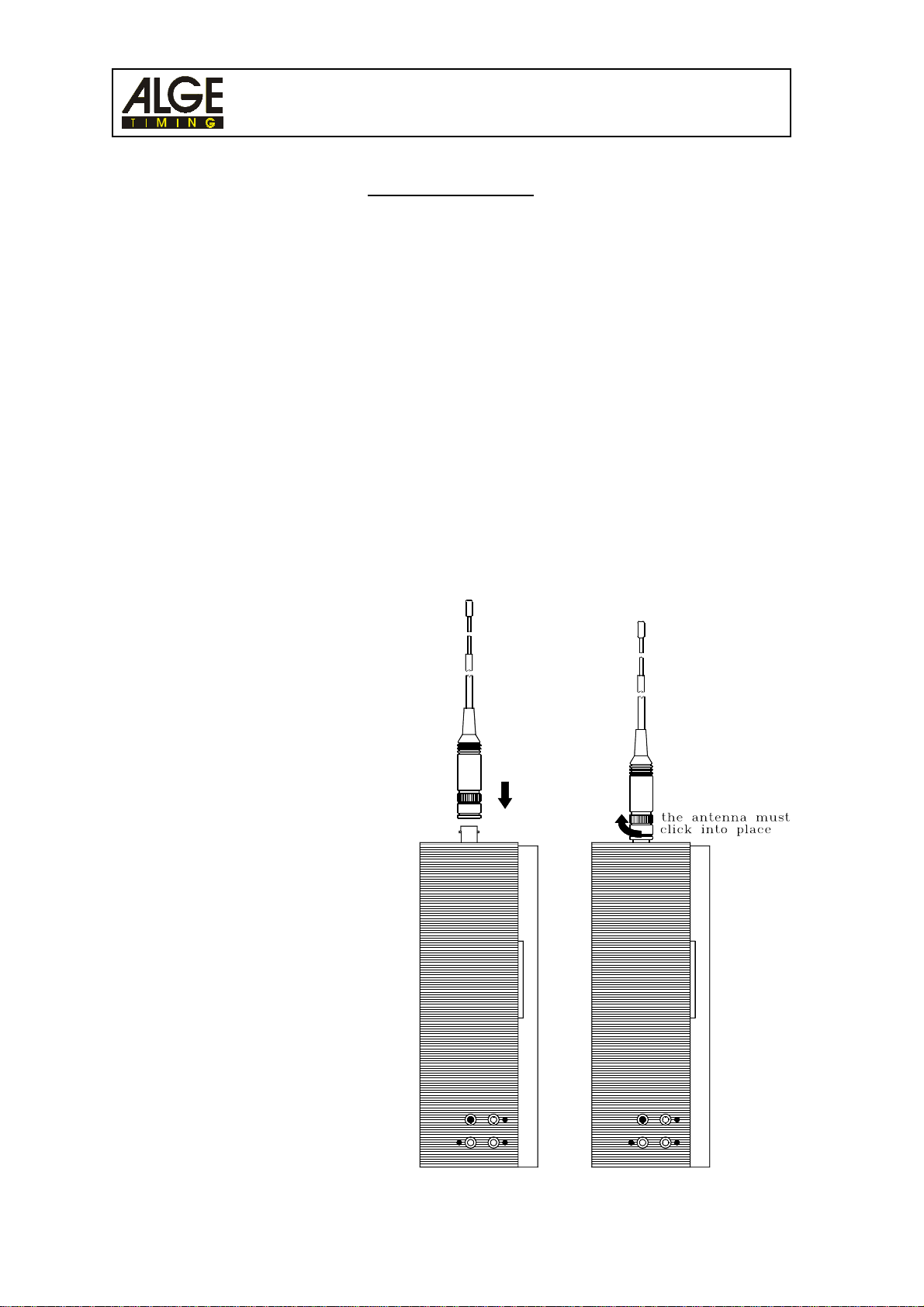
2.1. ChangingBatteries..............................................................................................................5
2.2. Using Alkaline Batteries.......................................................................................................6
2.3. Using NiCad Batteries .........................................................................................................7
2.4. External Supply ...................................................................................................................8
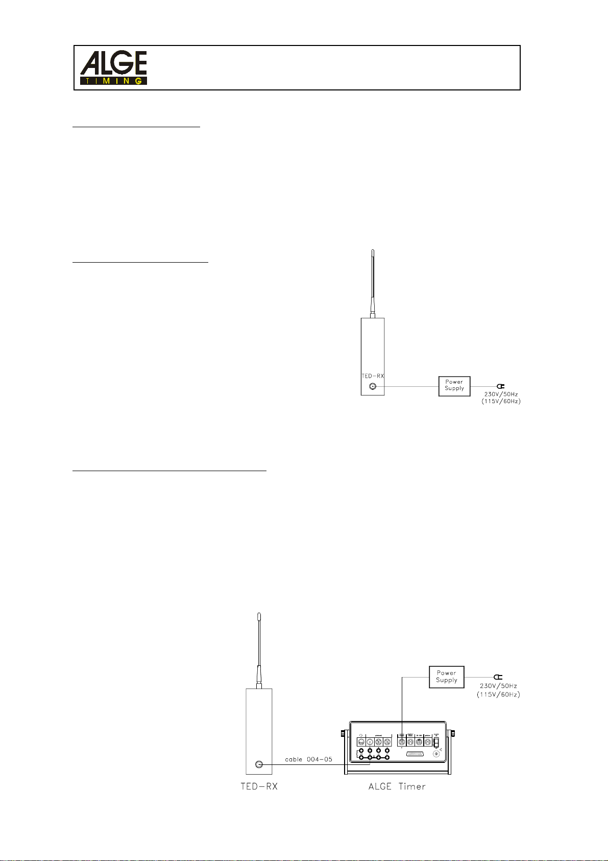
2.4.1. Direct Power Supply.................................................................................................8
2.4.2. Power Supply through the Timer ..............................................................................8
3. OPERATION .............................................................................................................................10
3.1. Setup ...............................................................................................................................11
3.2. Switching on ......................................................................................................................12
3.3. Choosing the Operation Modes .........................................................................................12
3.4. Address .............................................................................................................................13
3.5. Signal Strength Test to find the ideal setup position ..........................................................14
3.6. Interference Test ...............................................................................................................15
4. IMPULSETRANSMISSION.......................................................................................................16
4.1. Impulse Transmission from a Startgate .............................................................................17
4.2. Impulse Transmission from a Start-Photocell ....................................................................18
4.3. Impulse Transmission from a Finish-Photocell ..................................................................18
4.4. Impulse Transmission from a Photocell used for Start and Finish .....................................18
4.5. Impulse Transmission with two Photocells for Start and Finish .........................................19
4.6. Impulse Transmission with one Photocell for Start and Finish..........................................19
4.7. Impulse Transmission for more than two Timing Channels with RX-C10 ..........................20
5. DATA TRANSMISSION.............................................................................................................22
5.1. Data Transmission 1 Second ............................................................................................22
5.1.1. Data Transmission from a Timer S4 to a Timer S4.................................................23
5.1.2. Data Transmission from a ALGE Timer to a Printer P4A........................................24
5.2. Data Transmission 0.1 Seconds........................................................................................25
5.2.1. Data Transmission from an ALGE Timer to an ALGE Display Board .....................25
5.2.2. Data Transmission from a Comet to an ALGE Football Score Board .....................26
5.2.3. Data Transmission from an ALGE Timer to a Comet Parallel Display ....................26
5.2.4. Data Transmission from an ALGE Timer to a PC ...................................................26
5.3. Data Transmission 2400 Baud ..........................................................................................27
5.4. Data Transmission 4800 Baud ..........................................................................................27
5.5. Data Transmission Direct ..................................................................................................28
6. TECHNICAL DATA....................................................................................................................30
TED manual copyright by: ALGE-TIMING
AUSTRIA

TED-TX / RX Page 4
1. GENERAL
Use: Wireless transmission of timing impulses and data
Radio Frequency: 70 cm band (standard frequency= 433,500 MHz)
TED-Types: TED-TX10: Teledata Transmitter with a RF output power of 10 mW,
about 1.5 km reach, built in l/4 antenna
TED-TX400: Teledata Transmitter with a RF output power of 10 mW,
about 1.5 km reach, antenna connection through BNC
socket
TED-RX: Teledata receiver (for TED-TX10 and TED-TX400
identical), built in l/4 antenna
Minimum configuration: 1 TED-TX and 1 TED-RX
Additions: additional TED-TX for impulse- or data transmission
additional TED-RX for data transmission
RX-C10: impulse transmission for two and more timing channels
Identification for TED-TX: device sticker (15) and green holder (2)
Identification for TED-RX: device sticker (15) and red holder (2)
Information on the device sticker: - device type - device frequency
- device number - power output (only on TED-TX)
Impulse transmission: The impulse transmission works direct from any ALGE impulse
device to any ALGE timing device.
Data transmission ALGE 1 Sec.: The TED-TX sends each data string 10 times. It sends per
second one different data string.
Data transmission ALGE 0.1 Sec.:The TED-TX sends each data string 1 time. It sends per 0.1
second one data string.
Data transmission 2400 Baud: Data transmission with 2400 Baud, where it needs a code at
the beginning and end of each data package.
Data transmission 4800 Baud: Data transmission with 4800 Baud, where it needs a code at
the beginning and end of each data package.
Data transmission Direct: Transmits all data, the transmitter is always turned on.
System test: signal strength test
interference test
Power supply: 6 batteries (type AA) or
6 NiCd batteries (type AA)
external supply

TED-TX / RX Page 5
Version: E-2000-03-02 Page 5
2. POWER SUPPLY
There are two ways to supply the TED:
- internalsupply: with six batteries or NiCad (type AA)
- external supply: with a ALGE charger or from a ALGE timing device or 12 Volt Battery
2.1. Changing Batteries:
- You will reach the battery compartment from the bottom.
- Screw the fastening screw counter-clockwise.
- Remove the battery cover.
- Remove the batteries (hold the TED upright, so the batteries fall
out of the battery compartment).
- Insert new (or loaded) batteries (six batteries). Be aware of
polarity - see picture in the battery compartment.
- Put battery cover on and screw fastening screw clockwise. You
must turn the screw until the stop (the last turns are harder,
because of the force of the spring).

TED-TX / RX Page 6
2.2. Using Alkaline Batteries:
Each TED needs 6 Alkaline batteries (type AA). The LED (3) shows the battery capacity during
normaloperation.
Blinking of LED (3):
The LED has in the signal
strength test a different
function (see point 3.5).
The TED switches automatically off, as soon as the battery voltage is lower than 5 Volt!
Attention: If you buy replacement batteries for a event, be aware that you need for each TED
(receiver and transmitter) six batteries.
Empty Battery Warning:
TED-TX: When the LED (3) switches to red on the TX, it sends along with the next impulse or data
string a message to the TED-RX. The TED-RX then turns on an alternating high and low
sound to indicate that the TED-TX needs new batteries.
TED-RX: When the LED (3) switches to red an alternating high and low sound indicates that the
TED-RX needs new batteries. Make sure you check both units every time you hear teh
alternatingsound.
Working duration of batteries:
The measurements shown bellow are made with Alkaline batteries (type Energizer) at room tem-
perature (25°C, 77 F). Please notice that the capacity of batteries drops fast at low temperatures (at
-20°C (-4F) about 20 % capacity).
Color of LED (3) Battery Capacity
green 35 to 100 %
border between green and orange about 35 %
orange 20 to 35 %
border between orange and red about 20 %
red less than 20 %
off empty
TED-TX10 without photcell 1 impulse per minute about 300 hours
TED-TX10 with photocell 1 impulse per minute about 66 hours
TED-TX10 --- 1 data transmission per minute about 270 hours
TED-TX10 --- continues data transmission about 54 hours
TED-TX400 without photcell 1 impulse per minute about 270 hours
TED-TX400 with photocell 1 impulse per minute about 60 hours
TED-TX400 --- 1 data transmission per minute about 54 hours
TED-TX400 --- continues data transmission about 6 hours
TED-RX --- in all equal about 54 hours

TED-TX / RX Page 7
Version: E-2000-03-02 Page 7
2.3. Using NiCd Rechargeable Batteries:
Each TED needs 6 NiCad rechargeable. You cannot charge the batteries inside the device. To load
the batteries you need a separate charger. The LED (3) shows the battery capacity during the
normaloperation.
Blinking of LED (3):
The LED has in the signal strength
test a different function (see point 3.5).
The TED switches automatically off, as soon as the battery voltage is lower than 5 Volt!
Empty Battery Warning:
TED-TX: TED-TX: When the LED (3) switches to red on the TX, it sends along with the next
impulse or data string a message to the TED-RX. The TED-RX then turns on an alternat-
ing high and low sound to indicate that the TED-TX needs new batteries.
TED-RX: When the LED (3) switches to red an alternating high and low sound indicates that the
TED-RX needs new batteries. Make sure you check both units every time you hear teh
alternatingsound.
Working duration of batteries:
The measurements shown bellow are made with NiCad batteries (type Panasonic 700 mAh) at
room temperature (25°C, 77 F). Please notice that the capacity of batteries drops fast at low tem-
peratures (at -20°C (-4F) only about 80 % capacity).
Color of LED (3) Battery Capacity
green 15 to 100%
border between green and orange about 15 %
orange 5 to 15 %
border between orange and red about 5 %
red less than 5 %
off empty
TED-TX10 without photcell 1 impulse per minute about 100 hours
TED-TX10 with photocell 1 impulse per minute about 22 hours
TED-TX10 --- 1 data transmission per minute about 90 hours
TED-TX10 --- continues data transmission about 18 hours
TED-TX400 without photcell 1 impulse per minute about 90 hours
TED-TX400 with photocell 1 impulse per minute about 20 hours
TED-TX400 --- 1 data transmission per minute about 18 hours
TED-TX400 --- continues data transmission about 2 hours
TED-RX --- in all equal about 18 hours

TED-TX / RX Page 8
2.4. External Supply:
You can supply the TED from a power supply.
Voltage for Power Supply: TED-TX10: +6,5 to 28 VDC
TED-TX400: +9 to 15 VDC
TED-RX: +6,5 to 28 VDC
2.4.1. Direct Power Supply:
You can supply the TED from the following ALGE chargers:
- Power Supply NLG8
- Power Supply NLG4
- Power Supply LG-Comet (do not use for TED-TX400)
- Net-Battery-Device NBG
Plug the charger at the mains and TED (DIN socket 7)
Attention: Depending on the voltage of you county you need a ALGE power supply for 230 V / 50
Hz or 115 V /60 Hz. On voltage will be written on the ALGE power supply.
2.4.2. Power Supply through the Timer:
When using the mode "Impulse Transmission" it is possible to supply the TED-RX from the power
supply of the ALGE Timing device. Use cable 004-05 between TED-RX and timer.
Attention:
You can supply the TED-RX only if the timer is external supplied. From the internal batteries of the
timer you cannot supply the TED-RX.
You cannot supply a Comet and TED-RX with the LG-Comet.
- Plug power supply at mains
and timer
- Connect TED-RX and timer
with cable 004-05

TED-TX / RX Page 9
Version: E-2000-03-02 Page 9

TED-TX / RX Page 10
3. OPERATION
There are three different types of Teledata TED. Each TED shows the type on the area, where you
have the antenna.
TED-TX10:
l/4-antenna screwed on TED
TED-TX400:
l/2-antenna with BNC-connection
TED-RX:
l/4-antenna screwed on TED
BNC-Antenna-Connection for TED-TX400:
Fasten the Antenna:
- put antenna on BNC-plug of TED-TX400
- rotate the antenna until it falls into the plug
- hold the antenna on the lower section and
turn it clockwise until the antenna clicks into
position
Remove the Antenna:
- hold the antenna on the lower
section and turn until the
antenna clicks out or place
- remove antenna

TED-TX / RX Page 11
Version: E-2000-03-02 Page 11
3.1. Set up:
The useful distance of the TED system depends on signal strength. You have to spend a reason-
able effort to properly mount both the TX and RX units.
the position of the TED-TX and TED-RX. Mostly you improve the receiver signal strength by moving
the TED-TX and TED-RX to the right position (high signal strength = high impulse or data safety).
There are more possibilities to set up the TED:
Wrong:
The antenna must always point upwards.
Wrong:
The TED-TX and RX should never stand direct on
the floor. This decreases the reach.
Wrong:
Parts next to the antenna are not allowed.
Good:
Use the velcro to tape the TED to a post.
Good:
Fasten the TED on a tripod (3/8 inch)
Good for small an medium distances:
Use the TED-Holder with the photocell
holder (or a tripod) to fasten the TED-TX
and a photocell.

TED-TX / RX Page 12
3.2. Switching on:
Normal Mode:
- switch device-switch (11) on
- TED works in the impulse transmission mode
Test-Mode:
- press device-key (10)
- device-switch (11) to position ON, LED (3) must blink
- release device-key (10)
- test mode switches automatically off after one minute,
manually you can switch it off with device-key (10).
Impulse Transmission:
device-switch (11) to position ON, LED (3) must blink
Data Transmission ALGE 1 Sec.:
- device-switch (11) to position ON, LED (3) must blink
- when a data string with the right format arrives at the
TED-TX it switches to this mode.
Data Transmission ALGE 0.1 Sec.:
- set code switch (12) from TED-TX and RX on position 1
- device-switch (11) to position ON, LED (3) must blink
Data Transmission 2400 Baud:
- set code switch (12) from TED-TX and RX on position 3
- device-switch (11) to position ON, LED (3) must blink
- transmission of each data string with 2400 Baud
- each data string needs a code at the start and end
Data Transmission 4800 Baud:
- set code switch (12) from TED-TX and RX on position 4
- device-switch (11) to position ON, LED (3) must blink
- transmission of each data string with 4800 Baud
- each data string needs a code at the start and end
Data Transmission "Direct":
- set code switch (12) from TED-TX and RX on position 6
- device-switch (11) to position ON, LED (3) must blink
- transmission of each data string (with 2400 or 4800 Baud)
3.3. Choosing the Operation Modes:
You get as well into the signal strength test by making three short cuts between the green (5) and
black (6) banana socket within a short time..
Switch Signale Mode Data Mode
position 0: data transmission ALGE 1 sec.
position 1: data transmission ALGE 0.1 sec.
position 0 to 9 position 2: no function
code switch (12) to select the position 3: data transmission 2400 Baud
timing channel position 4: data transmission 4800 Baud
position 6: data transmission direct
position 7 to 9: no function
code switch (9) for address for address
device key (10) field strength on/off transmit last data string again

TED-TX / RX Page 13
Version: E-2000-03-02 Page 13
3.4. Address:
The code-switch (9) to address the TED is located in the
bottom and has 16 switch positions. Within a system all
TED-TX and TED-RX need the same address.
Together with the TED you will receive a
small screwdriver. It is used to operate
the code-switch (9) and (12). The arrow
of the switch shows always the switch
position. The factory adjustment is 0.
If different ALGE TED-systems are used in the same area, it is important that every system works
on a different address. The address protects from wrong impulses or data, but other impulse or data
strings can block the receiver.
There is the possibility that you could lose an impulse, if there is another system in use that has a
stronger signal. The only guaranteed way to prevent interferance is by using a totally separate
frequency. This can be ordered by your ALGE dealer.
e.g. Impulse transmission of the start signal::
You must set the same address for TED-TX and TED-RX.
Code-Switch (9) Address
switch position = 0 address = 0
switch position = 1 address = 1
switch position = 2 address = 2
switch position = 3 address = 3
switch position = 4 address = 4
switch position = 5 address = 5
switch position = 6 address = 6
switch position = 7 address = 7
switch position = 8 address = 8
switch position = 9 address = 9
switch position = A address = A
switch position = B address = B
switch position = C address = C
switch position = D address = D
switch position = E address = E
switch position = F address = F

TED-TX / RX Page 14
3.5. Signal Strength Test to find the ideal Position:
Trouble free operation of the TED-system depends on spending time to properly install the TX and
RX.
Attention: You can only test the signal strength in the impulse transmission mode.
How do you start the signal strength test:
- Turn the TED-TX with device-switch (11) on.
- Press the device-key (10) of the TED-TX .
- Fasten the TED-TX in a good position (see page 11).
- Turn the TED-RX with device-switch (11) on.
- The loudspeaker of the TED-RX has now a sound and the LED blinks.
> As higher the sound, as higher (better) the signal strength.
> If the LED (3) blinks green: high signal strength from the TED-TX.
> If the LED (3) blinks orange: low signal strength from the TED-TX.
> If the LED (3) blinks red: very low or no signal strength from the TED-TX.
> If you hear voices in the speaker it means, that this frequency is being used for talking. This
might cause trouble, you might lose data or impulses.
- The signal strength test ends automatically through a signal of the TED-TX after 1 minute (or
when you press device key (10) of the TED-TX).
Always try moving the TED-RX first. If you cannot find a proper signal strength, then try moving the
TED-TX. If it still fails then you have to reduce the distance or modify your application. Remember
that you can connect the TED-RX to any existing wiring.
You can only judge the signal strength at the TED-RX!
Attention - please notice if you have a short distance between TED-TX and TED-RX:
In order to work without troubles make sure that the distance between TED-TX and TED-RX is more
than 5 Meters. Otherwise it could overmodulate the receiver. For the TED-TX400 you should have a
minimum distance of 10 m.

TED-TX / RX Page 15
Version: E-2000-03-02 Page 15
3.6. Interference Test:
This mode is designed to allow you to test for interferance from other radios or to determine if data
is being transmitted. This can be a handy way to check for problems during an event. The impulses
are still being recived as normal.
If you press the device-key (10) of the TED-RX for about half a second, it switches the speaker on.
You can now listen for speech or data.
The LED shows the signal strength of the received signal. The naturally red LED turns green with
good data reception and orange with questionable data. A single impulse will not register fast
enough to see it.
To turn the interference test off press again device-key (10).
Attention: The TED-RX has double power consumption during this mode.

TED-TX / RX Page 16
4. IMPULSE TRANSMISSION
The impulse transmission works direct from any ALGE-impulse trigger to ALGE timer by radio.
Each impulse transmission through the TED
has a constant delay of 0.100 seconds.
Minimum error: 0.001 second
- If you transmit only the start impulse with the TED you must add to each run time 0.1 seconds.
- If you transmit only the finish impulse with the TED you must subtract from each run time 0.1
seconds.
- If you transmit the start- and finish impulse you get the exact run time.
Attention:
For time trail events such as cycling, sking, etc the delay is constant for every competitor. Therefore
you can use a single transmitter without compromising the results. It is only important where you are
trying to measure a record time or speed. Be aware of the limitations of a single transmitter prior to
your event.
The TED-TX and TED-RX is blocked after the beginning of the impulse for 0.1 seconds. This means
each further impulse transmitted with TED-TX is lost during this time.
Double impulse protection:
The TED-TX has a built in
double impulse protection. This
prevents double impulses made
by a bad switch. The double
impulse protection time is 0.05
seconds.
a Contact triggering at the beginning
of the impulse
b Contact triggering at the end of the
impulse
c Duration of impulse plus contact
triggering
d Double impulse protection time (50 ms)
e Double impulse protection time stops, because the 0.05 seconds are not finished
Checking the impulse transmission:
TED-TX: During the transmission of a timing impulse the LED (3) blinks longer as normal.
TED-RX: When it receives an timing impulse the LED (3) blinks longer as normal.
Safety of an Impulse Transmission:
When you use the impulse transmission the TED replaces the cable between the impulse trigger
and the timer. You must know, that radio (TED) is easy to disturb. This means that you do not
receive at the timer the signal in case of a disturbance. When you use the TED to transmit the
impulses you will never have the same safety as with wires.

TED-TX / RX Page 17
Version: E-2000-03-02 Page 17
The following ALGE devices you can use as impulse trigger:
- Startgate - StartmicrophoneSM7
- Photocell - Startbeep STB1
- Tapeswitch TS - Startclock ASC1
- Touchpad TP24 or TP18 - Handswitch 023-02 or 023-10
The following ALGE timers you can use as impulse receiver:
TdC 8000: Normally use the socket A or A´ to connect cable 004-05. In special cases see the
TdC 8000 manual for help.
TdC 4000: Plug cable 004-05 at one of the four sockets that say "ext. supply / lightbeam".
Timer S4: Normally use the socket A or A´ to connect cable 004-05. In special cases see the
Timer S4 manual for help.
Timer S3: Plug cable 004-05 at one of the two sockets that say "ext. supply / lightbeam".
Comet: Plug cable 004-05 at one of the photocell sockets.
Videotimer VT2: Plug cable 004-05 at one of the two sockets that say
"ext. supply / lightbeam".
OPTI 1sw: Plug cable 004-05 at one of the four sockets that say "photocell". For the OPTI you
have to know that you can transmit only start impulses. You cannot transmit the
finish impulse, because the photocell does control the recording. With the TED you
would only record a small part of the finish arrival.
Selection of the Impulse Transmission:
With the TED-TX you can transmit two impulse channels. Normally this will be the start- C0 and
finish impulse C1 (use cable 004-05).
If you use additional with the TED the RX-C10, than you can receive up to 10 different impulse
channels with the TdC 8000 and Timer S4 (see page 20).
Attention:
The TED-system will work with any normally open modern timing devices. Although we recommend
always using ALGE devices, feel free to contact your local ALGE dealer.
4.1. Impulse Transmission from a Startgate:
- Connect Startgate and TED-TX with cable 000-05 (2-wire cable with banana plugs)
- Connect TED-RX and timer with cable 004-05 (use socket A or A´ for Timer S4 or TdC 8000).

TED-TX / RX Page 18
4.2. Impulse Transmission from a Start-Photocell:
- Connect photocell and TED-TX with cable 002-10
- Connect TED-RX and ALGE timer with cable 004-05 (use socket A or A´ for Timer S4 or TdC
8000)
4.3. Impulse Transmission from a Finish-Photocell:
- Connect photocell and TED-TX with cable 001-10
- Connect TED-RX and ALGE timer with cable 004-05 (use socket A or A´ for Timer S4 or TdC
8000)
4.4. Impulse Transmission from a Photocell used for Start and Finish:
- Connect photocell and TED-TX with cable 002-10
- Connect adapter 129-06 at the timer (use socket A or A´ for Timer S4 or TdC 8000)
- Connect adapter 129-06 at the TED-RX and set the switch on position bridge
TED-TX TED-RXPhotocell RLSc ALGE Timer
cable 001-10
START and FINISH
cable
129-06
cable
004-05
set switch
on bridge

TED-TX / RX Page 19
Version: E-2000-03-02 Page 19
4.5. Impulse Transmission with two Photocells for Start and Finish:
- Connect adapter 018--5 at the TED-TX
- Connect cable 002-10 at the start-photocell and at adapter 018--5
- Connect cable 001-10 at the finish-photocell and at adapter 018--5
- Connect adapter 129-06 at the timer (use socket A or A´ for Timer S4 or TdC 8000)
- Connect adapter 129-06 at the TED-RX and set the switch on position bridge
4.6. Impulse Transmission with one Photocell for Start and Finish:
- You need two TED-TX and one TED-RX
- Connect cable 002-10 at the start-photocell and the first TED-TX
- Connect cable 001-10 at the finish-photocell and the second TED-TX
- Connect adapter 129-06 at the timer (use socket A or A´ for Timer S4 or TdC 8000)
- Connect adapter 129-06 at the TED-RX and set the switch on position separate
TED-RX
Photocell RLS1c
ALGE Timing
Photocell RLS1c
TED-TX
START
FINISH
cable
129-06
cable
004-05
cable cable
002-10
001-10
cable
018--5
set switch
on bridge
TED-TX TED-RXPhotocell RLSc ALGE Timer
cable 001-10
Photocell RLSc TED-TX
cable 002-10
START
FINISH
cable
129-06
cable
004-05
set switch
on separate

TED-TX / RX Page 20
4.7. Impulse Transmission for more than two Timing Channels with RX-C10:
With the TdC 8000 and Timer S4 you can receive together with the RX-C10 from the TED-RX up to
10 different timing channels. Therefore you need different TED-TX. You can transmit a maximum of
two timing channels per TED-TX. At each TED-TX you need to adjust the timing channels with
code-switch (12).
You must notice, that each timing impulse blocks the transmitter and receiver for 0.1 seconds. A
further impulse from another transmitter will be ignored during this time.
Timing Channel selection with Code-Switch (12) at the TED-TX:
You need to adjust the timing channel only at the TED-TX (transmitter). You need to adjust the
timing channels with code-switch (12). Each switch position has two timing channels.
Set the switch with the small screw driver delivered together with the TED.
The switch position is shown with the arrow. The ALGE setup is always
on position 0 (e.g. picture to the left).
TED-TX TED-TX timing channel TED-TX DIN-socket TED-TX DIN-Stecker
Code-Schalter (12) banana socket timing channel timing channel
green (5) and black (6) on pin 1 on pin 2
switch position = 0 0 0 1
switch position = 1 1 1 2
switch position = 2 2 2 3
switch position = 3 3 3 4
switch position = 4 4 4 5
switch position = 5 5 5 6
switch position = 6 6 6 7
switch position = 7 7 7 8
switch position = 8 8 8 9
switch position = 9 0 0 2
This manual suits for next models
1
Table of contents