ALIARO AL-1020U User manual

Aliaro reserve the right to vary from the description given in this data sheet and shall not be liable for any errors.
www.aliaro.com
Power Switching Chassis
AL-1020U for SLSC
This document describes the ALIARO Powering Switching Chassis (AL-1020U) based on
National Instruments SLSC-12001 Chassis.
Overview
The ALIARO Powering Switching Chassis (AL-1020U) provides the power and bus network
switching used in a vehicle while also providing the ability to individually enable or bypass bus
signals to each ECU.
The AL-1020U is made to fit National Instruments (NI) Switch Load Signal Conditioning (SLSC)
system together with corresponding computer interface boards. Software control is achieved
through a Python library, pre-delivered by Aliaro.
The main purpose of the unit is to supply a test system running multiple simultaneous test
objects and to, by software, enable and disable the connected test objects.

Aliaro reserve the right to vary from the description given in this data sheet and shall not be liable for any errors.
www.aliaro.com
Contents
Overview.................................................................................................................................................. 1
Description .............................................................................................................................................. 3
Detailed description ............................................................................................................................ 3
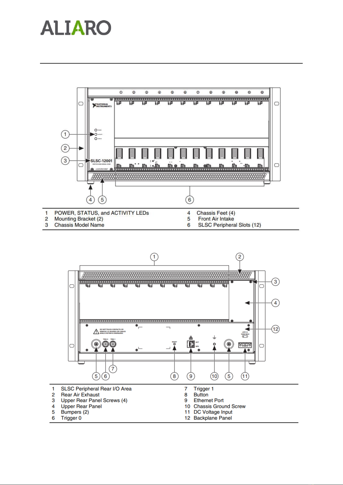
Chassis overview ................................................................................................................................. 4
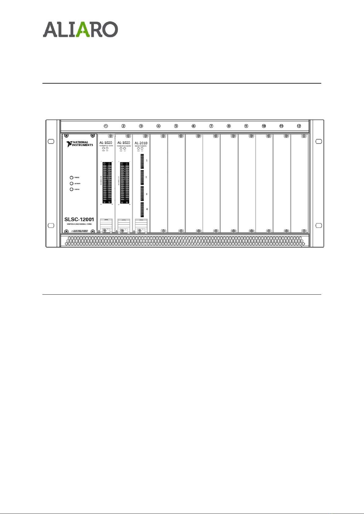
Customized chassis overview.............................................................................................................. 5
Installation requirements.................................................................................................................... 5
Chassis installation .................................................................................................................................. 6
Electromagnetic Compatibility............................................................................................................ 6
Unpacking the module ........................................................................................................................ 6
What You Need to Get Started............................................................................................................ 6
Installing additional modules .................................................................................................................. 7
Calibration ........................................................................................................................................... 7
Software installation ............................................................................................................................... 8
AL-1020U Chassis Configuration ......................................................................................................... 8
Python Library ..................................................................................................................................... 8
Contents ......................................................................................................................................... 8
Driver Installation ........................................................................................................................... 8
Methods definition / API................................................................................................................. 8
Connections........................................................................................................................................... 14
Specification .......................................................................................................................................... 15
Definition and conditions.................................................................................................................. 15
Environmental Characteristics .......................................................................................................... 16
Safety Guidelines................................................................................................................................... 16
Product Certifications and Declarations................................................................................................ 16
Environmental Guidelines ..................................................................................................................... 16

Aliaro reserve the right to vary from the description given in this data sheet and shall not be liable for any errors.
www.aliaro.com
Description
The ALIARO Powering Switching Chassis (AL-1020U) provides switching on both power I/O and
bus network channels by using the following SLSC modules:
•AL-1020, 12 channels Power Switch Board for SLSC
•AL-2010, 16 channels Bus Switch Board for SLSC
Depending on the amount of required test objects to be managed, the unit must be configured
with the appropriate number of modules.
Detailed description
For additional information about the AL-1020 Power Switch Board and AL-2010 Bus Switch
Board, visit Aliaro.com :
•ALIARO AL-1020
•ALIARO AL-2010
The test objects will need to be attached according to the figure below.

Aliaro reserve the right to vary from the description given in this data sheet and shall not be liable for any errors.
www.aliaro.com
Chassis overview
Chassis Front View
Chassis Rear View
Note - 11 requires connection with an external 24V power source

Aliaro reserve the right to vary from the description given in this data sheet and shall not be liable for any errors.
www.aliaro.com
Customized chassis overview
•Slot 1: AL-1020 Power Switch Board
•Slot 2: AL-1020 Power Switch Board
•Slot 3: AL-2010 Bus Switch Board
Installation requirements
The following knowledge is required to install and run the Power Switch Unit:
•Basic electrical knowledge
•Average skills using the Python programming language

Aliaro reserve the right to vary from the description given in this data sheet and shall not be liable for any errors.
www.aliaro.com
Chassis installation
Electromagnetic Compatibility
This product is intended for use in industrial locations. However, harmful interference may
occur in some installations, when the product is connected to a peripheral device or test object,
or if the product is used in residential or commercial areas. To minimize interference with radio
and television reception and prevent unacceptable performance degradation, install and use this
product in strict accordance with the instructions in the product documentation.
Furthermore, any modifications to the product not expressly approved by Aliaro
could void your authority to operate it under your local regulatory rules.
Unpacking the module
•Carefully inspect the shipping container and the module for damage. Check for visible
damage to the exterior and interior of the chassis. If damage appears to have been
caused during shipment file a claim with the carrier. Retain the packing material for
possible inspection and/or reshipment. If the chassis is damaged, promptly contact
Aliaro and do not install it.
What You Need to Get Started
To set up and use the module you need the following items:
Hardware
•SLSC-12001 chassis
•SLSC module(s)
•Power cable
•Power input connector
•External 24V power source
Documentation
•Power Switch Unit Specification
Caution: Do not touch the contacts or remove the I/O boards or cables while
the system is energized.
The SLSC chassis and the SLSC module do not support hot plug-in. The entire
chassis must be powered off when a module is inserted or removed.

Aliaro reserve the right to vary from the description given in this data sheet and shall not be liable for any errors.
www.aliaro.com
Installing additional modules
1. Caution Do not touch the contacts or remove the I/O boards or cables while the system
is energized.
2. Power off the main DC power source or disconnect the power source from the chassis
before installing any modules or RTIs.
3. Ensure that the chassis is powered off. The POWER LED should be off. If the POWER
LED is not off, do not proceed until it is off.
Notice The AL-1020U chassis and the SLSC modules do not support hot plug-in. The
entire chassis must be powered off when a module is inserted or removed.
4. Loosen the screws on the upper rear panel of the chassis.
5. Position the RTI backplane (if needed) at the desired slot and insert the securing screws,
but do not fully tighten them.
6. Insert the SLSC module into the same slot as its corresponding RTI while firmly holding
the RTI in place until the RTI is firmly connected to the module.
7. Repeat steps 4 and 5 for all required RTIs.
8. Fully tighten the screws for all RTIs and the upper rear panel of the chassis. Note Waiting
until all RTIs and modules are installed to fully tighten the screws ensures proper
alignment for future connections between modules and RTIs.
9. Fully tighten the two module mounting screws on each newly installed module.
10.Power on the AL-1020U chassis
Calibration
Recommended warm-up time
10 min
Calibration interval
Not required

Aliaro reserve the right to vary from the description given in this data sheet and shall not be liable for any errors.
www.aliaro.com
Software installation
AL-1020U Chassis Configuration
The AL-1020U chassis can be configured through a web-interface. The web-interface can be
used to configure settings such as:
•Network settings (IP-address, Subnet, Gateway, DNS)
•Device name
Since the chassis is based on the National Instruments SLSC-12001 Chassis, the interface is
reached by entering its IP-address (default: 192.168.1.149) into a Microsoft Silverlight compliant
web-browser. Please note that this currently excludes third party browsers such as Google
Chrome, Mozilla Firefox, Safari etc.
Recommended browser is Internet Explorer.
Python Library
Contents
The chassis communicate over ethernet utilizing the supplied ALIARO Python driver library API.
The library contains the following components:
•pws_chassi.py - Driver for the AL-1020U
Driver Installation
When the chassis is to be used, Aliaro drivers must be installed. The Power Switch Chassis
Python library is available at Aliaro.se/download.
•Download, move and unzip the drivers to your current Python program directory
(or use other absolute path import methods)
•Import the drivers to the application by using the import command in Python:
import pws_chassi
Methods definition / API
The Python driver is called by a user application that uses instances of respective module to call
methods and manipulate the connected channels E.g. :
•Switching channels on the Power Switch Board on/off
•Connect/disconnect ECUs from the CAN-bus on the Bus Switch Board.

Aliaro reserve the right to vary from the description given in this data sheet and shall not be liable for any errors.
www.aliaro.com
Each module is instantiated with the correct IP-Address (“url”) and module name (“devices”)
parameters. The defaults for these are:
•“url” - 192.168.1.149
•“devices” - AL-1020U-XXX-ModY
where X is the device serial number printed on the chassis and Y the slot number
of the card (1-3).
The following API is available for each driver:
class PowerSwitchBoard(__builtin__.object)
Methods defined here:
__init__(self, url=None, devices=None)
Method for instantiating the PowerSwitchBoard class
get_digital_state(self, channel)
Method for reading the digital state of a channel
:param channel: 0..11
:return:
get_source(self, channel)
:param channel: (int32) 0..11
:return:
set_source(self, channel, source)
:param channel: (int32) 0..11
:param source: (int32) 0(Disabled)
1(Power_1)
2(Power_2)
:return:

Aliaro reserve the right to vary from the description given in this data sheet and shall not be liable for any errors.
www.aliaro.com
Class BusSwitchBoard(__builtin__.object)
Methods defined here:
__init__(self, url=None, devices=None)
Method for instantiating the bsb class
get_bus_configuration(self, bus)
Gets the configuration of the bus
:param bus: (int32) 1..4
:return:
get_bus_operation(self, bus, con)
Gets the state of the bus.
:param bus: (int32) 1..4
:param con: (int32) 1..4
:return:
set_bus_configuration(self, state, bus)
Sets the configuration of the bus
NOTE! This configuration is only for balanced bus topology (CAN), NOT for serial such as K-
line.
:param state: (int32) 0(Open),
1(Termination),
2(Daisychain),
3(NextBus)
:param bus: (int32) 1..4
:return:
set_bus_operation(self, state, bus, con)
Sets the state of the bus.

Aliaro reserve the right to vary from the description given in this data sheet and shall not be liable for any errors.
www.aliaro.com
NOTE! Always use :"Break before make"
:param state: (inte32) 0(Connect),
1(Bypass)
:param bus: (int32) 1..4
:param con: (int32) 1..4
return:
class SlscConnection(__builtin__.object)
Methods defined here:
__init__(self)
Method for instantiating the Slsc class
abort_session(self)
Cancels a method that blocks network communications.
:return:
close_session(self)
Closes an SLSC session.
:return:
commit_properties(self)
Commits properties with pending changes to SLSC hardware. You must commit dynamic
properties for the changes to
take effect. You do not have to commit static properties because changes take effect
immediately after you set
static properties. If you set a property multiple times before you commit the property, this
method commits
only the last value.
:return:
execute_command(self, command, timeout)

Aliaro reserve the right to vary from the description given in this data sheet and shall not be liable for any errors.
www.aliaro.com
Executes command on one or more devices or physical channels.
:param command:
:param timeout:
:return:
get_property(self, prop)
Gets properties for devices.
:param prop:
:return:
get_property_physical_channels(self, prop, physical_channels)
Gets properties for physical channels.
:param prop:
:param physical_channels:
:return:
initialize_session(self)
Initializes an SLSC session.
:return:
reset_device(self)
Resets devices to default state. This method sends the specified modules a software reset
signal, reinitialize module registers to their initial value, and rereads the module's non-volatile
memory
:return:
set_host_devices(self, url, devices)
Method for updating the object-memory with communication settings
:param url:
:param devices:
:return:

Aliaro reserve the right to vary from the description given in this data sheet and shall not be liable for any errors.
www.aliaro.com
set_property(self, prop, value)
Sets properties for devices or physical channels. You must commit dynamic properties for
the changes
to take effect. You do not have to commit static properties. You can set only one property
for one or multiple
devices or physical channels.
:param prop:
:param value:
:return:
set_property_physical_channels(self, prop, physical_channels, value)
Sets properties for devices or physical channels. You must commit dynamic properties for
the changes
to take effect. You do not have to commit static properties. You can set only one property
for one or multiple
devices or physical channels.
:param prop:
:param physical_channels:
:param value:
:return:

Aliaro reserve the right to vary from the description given in this data sheet and shall not be liable for any errors.
www.aliaro.com
Connections
•Power Switch board:
The Power Switch board has connections for the 12 channels and the channel
ground. For detailed descriptions see the AL-1020 specification.
•Backplane POWER connections:
The backplane of the Power Switch boards has
connections for POWER_1 and POWER_2. These
come pre-fitted with copper plates and crimp
connectors.
•Bus Switch board:
The board has connections for 16 CAN-buses distributed over 4
groups/connectors. Each CAN-bus requires a return connection to be formed to
each ECU on respective “RTN” port pair.
PORT
LEFT
RIGHT
1
CH 1
NC
2
CH 2
NC
3
CH 3
NC
4
CH 4
NC
5
CH 5
NC
6
CH 6
NC
7
CH 7
NC
8
CH 8
NC
9
CH 9
NC
10
CH 10
NC
11
CH 11
NC
12
CH 12
NC
13
CHANNEL_GND
NC
14
NC
NC
15
NC
NC
16
NC
NC

Aliaro reserve the right to vary from the description given in this data sheet and shall not be liable for any errors.
www.aliaro.com
NOTE! The configuration of the AL-2010 in the Power Switching Chassis is a
limited version of the complete AL-2010 Bus Switch Board for SLSC.
For detailed descriptions of the full board see the AL-2010 specification.
To address a specific CAN-bus, the Python driver references “con” and “bus”.
•Con –Which connection (1-4) on the board.
•Bus –Which bus pair (B1 –B4) on the connection. Note that both RTN and OUT
must be connected to achieve proper functionality.
Specification
Definition and conditions
Warranted specifications describe the performance of a model under stated operating conditions
and are covered by the model warranty.
The following characteristic specifications describe values that are relevant to the use of the
model under stated operating conditions but are not covered by the model warranty.
•Typical specifications describe the performance met by a majority of models.
•Nominal specifications describe an attribute that is based on design, conformance
testing, or supplemental testing.
Specifications are
Typical
unless otherwise noted.
Specifications are valid under the following conditions unless otherwise noted.
LEFT PORT
RIGHT PORT
NC
NC
B4 RTN LO
B4 OUT LO
B4 RTN HI
B4 OUT HI
B3 RTN LO
B3 OUT LO
B3 RTN HI
B3 OUT HI
NC
NC
B2 RTN LO
B2 OUT LO
B2 RTN HI
B2 OUT HI
B1 RTN LO
B1 OUT LO
B1 RTN HI
B1 OUT HI

Aliaro reserve the right to vary from the description given in this data sheet and shall not be liable for any errors.
www.aliaro.com
The SLSC modules is mounted in an AL-1020U chassis with the recommended cooling
clearances and using a power supply that meets the specifications provided in the chassis user
guide. For the entire temperature range of the chassis.
Note These specifications only apply to the product as provided by Aliaro. Modifications
to the module may invalidate these. Be certain to verify the performance of modified
modules.
Caution Observe all instructions and cautions in the user documentation. Using the
model in a manner not specified can damage the model and compromise the built-in
safety protection. Return damaged models to Aliaro for repair.
Environmental Characteristics
Temperature and Humidity
Operating temperature
0 °C to 40 °C
Storage temperature range
-40 °C to 85 °C
Operating relative humidity range
10% to 90%, noncondensing
Storage relative humidity range
5% to 95%, noncondensing
Safety Guidelines
Caution Ensure that hazardous voltage wiring is performed only by qualified personnel
adhering to local electrical standards.
Caution Do not mix hazardous voltage circuits and human-accessible circuits on the
same module
Caution When device terminals are hazardous voltage LIVE, you must ensure that
devices and circuits connected to the device are properly insulated from human contact.
Caution All wiring must be insulated for the highest voltage used.
Product Certifications and Declarations
Refer to the product Declaration of Conformity (DoC) for additional regulatory compliance
information. To obtain product certifications and the DoC for Aliaro products, visit ni.com/
Environmental Guidelines
Notice This model is intended for use in indoor applications only
Table of contents
Popular Chassis manuals by other brands

Racal Instruments
Racal Instruments 1269 user manual

American Control Electronics
American Control Electronics MGB400 quick start guide

PPM
PPM ViaLiteHD HRK3-HB-7 manual

IMC Networks
IMC Networks IE-MediaChassis/2-DC Operation manual

HDanywhere
HDanywhere MHUB quick start guide

Supero
Supero SC813 Series installation guide