manuals.online logo
Brands
  1. Home
  2. •
  3. Brands
  4. •
  5. HP
  6. •
  7. Chassis
  8. •
  9. HP 7502 Assembly instructions

HP 7502 Assembly instructions

EL-MF877-00 Page 1
Template Revision B
Product End-of-Life Disassembly Instructions
Product Category: Networking Equipment
Marketing Name / Model
[List multiple models if applicable.]
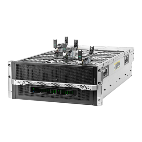
HP 7502 Switch Chassis (JD242C)
Purpose: The document is intended for use by end-of-life recyclers or treatment facilities. It provides the basic
instructions for the disassembly of HP products to remove components and materials requiring selective treatment, as
defined by EU directive 2002/96/EC, Waste Electrical and Electronic Equipment (WEEE).
1.0 Items Requiring Selective Treatment
1.1 Items listed below are classified as requiring selective treatment.
1.2 Enter the quantity of items contained within the product which require selective treatment in the right column, as
applicable.
Item Description Notes
Quantity
of items
included
in
product
Printed Circuit Boards (PCB) or Printed Circuit
Assemblies (PCA) With a surface greater than 10 sq cm
1
Batteries All types including standard alkaline and lithium
coin or button style batteries 0
Mercury-containing components For example, mercury in lamps, display
backlights, scanner lamps, switches, batteries
0
Liquid Crystal Displays (LCD) with a surface
greater than 100 sq cm Includes background illuminated displays with
gas discharge lamps 0
Cathode Ray Tubes (CRT) 0
Capacitors / condensers (Containing PCB/PCT) 0
Electrolytic Capacitors / Condensers measuring
greater than 2.5 cm in diameter or height 0
External electrical cables and cords 0
Gas Discharge Lamps 0
Plastics containing Brominated Flame
Retardants weighing > 25 grams (not including
PCBs or PCAs already listed as a separate item
above)
0
Components and parts containing toner and ink,
including liquids, semi-liquids (gel/paste) and
toner
Include the cartridges, print heads, tubes, vent
chambers, and service stations. 0
EL-MF877-00 Page 2
Template Revision B
Components and waste containing asbestos 0
Components, parts and materials containing
refractory ceramic fibers 0
Components, parts and materials containing
radioactive substances 0
2.0 Tools Required
List the type and size of the tools that would typically be used to disassemble the product to a point where
components and materials requiring selective treatment can be removed.
Tool Description Tool Size (if
applicable)
Screw driver 2#
3.0 Product Disassembly Process
3.1 List the basic steps that should typically be followed to remove components and materials requiring selective
treatment:
3.1.1 Guidance of treatments to the product:
Figure 1 Front of HP 7502
EL-MF877-00 Page 3
Template Revision B
Figure 2 Rear of HP 7502
1. Unscrew the screws on mounting angle 2, and then remove mounting angle 2;
2. Unscrew the screws on cabling rack 3, and then remove cabling rack 3 from mounting angle 2;
3. Unscrew the screws on front panel 4, and then remove front panel 4;
4. Unscrew the screws on front panel 5, and then remove front panel 5;
5. Unscrew the screws on blank panel 6, and then remove blank panel 6;
6. Unscrew the screws on power supply module 7, and then remove power supply module 7;
7. Unscrew the screws on blank panel 8, and then remove blank panel 8;
8. Unscrew the screws on blank panel 9, and then remove blank panel 9;
9. Unscrew the screws on fan module 10, and then remove fan module 10;
10. Remove film 11;
11. Unscrew the screws on rear cover plate 11, and then remove rear cover plate 11;
12. Unscrew the screws on protection cover 12, and then remove protection cover 12;
13. Unscrew the screws on protection box 13, and then remove protection box 13;
14. Unscrew the screws on rear cover plate 14, and then remove rear cover plate 14;
15. Unscrew the screws on PCB 15, and then remove PCB 15;
16. Remove all of the labels;
17. Remove all of shielding fingers.
3.1.2 Guidance of treatments to module 4:
Figure 3 Treatments to module 4
1. Unscrew the screws on PCB 4-2, and then remove PCB 4-2;
2. Remove shielding finger 4-3 from front panel 4-1;
3. Remove conductive foam 4-4 from front panel 4-1;
EL-MF877-00 Page 4
Template Revision B
4. Remove film 4-5 from front panel 4-1.
3.1.3 Guidance of treatments to module 5:
Figure 4 Treatments to module 5
1. Unscrew the screws on PCB 5-2, and then remove PCB 5-2;
2. Remove shielding finger 5-3 from front panel 5-1;
3. Remove film 5-4 from front panel 5-1.
3.1.4 Guidance of treatments to blank panel 6:
Figure 5 Treatments to blank panel 6
1. Remove shielding finger 6-2 from blank panel 6-1;
2. Remove film 6-3 from blank panel 6-1.
3.1.5 Guidance of treatments to blank panel 8
EL-MF877-00 Page 5
Template Revision B
Figure 6 Treatments to blank panel 8
1. Remove shielding finger 8-2 from blank panel 8-1.
3.1.6 Guidance of treatments to blank panel 9
Figure 7 Treatments to blank panel 9
1. Remove film 9-2 from blank panel 9-1;
2. Remove shielding finger 9-3 from blank panel 9-1.
3.1.7 Guidance of treatments to fan module 10
EL-MF877-00 Page 6
Template Revision B
Figure 8 Treatments to fan module 10
1. Remove the three fans 10-2 from fan frame 10-1;
2. Remove plug 10-3 from fan frame 10-1;
3. Remove the four wire mounts 10-4 from fan frame 10-1;
4. Unscrew the screws on PCB 10-5, and then remove PCB 10-5;
5. Remove shielding finger 10-6 from fan frame 10-1;
6. Unscrew the screws on handle 10-7, and then remove handle 10-7;
7. Remove film 10-8 from fan frame 10-1.
3.2 Material of the facility built
Facility Components Material Weight
(g) Weight
percentage Selective treatment for
materials and components Details
1 Fe 10411
50.46% Fe recycling
2 Fe 278
1.34% Fe recycling
3 ABS 22 0.10% Pla recycling
4
4-1 AL 767 3.71% Al recycling
4-2 Complex PWB 519 2.51% The surface of PCB is
greater than 10
square centimeters
5
5-1 Fe 1487 7.20% Fe recycling
5-2 Complex PWB 1000 4.84% The surface of PCB is
greater than 10
square centimeters
6
6-1 Fe 303 1.46% Fe recycling
7 Complex
PWB+Fe 2600 12.6% 1. Containing
brominated flame
retardants ;
2. The surface of
PCB is greater
than 10 square
centimeters;
3. Electrolyte
Fe recycling
EL-MF877-00 Page 7
Template Revision B
capacitor height
is more than 25
mm.
8
8-1 Fe 122 0.59% Fe recycling
9
9-1 Fe 156 0.75% Fe recycling
10
10-1 Fe 431 2.08% Fe recycling
10-2 Pla 98*3 1.42% Pla recycling
10-5 Complex PWB 35 0.16% The surface of PCB is
greater than 10
square centimeters
14 Fe 798 3.86% Fe recycling
15 Complex PWB 725 3.51% The surface of PCB is
greater than 10
square centimeters
cables 0404A068
04042967
0404A07J
04041104
Cu, Pla 682 3.30% 1. Containing
brominated
flame retardants
2. 04041104 is
external cables
Cu、Pla
recycling
4. Revised record
Date Version Author Modify content
2015.06.26 V0 Liao
Wenqing Initial version

Other HP Chassis manuals

HP MSR4060 Assembly instructions

HP

HP MSR4060 Assembly instructions

HP A7503-S Assembly instructions

HP

HP A7503-S Assembly instructions

HP FF 12916E Assembly instructions

HP

HP FF 12916E Assembly instructions

HP Moonshot 1500 Operating and safety instructions

HP

HP Moonshot 1500 Operating and safety instructions

HP apollo 4510 gen9 Operating and safety instructions

HP

HP apollo 4510 gen9 Operating and safety instructions

HP ProLiant s6500 User manual

HP

HP ProLiant s6500 User manual

HP A10504 Assembly instructions

HP

HP A10504 Assembly instructions

HP Apollo 4510 Gen10 Manual

HP

HP Apollo 4510 Gen10 Manual

HP BL685c - ProLiant - 4 GB RAM Programming manual

HP

HP BL685c - ProLiant - 4 GB RAM Programming manual

HP ProLiant s6500 User instructions

HP

HP ProLiant s6500 User instructions

HP Apollo a6000 Operating and safety instructions

HP

HP Apollo a6000 Operating and safety instructions

HP 7506 Assembly instructions

HP

HP 7506 Assembly instructions

HP MSA 2040 Guide

HP

HP MSA 2040 Guide

HP Apollo a6000 Operating and safety instructions

HP

HP Apollo a6000 Operating and safety instructions

HP A9508-V Assembly instructions

HP

HP A9508-V Assembly instructions

HP StorageWorks P2000 Guide

HP

HP StorageWorks P2000 Guide

HP A-F5000 Assembly instructions

HP

HP A-F5000 Assembly instructions

HP A10500 Series User manual

HP

HP A10500 Series User manual

Popular Chassis manuals by other brands

AIC RSC-2ETS user manual

AIC

AIC RSC-2ETS user manual

Keysight PXIe Series Firmware Guide

Keysight

Keysight PXIe Series Firmware Guide

Symantec NetBackup 5000 Replacement guide

Symantec

Symantec NetBackup 5000 Replacement guide

iStarUSA D-200L-T Product Quick Guide

iStarUSA

iStarUSA D-200L-T Product Quick Guide

BitFenix phenom mini-itx Quick installaion guide

BitFenix

BitFenix phenom mini-itx Quick installaion guide

Overland Storage SnapExpansion XSR Replacement instructions

Overland Storage

Overland Storage SnapExpansion XSR Replacement instructions

Supero SC836A-R1200B SC836E1-R800BSC836E1-R800V user manual

Supero

Supero SC836A-R1200B SC836E1-R800BSC836E1-R800V user manual

Cisco Nexus 7018 manual

Cisco

Cisco Nexus 7018 manual

iStarUSA D-300L Product Quick Guide

iStarUSA

iStarUSA D-300L Product Quick Guide

SilverStone CS351 manual

SilverStone

SilverStone CS351 manual

VIA Technologies AMOS-5000 user manual

VIA Technologies

VIA Technologies AMOS-5000 user manual

National Instruments PXIe-8238 Getting started

National Instruments

National Instruments PXIe-8238 Getting started

Cisco ONS 15454 manual

Cisco

Cisco ONS 15454 manual

Challenger TG9300C Operator's manual

Challenger

Challenger TG9300C Operator's manual

Leckey Hi-low Chassis User instructions

Leckey

Leckey Hi-low Chassis User instructions

Pickering 60-103D quick start guide

Pickering

Pickering 60-103D quick start guide

Transition Networks E-MCC-01 installation guide

Transition Networks

Transition Networks E-MCC-01 installation guide

Enterasys Matrix N7 7C107 Hardware installation guide

Enterasys

Enterasys Matrix N7 7C107 Hardware installation guide

manuals.online logo
manuals.online logoBrands
  • About & Mission
  • Contact us
  • Privacy Policy
  • Terms and Conditions

Copyright 2025 Manuals.Online. All Rights Reserved.