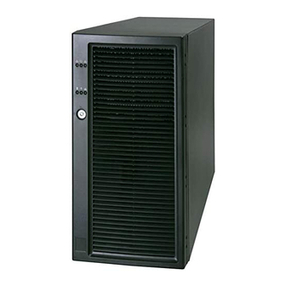
OSS OSS-PCIE-4UV-5-1 User manual

4U Value 5-Slot Chassis Gen4 User Manual
SKU: OSS-PCIE-4UV-5-1
www.onestopsystems.com
4U Value Gen4 5-Slot
5 PCIe (4.0 x16) Slot Expansion System

One Stop Systems
OSS-PCIe4-4UV-5 2
Table of Contents
Preface.................................................................................................................................................................................... 6
Advisories ....................................................................................................................................................................................................... 6
Safety Instructions.......................................................................................................................................................................................... 7
Protecting Against Electrostatic Discharge ..................................................................................................................................................... 8
1Introduction................................................................................................................................................................... 9
1.1 General Specifications ......................................................................................................................................................................... 9
1.2 Features............................................................................................................................................................................................. 10
1.3 Block Diagram.................................................................................................................................................................................... 10
1.3.1 Enclosure...................................................................................................................................................................................... 10
1.3.2 Backplane ..................................................................................................................................................................................... 10
1.3.3 Host and backplane ...................................................................................................................................................................... 11
1.4 Supported Configuration ................................................................................................................................................................... 11
1.4.1 Model 1 ........................................................................................................................................................................................ 11
1.4.2 Model 2 ........................................................................................................................................................................................ 12
1.5 PCIe Card / GPU Configuration..................................................................................................................................................... 13
1.6Main Components ............................................................................................................................................................................. 15
1.7 Parts Overview................................................................................................................................................................................... 15
1.8 Pre-Installation Information .............................................................................................................................................................. 17
1.9 Tools Required for Installation........................................................................................................................................................... 17
1.10 Items List ...................................................................................................................................................................................... 17
2Hardware Set-up / Installation ......................................................................................................................................18
2.1 Installation-Procedures Overview...................................................................................................................................................... 18
2.2 Before you Begin ............................................................................................................................................................................... 19
2.3 Remove Top Cover............................................................................................................................................................................. 19
2.4 Install Target Card.............................................................................................................................................................................. 20
2.5 Install Host Card................................................................................................................................................................................. 20
2.5.1 Host Card Configuration .............................................................................................................................................................. 20
2.5.2 Target Card Configuration ............................................................................................................................................................ 21
2.6 Connect Link Cables........................................................................................................................................................................... 23
2.6.1 x16 Configuration: FOUR cables ................................................................................................................................................... 23
2.6.2 x8 Configuration: TWO cables ...................................................................................................................................................... 24
2.6.3 x4 Configuration: ONE cable......................................................................................................................................................... 25
2.6.4 Disconnecting the cable ............................................................................................................................................................... 26
3Applying Power Correctly..............................................................................................................................................27
3.1 Connect Power Cord.......................................................................................................................................................................... 27
3.2 Connecting to electrical outlet........................................................................................................................................................... 28
3.3Power ON the Host Computer ........................................................................................................................................................... 28

One Stop Systems
OSS-PCIe4-4UV-5 3
3.4 Power ON the Expansion Unit ........................................................................................................................................................... 29
4Hardware Check............................................................................................................................................................30
4.1 Verify LINK ......................................................................................................................................................................................... 30
4.2 LED Indicators per Configuration ....................................................................................................................................................... 30
4.2.1 x16 Configuration LEDs................................................................................................................................................................. 30
4.2.2 x8 Configuration LEDs (Two Cables) ............................................................................................................................................. 31
4.2.3 x4 Configuration LEDs (One Cable)............................................................................................................................................... 33
4.3 Re-install Top Cover........................................................................................................................................................................... 35
4.4 Front LEDs Status Indicator................................................................................................................................................................ 35
4.5 Power Supply LED Indicator............................................................................................................................................................... 35
5Software Installation.....................................................................................................................................................36
6Verify HIB Device ..........................................................................................................................................................37
6.1 Linux OS ............................................................................................................................................................................................. 37
6.2 Windows 10 / Server ......................................................................................................................................................................... 41
7Verify Expansion Backplane ..........................................................................................................................................43
7.1 Linux .................................................................................................................................................................................................. 43
7.1.1 Check and Verify PCIe cards ........................................................................................................................................................ 45
7.2 Windows............................................................................................................................................................................................ 47
7.2.1 Check PCIe cards on Windows...................................................................................................................................................... 49
8PCIe card Installation ....................................................................................................................................................52
8.1 Power Down System.......................................................................................................................................................................... 52
8.2 Open PCIe Expansion Chassis............................................................................................................................................................ 52
8.3 Installation of GPU............................................................................................................................................................................. 53
8.3.1 Before you begin .......................................................................................................................................................................... 53
8.3.2 Install GPU cards .......................................................................................................................................................................... 54
8.3.3 Connect Aux Power Cable ............................................................................................................................................................ 56
8.3.4 Auxiliary Cable Management ....................................................................................................................................................... 56
8.4 Re-install top cover............................................................................................................................................................................ 57
8.5 System Power UP............................................................................................................................................................................... 57
9PCIe HW Verification .....................................................................................................................................................58
9.1 Verify PCIe Hardware........................................................................................................................................................................ 58
9.1.1 Target SLOT LINK LED ................................................................................................................................................................... 58
9.1.2 Slot LINK LEDs and AUX LED ......................................................................................................................................................... 58
9.1.3 Slot LED Status indicators ............................................................................................................................................................. 58
9.2 Check PCIe cards on Windows OS (i.e. Server) ............................................................................................................................. 59
9.3 Check PCIe cards on Linux OS ............................................................................................................................................................ 59
9.4 Check PCIe cards on Mac OS.............................................................................................................................................................. 59
10 General & Other Technical Information.........................................................................................................................60
10.1 Board LEDs ................................................................................................................................................................................... 60

One Stop Systems
OSS-PCIe4-4UV-5 4
10.2 PCIe Slot Type............................................................................................................................................................................... 61
10.3 Force Power ON ........................................................................................................................................................................... 61
10.4 Power Cords ................................................................................................................................................................................. 62
10.4.1 Specifications ............................................................................................................................................................................... 62
10.4.2 Power cord socket and voltage tables world standards ............................................................................................................... 62
10.5 Power Supply................................................................................................................................................................................ 63
10.5.1 Removing a hot-swap ac power supply ........................................................................................................................................ 63
10.5.2 Specifications ............................................................................................................................................................................... 64
10.5.3 LED Indicator ................................................................................................................................................................................ 65
10.6 Fan................................................................................................................................................................................................ 66
10.6.1 Fan Specifications......................................................................................................................................................................... 66
10.7 Auxiliary power cables.................................................................................................................................................................. 67
10.7.1 Aux power cable installation ........................................................................................................................................................ 68
10.7.2 Pin Outs........................................................................................................................................................................................ 69
10.7.3 Using the Auxiliary Power Cable.................................................................................................................................................. 71
10.8 Expansion System Power Consumption ....................................................................................................................................... 73
10.8.1 Power consumption breakdown per hardware............................................................................................................................ 73
11 Fan Controller ...............................................................................................................................................................74
11.1 Specifications ............................................................................................................................................................................... 75
12 Troubleshooting............................................................................................................................................................76
12.1 Locating the Problem ................................................................................................................................................................... 76
12.2 My Computer Cannot Find the PCIe Expansion System................................................................................................................ 76
12.3 My Computer Hangs During Power Up ........................................................................................................................................ 76
12.4 My PCIe Card Doesn’t Work ......................................................................................................................................................... 77
12.5 Support for 3PrdP Party PCIe Cards.............................................................................................................................................. 77
12.6 System board fails to power UP ................................................................................................................................................... 79
12.7 PCIe Upstream and Downstream Ports are not detected............................................................................................................. 79
12.8 Expansion System fails to turn ON ............................................................................................................................................... 80
13 Rackslide Installation ....................................................................................................................................................81
14 Enclosure Dimensions ...................................................................................................................................................83
15 Rackslide Mounting Position .........................................................................................................................................84
16 Frequently Asked Questions (FAQ) ................................................................................................................................85
17 Contacting Technical Support ........................................................................................................................................87
18 Third Party Hardware and Software Support Policy.......................................................................................................87
19 Returning Merchandise to One Stop Systems ................................................................................................................88
20 Shipping / transporting the unit ....................................................................................................................................88
21 APPENDIX A Compliance.............................................................................................................................................89
FCC ............................................................................................................................................................................................................... 89
CE ................................................................................................................................................................................................................. 89

One Stop Systems
OSS-PCIe4-4UV-5 5

One Stop Systems
OSS-PCIe4-4UV-5 6
Preface
Advisories
Five types of advisories are used throughout this manual to provide helpful information, or to alert you to the potential for hardware damage
or personal injury.
Disclaimer: We have attempted to identify most situations that may pose a danger, warning, or caution condition in this manual. However, One
Stop Systems does not claim to have covered all situations that might require the use of a Caution, Warning, or Danger indicator.

One Stop Systems
OSS-PCIe4-4UV-5 7
Safety Instructions
Always use caution when servicing any electrical component. Before handling the One Stop Systems Expansion chassis, read the following
instructions and safety guidelines to prevent damage to the product and to ensure your own personal safety. Refer to the “Advisories” section
for advisory conventions used in this manual, including the distinction between Danger, Warning, Caution, Important, and Note.
Always use caution when handling/operating the computer. Only qualified, experienced, authorized electronics personnel should access the
interior of the computer and expansion chassis.
WARNING
Never modify or remove the radio frequency interference shielding from your workstation or expansion unit. To do so may
cause your installation to produce emissions that could interfere with other electronic equipment in the area of your
system.
When Working Inside a Computer
Before taking covers off a computer, perform the following steps:
Turn off the computer and any peripheral devices.
Disconnect the computer and peripheral power cords from their AC outlets or inlets in order to prevent electric shock or system board damage.
In addition, take note of these safety guidelines when appropriate:
To help avoid possible damage to systems boards, wait five seconds after turning off the computer before removing a component,
removing a system board, or disconnecting a peripheral device from the computer.
When you disconnect a cable, pull on its connector or on its strain-relief loop, not on the cable itself. Some cables have a connector
with locking tabs. If you are disconnecting this type of cable, press in on the locking tabs before disconnecting the cable. As you pull
connectors apart, keep them evenly aligned to avoid bending any connector pins. Also, before connecting a cable, make sure both
connectors are correctly oriented and aligned.
CAUTION
Do not attempt to service the system yourself except as explained in this manual. Follow installation instructions closely.

One Stop Systems
OSS-PCIe4-4UV-5 8
Protecting Against Electrostatic Discharge
Electrostatic Discharge (ESD) Warning
Electrostatic Discharge (ESD) is the enemy of semiconductor devices. You should always take precautions to eliminate any
electrostatic charge from your body and clothing before touching any semiconductor device or card by using an
electrostatic wrist strap and/or rubber mat.
Static electricity can harm system boards. Perform service at an ESD workstation and follow proper ESD procedures to reduce the risk of
damage to components. One Stop Systems strongly encourages you to follow proper ESD procedures, which can include wrist straps and
smocks, when servicing equipment.
You can also take the following steps to prevent damage from electrostatic discharge (ESD):
When unpacking a static-sensitive component from its shipping carton, do not remove the component’s anti-static packaging material until you
are ready to install the component in a computer. Just before unwrapping the anti-static packaging, be sure you are at an ESD workstation or
are grounded.
When transporting a sensitive component, first place it in an anti-static container or packaging.
Handle all sensitive components at an ESD workstation. If possible, use anti-static floor pads and workbench pads.
Handle components and boards with care. Do not touch the components or contacts on a board. Hold a board by its edges or by its metal
mounting bracket.

One Stop Systems
OSS-PCIe4-4UV-5 9
1 Introduction
1.1 General Specifications
This 5-slot rackmount expansion platform provides PCIE expansion at a value price. The 4UV supports ONE PCIe 4.0 x16 host connection to 5
PCIe 4.0 x16 slots from 1m to 2m away from the host server. The system supports 5 full-length PCIe add-in cards (AICs) such as GPU card,
NVME flash and industrial I/O. Two fan choices allow for high-power add-in card cooling up to 100W per AIC or a set-and-forget manual speed
control using PWM fans when lower power AICs operation are required. Two 2000W power supplies provide redundant hot-swap system
power.
Item
Description
Host Card:
The system includes two PCIe 4.0x16 adapter cards: One host card & target card for connecting the accelerator to
any server.
HIB616-x16 Host/Target Interface cards
PCIe Switch 88032
Half Height, half length, single slot x16 PCIe add-in card form factor
PCIe4 x16 physical card edge connector (256Gb/s)
Backplane:
Two OSS-PCIe4-BP-5X16 (522 board)
- PCIe switch 88096
- PCIe 3 5-slot expansion backplane
The 5-slot integrated system includes:
- One HIB616x16 PCIe card
- Four (4) PCIe4 x16 double-width slots and One x16 single-width slot
Enclosure:
-Supports up t o 5 full-height, full-length PCIe slots plus 1 cable interface
-Supports extended height cards and top GPU power cables.
-Black medium texture liquid paint finish with optional OEM logo area.
-Power and Fan status bi-color LED panel
- Tool-less rack slides included
Dimensions:
19" W x 7" H x 17.7" D
Weight:
30.0 lbs without the baseboards (522) or add-in cards
PCI Express Bus Spec.
Revision 4.0
Interconnect Bandwidth:
256Gb/s
Cooling:
Three 120mm x 38mm fans mounted to the front bezel of the chassis
Two standard fan options available:
High-Capacity Fans:
-250CFM fixed-speed fans
-Fan monitoring via front panel LED
Variable Speed PWM Fans (optional):
-250CFM PWM controlled fans
-Set and forget PWM speed control module internal to the enclosure
Power Supply:
Dual load-sharing power supplies pluggable from the rear of the chassis:
- Two 2000W 80Plus Titanium efficiency power supplies
- Two integrated 90-264VAC, AC inputs (one in each supply)
100-140VAC at 1000W 200-240VAC at 2000W
- Power supplies can provide up to 4000W non-redundant total power to the system
- Supplies are redundant hot-swap when system power requirements are under 2000W total
Aux Power:
- An array of 8 EPS12V AUX power connectors available for high-power cards
MTBF:
53,000 hours
Operating Environment:
0-35°C 10-90% relative humidity 0-10,000 feet above sea level
Storage Environment:
-40 to 85°C 5-96% relative humidity 0-50,000 feet above sea level
Operating Systems:
Microsoft Windows Operating Systemsand Linux base OS
Agency Compliance
Agency Certifications (testing pending)
FCC Class A
CE Safety & Emissions
UL, cUL
RoHS2
Warranty:
1 Year Return to Factory. Extended Warranty is available and sold separately. Upon purchased of a new unit you
can buy an extended warranty.

One Stop Systems
OSS-PCIe4-4UV-5 10
1.2 Features
4U rackmount design
5 PCIe 4.0 x16 expansion slots
One PCIe 4.0 x16 host connections
Four x16 mini-SAS HD PCIe cables
PWM fan options
Two 2000W load-sharing power supplies
AUX power connectors for high power AICs
1.3 Block Diagram
1.3.1 Enclosure
1.3.2 Backplane

One Stop Systems
OSS-PCIe4-4UV-5 11
1.3.3 Host and backplane
1.4 Supported Configuration
1.4.1 Model 1
By default, the expansion unit is shipped out from the manufacturer with the expansion backplane mounted closest to the power supply.
The expansion unit is attached to one host server / computer.
A single Host Cable adapter card is installed in the host computer.
One Target card in the expansion backplane..

One Stop Systems
OSS-PCIe4-4UV-5 12
1.4.2 Model 2
The location of the expansion backplane is mounted on the far right-end side in the enclosure.

One Stop Systems
OSS-PCIe4-4UV-5 13
1.5 PCIe Card / GPU Configuration
The 4UV Gen4 5-slot expansion backplane will support up to five full-length single-wide GPUs or four full-length double-wide GPUs.
The GPUs are installed on the PCIe x16 Gen4 PCIe slot.
Single-wide GPU configuration: You can fit 5 single-wide GPUs on the expansion backplane
Double-wide GPU Configuration: The Gen4 expansion backplane can only accommodate four double-wide GPUs.

One Stop Systems
OSS-PCIe4-4UV-5 14
Combo GPU Configuration: You can install a combination of double-wide GPUs and single-wide GPUs.
Combo GPU Config1
Combo GPU Config2
It is strictly recommended to install the same brand / maker of GPUs.

One Stop Systems
OSS-PCIe4-4UV-5 15
1.6 Main Components
The 4U Value GPU Accelerator Systemic composed of following major components
1. Single5-slot Backplanes
2. One Target Card : PCIe 4.0 x16
3. One Host Card: PCIe 4.0 x16
4. Four SFF-8644 PCIe Gen4 PCIe Cables
5. One or Two 2000W Power Supplies
6. Three 120mm x 38mm Fans (250cfm)
1.7 Parts Overview

One Stop Systems
OSS-PCIe4-4UV-5 16

One Stop Systems
OSS-PCIe4-4UV-5 17
1.8 Pre-Installation Information
Before using the One Stop Systems expansion unit, you should perform the following steps:
Inventory the shipping carton contents for all of the required parts
Gather all of the necessary tools required for installation
Read this manual
1.9 Tools Required for Installation
To complete the installation of the product you will need a Phillips-head screwdriver and ESD wrist strap to prevent electrostatic discharge.
1.10 Items List
Item
Qty
Description
1
2
Full-height PCI Express Adapter Cards
2
4
SFF –8644 x16 PCIe Gen4 cable
3
2
U.S. Standard 125V or 250V
4
1 set
Rackslide and Kit (Optional)

One Stop Systems
OSS-PCIe4-4UV-5 18
2 Hardware Set-up / Installation
The following steps will guide you through the installation of your One Stop Systems expansion system
CAUTION
Hardware installation shall be performed only by qualified service personnel per UL and IEC 60950-1.
Electrostatic Discharge (ESD) Warning
All PCI cards are susceptible to electrostatic discharge. When moving PCI cards, it is best to carry the cards in anti-static
packaging. If you need to set a PCIe card down, be sure to place it inside or on top of an anti-static surface. For more
information, see “Protecting Against Electrostatic Discharge” in the Preface.
WARNING
High voltages are present inside the expansion chassis when the unit’s power cord is plugged into an electrical outlet.
Disconnect the power cord from the AC outlet before removing the enclosure cover. Turning the system power off at the
power on/off switch does not remove power to components. High voltage is still present.
CAUTION
Before touching anything inside the enclosure, move to an ESD station and follow proper ESD procedures. Failure to do so
may result in electrostatic discharge, damaging the computer or its components. For more information, see “Protecting
Against Electrostatic Discharge” in the Preface.
2.1 Installation-Procedures Overview
Below is the concise version on how to set up the 4U Value GPU Accelerator System.
1. Open Enclosure: Section 2
2. Target Card Installation (If not installed): Section 2
3. Host Card Installation: Section 2
4. Link Cablse Installation: Section 2
5. Connecting Power: Section 3
6. Powering UP the Systems: Section 3
7. Hardware Check: Section 4
8. Re-install Top Cover: Section 4.3
9. Verify Installation (via Operating System): Section 6
10. GPU card or PCIe card Installation: Section 8
11. GPU or PCIe card Check or Verification: Section 9
When installing 3rd Party PCIe card, start with one card first to determine if there are any software and hardware issues or incompatibility
problems that may occur. This will help you in troubleshooting the problem more easily and efficiently. If everything works well and no
configuration issues, you can proceed with the installation of the remaining 3rd party PCIe cards.
Always refer to or read “3rd party manufacturer installation guide” for further instructions.

One Stop Systems
OSS-PCIe4-4UV-5 19
2.2 Before you Begin
The system’s power supply is auto-switching, it will automatically switch to match whatever source power you are using. The product is shipped
with a US/Canadian Standard, 125V or 250V power cord.
2.3 Remove Top Cover
Remove the five (5)mounting screws on top of the chassis. Slide the enclosure cover towards the front of the unit to disengage it from the
guides until it clears the back hold-down, and then lift the cover off.
Check inside the unit; make sure the “Target Adapter Card “is fully seated in the Upstream slot.

One Stop Systems
OSS-PCIe4-4UV-5 20
2.4 Install Target Card
By default the “Target card (OSS-PCIe-HIB616-x16)”is installed in the target slot / upstream slot of the expansion system.
Check the switches on the Target card, make sure it is configured to Target mode.See photo below for the Target mode switch
settings.
2.5 Install Host Card
Before installation, you must check the switches on the Host card. By default, all the switches on the Host card are set to OFF position (“Auto-
Negotiation” mode). You can leave the switches to default or manually set the switches (SW1 and SW2) on the card for the desired Host
operating mode. See “Host Card Configuration” section for more details. See photos below for host mode switch settings.
2.5.1 Host Card Configuration
By default, the Host adapter card is set to “Auto-Negotiation” mode. All switches are set to OFF position. The following are manual switch
settings on the Host card.
x16 Dip switch Settings:
SW1 #2 = ON; #5 =ON.
SW2 #1 = ON; #2 = ON
Table of contents
Other OSS Chassis manuals
Popular Chassis manuals by other brands
Supermicro
Supermicro SCE102 user manual
National Instruments
National Instruments cDAQ CALIBRATION PROCEDURE

Paradyne
Paradyne Hotwire 8774 user guide
Siemens
Siemens SINAMICS G130 operating instructions
Aurora
Aurora DXM G4 Series user guide
National Instruments
National Instruments PXIe-1092 CALIBRATION PROCEDURE
Chenbro
Chenbro SR209 Plus Series user manual

Intel
Intel H2000 Series Technical product specification
Allied Telesis
Allied Telesis AT-MCR1 specification
Sonnet
Sonnet Echo Express SEL user guide
National Instruments
National Instruments NI 9157 Operating instructions and specifications
F5
F5 ARX 6000 Hardware installation guide
