Alicat L Series User manual

OPERATING MANUAL
FOR LIQUID FLOW METERS
Models L · LB · LS · LBS

2 Introduction
Thank you for purchasing your liquid mass flow meter.
If you have any questions, or if something is not working as
expected, please contact us. We are eager to help you in any
way possible.
Contact Information
World Headquarters,
Tucson, Arizona, USA
info@alicat.com
alicat.com
7641 N Business Park Dr.,
Tucson, AZ 85743 USA
+1 888-290-6060
Europe
Geograaf 24
6921 EW Duiven
The Netherlands
+31 (0) 26 203.1651
China & SE Asia
info-cn@alicat.com
alicat.com.cn
2nd Floor, Block 63, No. 421,
Hong Cao Rd,
Shanghai 200233
PRC
+86-21-60407398 ext. 801
India
india@alicat.com
Halma India Pvt. Ltd.
Plot No . A-147, Road No. 24,
Next to Spraytech Circle
opp. Metropolitan Company,
Wagle Industrial Estate
Thane-West
Mahārāshtra 400 604
+91 022-41248010
Recalibrate your mass flow meter every year.
Annual calibration is necessary to ensure the accuracy of
readings, and extend the Limited Lifetime Warranty. Fill out
the Service Request Form at alicat.com/service,or contact us
directly when it is time for recalibration.
For devices ordered with CSA, ATEX, ISO 17025, or other certi-
fications, please visit alicat.com/certifications. For information
about our limited lifetime warranty, visit alicat.com/warranty.
Serial #:
Next Calibration:
This device comes with a NIST-
traceable calibration certificate.
This device conforms to the European
Union’s Restriction of Use of Hazardous
Substances in Electrical and Electronic
Equipment (RoHS) Directive 2011/65/EU.
This device complies with the requirements
of the Low Voltage Directive 2014/35/
EU and the EMC Directive 2014/30/EU
and carries the CE Marking accordingly.
This device complies with the
requirements of the European Union’s
Waste Electrical & Electronic Equipment
(WEEE) Directive 2002/96/EC
DOC-MANUAL-L Rev 1, 2021.05.26
L-1LPM
LB-1LPM

2021.05.26 REV. LIQUID FLOW METER OPERATING MANUAL 3
Introduction
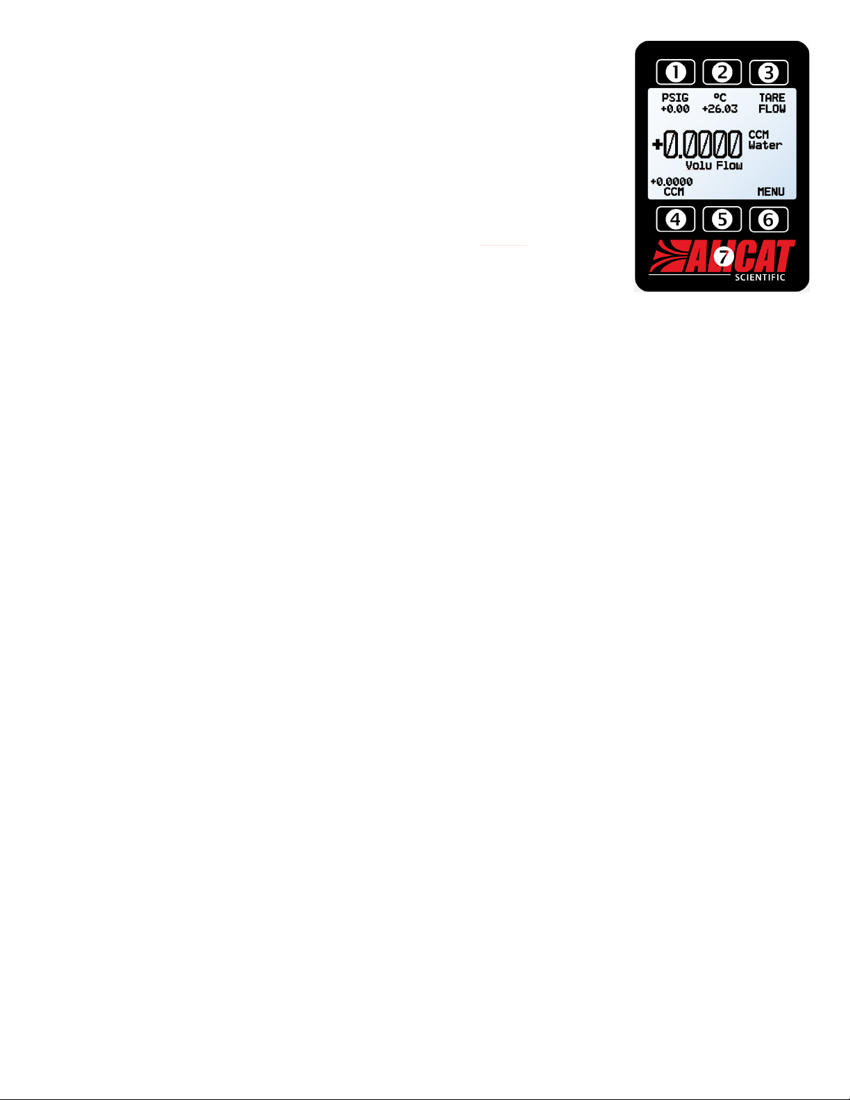
Your new flow meter has a variety of innovative features:
• 1000 readings per second guarantees high resolution
data, page 9.
•
Monitor live pressure and temperature during flow
measurement, page 10.
•
Backlit display with adjustable contrast is easy to read
even in direct sunlight. In dimly lit areas, press the logo
to turn on the backlight, page 13.
•
Connection to a computer for control and data logging
to capture all pressure data for logging and analysis,
page 14.
This manual covers the following instruments:
• L-Series: liquid flow meters
• LB-Series: portable liquid flow meters
• LS-Series: anti-corrosive liquid flow meters
• LBS-Series: portable anti-corrosive flow meters
Using Laminar Liquid Flow Devices
THE DEVICE IS ONLY CONFIGURED FOR ONE
TYPE OF LIQUID, AND WILL ONLY FUNCTION
PROPERLY WHEN USING THAT ONE LIQUID.
By default, liquid devices are configured only for use with
pure water, such as distilled, de-ionized, Type I (Ultrapure),
Type II, and Type III. If a device is used for any liquid other
than the liquid it was specifically engineered for, readings
will be incorrect
Minimize contaminants and liquid variations. For water
devices, DO NOT use tap water or water with any biological
components, minerals, or oils. Any of these substances
will aect the viscosity of the liquid, leading to inaccurate
flow measurements. More importantly, these impurities
will quickly build up in the laminar flow zone, cause
corrosion, and degrade the measurement accuracy
of the device.
For support or questions regarding the use or operation
of this device, please contact us using the information
on page 2.
Alicat oers countless combinations of device sizes, acces-
sories, connections, and configurations. These custom
solutions are oered to meet a variety of application chal-
lenges brought forth by users pushing the boundaries of
our standard oerings.
If you have an idea for a new process or a challenging
application, contact Alicat for specialized engineering and
application support.
L-10LPM

4 Table of Contents
Contents
Introduction 3
Using Laminar Liquid Flow Devices 3
Quick Start Guide 5
Getting Started 6
Getting to Know Your Liquid Flow Meter 6
The Liquid Flow Meter Display 6
Status Messages 6
Mounting 6
Filters 6
Device Ports 7
Connecting Your Liquid Flow Meter 7
Operating Pressure 7
Bleed Ports 7
Power and Signal Connections 8
Analog Signals 9
Displaying Live Flow Data 10
Main Display 10
Taring Your Flow Meter 10
How to Tare 10
Option: Color TFT Display 10
Option: Collecting Totalized Flow Data 11
Device Information 11
Setup 12
Sensor Setup 12
Choosing Engineering Units 12
Flow and Pressure Averaging 12
Zero Band 12
Configuring Serial Communications 12
Unit ID 12
Modbus RTU Address 12
Baud Rate 12
Display Setup 13
Main Screen Options 13
Screen Lighting 13
Display Rotation 13
Advanced Setup 13
Serial Communication 14
Establishing Communication 14
Modbus RTU Communication 14
Serial Streaming vs Polling 14
Polling Mode 14
Taring 15
Collecting Flow Data 15
Quick Command Guide 16
Troubleshooting 17
Maintenance 18
Reference Information 19
Engineering Units 19
Pinouts 20
8-Pin Mini-DIN (Default) 20
Locking Industrial Connector Pinout 20
9-Pin D-Sub Connector Pinouts 21

2021.05.26 REV. LIQUID FLOW METER OPERATING MANUAL 5
Quick Start Guide
Setup
•
Connect your liquid flow meter. Ensure
that flow will pass through your device in the
same direction as the arrow on the flow body
(usually left to right).
•
Choose your engineering units. You can
choose the measurement units by selecting
MAIN MENU
→
SETUP
→
Sensor
→
Engineering
Units, see page 12 for more details.
Operation: Flow Verification
•
Monitor live volumetric flow, temperature,
and pressure readings. Readings are
updated and displayed on your device in
real time. See page 10.
•
(Optional) Capture totalized readings. The
totalizer option displays the total flow that
has passed through the device since the last
time the totalizer was reset. If your device
has a totalizer, press NEXT from the main
live data display to access the totalizer. See
page 11.
Connectors and Buttons
The diagram the right below represents a typical
configuration of a standard liquid flow meter.
Your liquid flow meter’s appearance and
connections may differ.
Backlight
The monochrome display comes equipped with
a backlight. To toggle the backlight power,
press the logo on the front of your device.
For optional color TFT displays, pressing this
button will turn off the display to conserve
power. See page 10.
Maintenance and Care
• Liquid flow meters require minimal cleaning
when flowing clean liquids. Read more on
page 18.
•
Calibrate your liquid flow meter annually.
To schedule a calibration, please contact
support (page 2).
A typical liquid flow meter.

6 Getting Started
Getting Started
Getting to Know Your Liquid Flow Meter
The Liquid Flow Meter Display
The figure to the right identifies the various features of the flow meter display.
Highlights pressure in the center of the device.
Highlights temperature in the center of the device.
Tares the device's flow measurement (page 10).
Highlights volumetric flow rate in the center of the device.
MENU enters the main menu system.
NEXT accesses the optional flow totalizer (page 11).
Toggles the backlight.
Status Messages
Status messages are shown to the right of the main readout number. In the example to the
right, the OVR message shows that the totalizer rolled over to zero.
ADC Analog-digital converter error
LCK Front display is locked
OVR Totalizer rolled over to zero
POV Pressure over range of device
TMF Totalizer missed out of range flow
TOV Temperature over range of device
VOV Volumetric flow over range of device
Mounting
Liquid flow meters do not require straight runs of pipe are required upstream or downstream. Most flow meter models
can be mounted in any position, including upside-down. All liquid flow meters use media-isolated sensors that must be
tared after changing orientation.
✓
Note: If air bubbles are continuously introduced to the flow upstream of the device, the device may be mounted up
side-down to prevent bubbles from being trapped in the pressure sensor ports. Tare the device after changing its position
or orientation.
!
Warning: If the device has been installed upside-down, avoid using the bleed screws as liquid may leak into the electronics
housing and cause permanent damage that is not covered by the warranty.
Filters
When pressure drop is not a concern, use in-line sintered filters to prevent large particulates from entering the flow body
of the meter. Suggested maximum particulate sizes are as follows:
• 20 microns for units with flow ranges ≤100 CCM.
• 40 microns for units with flow ranges >100 CCM.
✓ Note: Avoiding long runs of small-diameter tubing upstream or downstream of the device will reduce liquid hammer.
The main display. Note the button
behind the logo, which toggles the
device backlight.
The main display with an OVR
status message.

2021.05.26 REV. LIQUID FLOW METER OPERATING MANUAL 7
Device Ports
Your flow meter has been shipped with plastic plugs fitted into its ports. To lessen the
chance of contaminating the flow stream, do not remove these plugs until you are ready
to install the device.
Standard liquid flow meters have female inlet and outlet ports. VCR®-compatible and other
specialty fittings may have male connections.
• If you are using a fitting that does not have a face seal, use thread-sealing Teflon tape
to prevent leakage around the port threads, but do not wrap the first two threads
entering the device. This will minimize the possibility of getting tape into the flow stream
and clogging the laminar flow element.
• Face seal fittings do not need Teflon tape applied to the threads.
! Warning: It is not recommended to use pipe dopes or sealants on the process connections as
these compounds can cause permanent damage to the meter should they get into the flow
stream.
Connecting Your Liquid Flow Meter
Your flow meter can measure flow generated by positive pressure and/or suction. Connect
the meter so that the flow travels in the same direction as the flow arrow, usually from left
to right from the front of the device.
Operating Pressure
Maximum operating line pressure is 100 . If the line pressure is higher than 100 , use a pressure regulator upstream
to reduce the pressure. Maximum proof pressure is 200 ; above this pressure the device may be permanently damaged.
Although the meter’s operation is unidirectional, reversing the flow direction will not damage the device as long as the
maximum specified limits are not exceeded.
▲
Caution: Exceeding the maximum specified line pressure may cause permanent damage to the solid-state dierential
pressure transducer.
Bleed Ports
Liquid flow meters include bleed ports (8-32 Nylon tapped screw) on the front for the
removal of air bubbles.
Bleed both of the ports as follows:
1.
With the meter installed, gently loosen the upstream bleed port screw 1 to 2 turns,
or until liquid begins to leak from the threads. Do not remove the screw, as it
has pressure behind it, is very small, is easy to lose, and is delicate to rethread.
2. Gently tap the flow body to remove air bubbles (screwdriver handles work well).
This may not be visible or audible.
3.
Gently tighten the screw until the leakage stops, taking care not to crush the
nylon tip.
▲
Caution: If your device is mounted in an inverted position,
avoid using the bleed screws, as liquid may leak and cause
permanent damage.
A VCR®-compatible connection.
A VCO®-compatible connections.
5⁄64″ 8-32 Nylon-tipped
hex bleed screw
Loosen to bleed liquid,
but do not remove

8 Getting Started
Option: Charging Your Portable Meter
Portable meters’ batteries are partially charged before shipping. When fully charged, typical
battery life is 18 hours with a monochrome display, or 8 hours with a TFT color display.
Dimming the backlight will increase battery life. When the battery indicator displays it is
completely empty, about 15 minutes of battery life remain.
Charge the device using the supplied USB cable (micro-B to type A) or a similar cable.
Any USB outlet on a computer or portable power supply may be used, but charging will
be fastest (approximately 3.5 hours) when connected to the supplied 2.0 A power supply.
The red indicator LED on top of the device lights up to indicate that the unit is charging,
and turns o when the battery is charged.
Your meter may be used while it is charging. If the battery has been fully depleted, you may
need to charge the device for a full minute before the device can be turned on.
! Warning: The safe charging temperature range is 0–45°C (32–113°F). If internal sensors detect temperatures outside of
this range, the battery will not charge.
Power and Signal Connections
Power can be supplied to your meter through either the power jack or the multi-pin connector on top of your device.
✓
Note: Power requirements vary based on analog configuration. Please reference the associated specification sheet at
alicat.com/specs for power requirements.
Standard 8-Pin Mini-DIN Pinout
Pin Function
Not Connected Optional: 4–20 mA Primary Output Signal
Static 5.12 Vdc by default. Optional: Secondary Analog Output (4–20 mA, 0–5 Vdc, 1–5 Vdc, 0–10 Vdc) or Basic Alarm
Serial RS-232 RX / RS-485(−) input signal (receive)
Remote tare (ground to tare)
Serial RS-232 TX / RS-485(+) output signal (send)
0–5 Vdc Optional: 1–5 Vdc or 0–10 Vdc Output Signal
Power In (as described above)
Ground (common for power, digital communications, analog signals and alarms)
The above pinout is applicable to all devices with the Mini-DIN connector. The availability of dierent output signals depends on the options ordered.
Optional configurations are noted on the unit’s calibration sheet.
▲Caution: Do not connect power to pins 1 through 6, as permanent damage can occur. It is common to mistake pin 2 (5.12
Vdc Output) as the standard 0–5 Vdc analog output signal. Pin 2 is normally a constant 5.12 Vdc.
For more pinout configurations, see page 20.
The main display with battery
information and an active charging
indicator (the lightning bolt).
Male Connector: Cable
Female Connector: Device
1
4
5
68
7
3
2 1
4
5
6
87
3
2

2021.05.26 REV. LIQUID FLOW METER OPERATING MANUAL 9
Analog Signals
Primary Analog Output Signal
Most instruments include a primary analog output signal, which is linear over its entire range. For all analog output
configurations, the lowest output indicates zero flow, and highest indicates full-scale flow. Depending on the quality of
the grounding, a zero flow condition is approximately 0.010 Vdc.
For example, a 5 Vdc output from a 0–5 Vdc 100 CCM unit would indicate a flow of 100 CCM.
Using Ground to Tare
You can tare your meter remotely by momentarily grounding pin 4. When the switch is closed, the device will tare. Oper-
ation will resume when the switch is released. You can also tare with the front controls (page 10) or serial commands
(page 15).
Option: Secondary Analog Output Signal
The default 8-pin Mini-DIN connector places the secondary analog output on pin 2 for both voltage and current signals.
Your device’s secondary analog signal may dier from its primary output signal.
The calibration sheet that shipped with the device shows which output signals were ordered.
Option: 4–20 mA Current Output Signal
If your meter has a 4–20 mA current primary or secondary output signal, your flow meter will require 15–30 Vdc power.
▲
Caution: Do not connect 4–20 mA devices to “loop powered” systems, as this will damage portions of the circuitry beyond
repair and void the warranty. If you must interface with existing loop powered systems, always use a signal isolator and
a separate power supply.
Pin 8
Ground
Pin 4
Pin 4
Pin 8
Connect to tare

10 Getting Started
Displaying Live Flow Data
Main Display
The main display has three primary functions:
• Displaying live temperature, pressure, and flow data
• Taring the flow meter (below)
• Accessing the main menu (MENU) or the optional totalizer (NEXT) (page 11)
This screen displays live data for all flow parameters simultaneously. Live data is measured
1000 times per second and the LCD display is updated 10 times per second. The buttons
next to the measurements highlight their values in the center.
Taring Your Flow Meter
MENU →TARE FLOW or TARES
Taring is an important practice than ensures your liquid flow meter is providing its most accurate measurements. This
function gives the meter a zero reference for flow measurements. Gauge pressure can also be tared on all liquid devices.
How to Tare
Taring Flow
MENU →TARES →TARE FLOW
Flow tares should take place at the expected process pressure, with no flow. A message, “
ENSURE NO FLOW BEFORE
PRESSING TARE” will be displayed. Press TARE to complete the taring process.
Taring Pressure
MENU →TARES →TARE PRESS
After pressing TARE PRESS, the message, “PRESS TARE WHEN VENTED TO AMBIENT WITH NO FLOW”, followed by “CURRENT
PRESSURE OFFSET:” will be displayed.
When to Tare
• Before every new flow measurement cycle
• After significant changes in temperature or pressure
• After dropping or bumping the flow controller
• After changing the device’s orientation
Option: Color TFT Display
Instruments ordered with a color display are functionally the same as standard backlit monochrome instruments. The
color enables additional on-screen information.
Multi-Color Display Indicators
• GREEN: Parameter labels and adjustments associated with the button directly above or below the label.
• WHITE: Parameters operating under normal conditions.
• RED: Parameters with values exceeding 128% of the device’s specifications.
• YELLOW: Menu items ready to be selected. This color replaces the symbol (>) in selections on monochrome display.
✓ Note: Press the logo to turn o the color display backlight. The flow meter remains in operation while the backlight is o.
✓ Note: Color displays require an additional 40 mA when using a 12 Vdc power supply. All other device specifications from
your device’s specification sheet remain in eect.
The main display.

2021.05.26 REV. LIQUID FLOW METER OPERATING MANUAL 11
Option: Collecting Totalized Flow Data
MAIN DISPLAY →NEXT (totalizer menu)
The optional flow totalizer displays the total amount that has flowed through the instrument since its last reset, similar
to a gasoline pump.
• TOTAL/TIMER toggles between totalized flow and elapsed time as the highlighted parameter in the center.
•
LPM (or another measurement of volumetric flow) displays the live flow rate. Press to change engineering units
(page 12).
• V PEAK displays the maximum flow rate since the last reset. Press to select engineering units (page 12).
• RESET clears all totalized data and immediately resets the timer to zero.
• MENU enters the main menu.
Totalizer Rollover Functions
The totalizer will report a maximum of 7 digits. By default, the placement of the decimal is the same as the live flow rate.
The totalizer can be configured at the time of order for the following behaviors:
• Rollover (Default): Totalizer resumes counting from zero as soon as the maximum count has been reached.
• Freeze: Totalizer stops counting at max count, until it is reset manually.
• Error (Default): Displays OVR status message when maximum count has been reached; compatible with the rollover
and freeze functions.
The elapsed time counter has a maximum value of 9999:59:59 (h:m:s) (416 days, 16 hours). If flow is still being totalized
at that point, the timer freezes, regardless of the behavior chosen above for the totalized flow readings.
Device Information
The ABOUT menu (MENU →ABOUT) contains useful information for setup, configuration, and troubleshooting.
Basic Device Information
ABOUT →About Device
This includes information on the following:
• MODEL: Device model
• SERIAL NO: Serial number
• DATE MFG: Manufacturing date
• DATE CAL: Most-recent calibration date
• CAL BY: Initials of the person who calibrated the device
• SW: Firmware version
• Display SW (color displays only): Firmware version of the display
Device Full-Scale Ranges
ABOUT →Full Scale Ranges
This displays the maximum readable range of available flow and pressure readings. Most will include volumetric flow and
gauge pressure. Devices equipped with an optional barometer will also show barometric pressures.
Manufacturer Information
ABOUT →About Manufacturer
About Manufacturer usually includes:
• Manufacturer name
• Web address
• Phone number
• Email address

12 Setup
Setup
Sensor Setup
MENU →SETUP →Sensor
Choosing Engineering Units
SETUP →Sensor →Engineering Units
Changing device engineering units alters both the display and the data frame. Choose the parameter whose unit you
want to change, and then select your desired engineering unit, confirming the change on the last screen.
Flow and Pressure Averaging
SETUP →Sensor →Flow Averaging
SETUP →Sensor →Pressure Averaging
Averaging the flow over a longer time may be useful in smoothing fluctuating readings. This menu changes the time
constants of the geometric running averages for flow and pressure. These are changed independently via PRESS AVG and
FLOW AVG
in the averaging menu, which also displays the current settings. Values roughly correspond to the time constant
(in milliseconds) of the averaged values. Higher numbers generate a greater smoothing eect, to a maximum of 255 ms.
Zero Band
SETUP →Sensor →Zero Band
The zero band threshold is an amount of flow under which flow values are displayed as . The maximum zero band is
6.38%. For example, a 10-LPM meter with a zero band value of 0.25% would display as LPM for all readings below
0.025 LPM.
Configuring Serial Communications
MENU →SETUP →RS-232 Serial or RS-485 Serial
You can operate the flow meter remotely via its data connection for easy streaming and logging of all data. Before
connecting the flow meter to a computer, ensure that it is ready to communicate with your PC by checking the options
in this menu. For more on how to issue commands from a computer, see page 14.
Unit ID
SETUP →RS-232 Serial or RS-485 Serial →Unit ID
The unit ID is the identifier that a computer uses to distinguish your device from other, similar devices when it is connected
to a network. Using the unit ID letters A–Z, you can connect up to 26 devices to a computer at the same time via a single
port. This is called polling mode (page 14). Unit ID changes take eect when you select
SET
. If you select “
@
”
as the unit ID, the flow meter will enter streaming mode when you exit the menu (page 15).
Modbus RTU Address
SETUP →RS-232 Serial or RS-485 Serial →Modbus Address
The Modbus address is the identifier that a computer or programmable logic controller (PLC) uses to distinguish your
device from other devices when connected to a Modbus network. Values of 1–247 are available for use.
Baud Rate
SETUP →RS-232 Serial or RS-485 Serial →Baud Rate
Baud rate is the speed at which digital devices transfer information. The flow meter has a default baud rate of 19200
baud (bits per second). Your computer or software’s settings must match the flow meter’s baud rate. In the BAUD menu,
ensure that they match. Alternatively, you can change your computer’s baud rate in Windows® Device Manager. Baud
rate changes take eect once you press SET, but you may need to restart the software for it to recognize the change.

2021.05.26 REV. LIQUID FLOW METER OPERATING MANUAL 13
Display Setup
MENU →SETUP →Display
The options in the display setup menu adjust the contrast/brightness of the display and enable screen rotation.
Main Screen Options
SETUP →Display →MAIN Screen
Any Key Press changes what happens when any of the parameter buttons on the main display (page 10) are pressed
(pressure or temperature, for example). By default, these buttons highlight their measurement in the center of the display.
If this option is set to Show Actions Menu, an option to change that parameter’s engineering units will be shown, as well
as an option to highlight the parameter.
Screen Lighting
SETUP →Display →Screen Lighting
The options and wording in the screen lighting menu will vary for color displays.
•
On monochrome displays, press
LESS CONTRAST
or
MORE CONTRAST
to adjust the contrast levels and move the contrast
indicator left or right.
POWER UP Lit
or
Dark
toggles whether the backlight of the unit will be on when the device
powers on.
• On color displays, press DIMMER or BRIGHTER to adjust the brightness level and move the brightness indicator left or
right.
Display Rotation
SETUP →Display →Display Rotation
The device has the option of inverting (flipping) the screen, as configured in this menu.
Advanced Setup
MENU →SETUP →Advanced
The advanced setup menu contains settings and detailed information that are useful when troubleshooting with customer
support.
Factory Restore
SETUP →Advanced →Factory Restore
This will immediately take you to a confirmation screen. When troubleshooting, an applications engineer may recommend
doing a Factory Restore. If something is not acting as expected, please contact an applications engineer prior to doing
a Factory Restore.
Register Status
SETUP →Advanced →Register Status
The Register Status screen displays live values for the internal device registers. Many of these values can help an
applications engineer diagnose operational issues over the phone. Some register values clearly distinguish between
hardware and operational problems, which speeds up the troubleshooting process.
Edit Register and Device Properties
SETUP →Advanced →Edit Register and SETUP →Advanced →Device Properties
! Warning: Editing these settings may cause the device to become inoperable. Do not modify them without working with
customer support.

14 Serial Communication
Serial Communication
Connecting your device to a computer allows you to log the data that it generates. The device communicates digitally
through its communications connector and cable using a real or virtual port on your computer. This section of the
manual shows you how to operate the flow meter using ASCII commands.
Establishing Communication
After connecting your flow meter using a communications cable, you will need to establish serial communications through
a real or virtual port on your computer or programmable logic controller (PLC).
• If you have connected your deviceto a serial port, note its port number, which can be found in the Windows®
Device Manager program.
• If you have used a USB cable to connect your device to your computer, the computer in most cases will recognize
your device as a virtual port. If it does not, download the appropriateUSB device driver at alicat.com/drivers and
note the port number as found inWindows® Device Manager.
The meter will be configured with the following settings:
• Baud: 19200 (by default; others can be used if the computer, software, and meter are all set to the same rate)
• Data bits: 8
• Parity: none
• Stop bits: 1
• Flow control: none
Alicat’s Serial Terminal Application
Alicat’s Serial Terminal is a preconfigured program for serial communications that functions much like the older Windows®
HyperTerminal, with plain text in a command-line format.
Download Serial Terminal for free at alicat.com/drivers. Once downloaded, simply run SerialTerminal.exe. Enter the
port number to which your device is connected and the baud rate of the flow meter. The default baud rate is 19200, but
this is adjustable by entering the RS-232 Serial menu on your flow meter (page 12).
Modbus RTU Communication
For details on Modbus commands, please visit alicat.com/manuals for the Modbus operating bulletin.
Serial Streaming vs Polling
✓
Note: In what follows, indicates an ASCII carriage return (decimal 13, hexadecimal D). For many devices, this is the same
as pressing the Enter key. Serial commands are not case-sensitive.
Polling Mode
Your device was shipped in polling mode with a unit ID of A, unless requested otherwise. Polling the device returns a
single line of data each time you request it. To poll your device, simply enter its unit ID.
Poll the device: [unit ID]
Example: a(polls unit A)
You can change the unit ID of a polling device by typing:
Change the unit ID: [current unit ID]@=[desired unit ID]
Example: a@=b(changes unit A to unit B)
You can also do this via the device’s front panel menu (page 10). Valid unit IDs are letters A–Z, and up to 26 devices
may be connected at any time, as long as each unit ID is unique.

2021.05.26 REV. LIQUID FLOW METER OPERATING MANUAL 15
Streaming Mode
In streaming mode, your device automatically sends a line of live data at regular intervals. Only one unit on a port
may be in streaming mode at a time. To put your device into streaming mode, type:
Begin streaming: [unit ID]@=@
Example: A@=@(Begins streaming unit A)
This is equivalent to changing the unit ID to “
@
”. To take the flow meter out of streaming mode, assign it a unit ID by typing:
Stop streaming: @@=[desired unit ID]
Example: @@=a(stops and assigns unit ID of A)
When sending a command in streaming mode, the flow of data will not stop while the user is typing. This may make the
commands you type unreadable. If the device does not receive a valid command, it will ignore it. If in doubt, simply hit
and start again.
The default streaming interval is 50 ms, but this can be increased by changing Register 91 while the device is in polling
mode:
Set streaming interval: [unit ID]w91=[time in milliseconds]
Example: aw91=500(streams new data every 500 ms)
Taring
Before collecting flow data, be sure to tare your meter.
Manual taring can be accomplished through two separate commands for flow and pressure. Taring flow sets the zero
flow reading and must be done when no flow is passing through the flow meter:
Tare flow: [unit ID]v
Example: av(sets flow reading to zero)
Taring pressure sets the zero pressure reading and must be done when the device open to ambient pressure:
Tare gauge pressure: [unit ID]p
Example: ap
Collecting Flow Data
Collect live flow data by typing the [unit ID]command or by setting your flow meter to streaming. Each line of data
for live flow measurements appears in the format below, but the unit ID is not present in streaming mode.
A 14.70 +24.57 +02.004 +02.004
ID Gauge Pressure Temperature Volumetric Flow Setpoint
Single spaces separate each parameter, and each value is displayed in the chosen device engineering units (page 12).
You can query the engineering units of the serial data frame by typing:
Query live data info: [unit ID]??d*
Example: a??d*(returns the data frame descriptions)
Additional columns, including status codes (page 6), may be present after the last number. The unit ID appears in
the data frame only when the flow meter is in polling mode.

16 Serial Communication
Quick Command Guide
Change the unit ID: [unit ID]@=[desired ID]
Tare flow: [unit ID]v
Tare gauge pressure: [unit ID]p
Poll the live data frame: [unit ID]
Begin streaming data: [unit ID]@=@
Stop streaming data: @@=[desired unit ID]
Set streaming interval: [unit ID]w91=[# of ms]
Query live data info: [unit ID]??d*
Manufacturer info: [unit ID]??m*
Firmware version: [unit ID]??m9or ave
Lock the front display: [u nit ID]l
Unlock the display: [unit ID]u
?
If you have need of more advanced serial communication commands, please download
the serial primer at alicat.com/drivers.

2021.05.26 REV. LIQUID FLOW METER OPERATING MANUAL 17
Troubleshooting
If you run into trouble with installation or operation, get in touch with support (page 2).
General Use
Issue: My device does not turn on, or has trouble staying on.
Action: Check power and ground connections. Please reference the technical specifications to assure you have the proper
power for your model.
Portable flow meters run on a rechargeable battery, but you can also connect to a wall outlet or computer using a
micro-USB cable. If the battery has been fully depleted, it may take a minute or so to acquire enough charge to turn
back on. If your flow meter will not power on after being plugged in for at least 5 minutes, contact support (page 2).
Issue: The buttons do not work, and the screen shows LCK.
Action: The flow meter buttons were locked out via a serial command ([unit ID]l). Press and hold all four outer buttons to
unlock the interface.
Issue: I can’t read the display easily.
Action: During the day, you can increase the visibility of the display by increasing the contrast or brightness (page 12). For
monochrome displays under low-light conditions, push the bottom central button (located below the display) to turn
on the backlight.
Issue: The analog output signal indicates values lower than what appears on my instrument’s display.
Action: Analog signal voltage degrades over long distances. You can minimize this eect by using wires with a heavier gauge,
especially in the ground wire.
Issue: How often do I need to calibrate my device?
Action: Annual recalibrations are recommended. Check your device’s last calibration date by selecting
MENU
→
ABOUT
→
About
Device. If it is time to recalibrate, request a recalibration from customer support (page 2).
Issue: I dropped my device. Is it OK? Do I need to recalibrate?
Action: If it turns on and appears to respond normally, then it is probably OK. It may or may not need a recalibration. Give it a
tare, and compare it against a known-good flow standard. If it checks out, keep using it, but tell us about the drop at
your next annual recalibration so we can check it out for you.
Issue: How can I see readings in dierent units?
Action: From the main menu, select SETUP →Sensor →Engineering Units. From this menu, you can adjust any variable’s
units. For more information, see (page 12).
Flow Readings
Issue: The live flow readings won’t settle down.
Action: The device is very fast, so it can detect subtle variations in flow that may go unnoticed by your other devices. This
sensitivity can help detect problems with pumps or flow controllers. You can lessen this sensitivity by increasing the
flow averaging (page 12).
Issue: My flow readings are negative.
Action: Under conditions of no flow, a negative flow reading can indicate a poor tare. Ensure that the meter has no flow passing
through it, and give it a fresh tare (page 10).
Issue: My flow readings jump to zero when flow rates are low.
Action: Your device is equipped with a programmable zero band that is preset at the factory. Reduce your deadband threshold
(page 12).
Issue: Does the meter work if it is laying down? Will it be accurate?
Action: Yes to both, but the device should be tared after changing its orientation (page 10).
Issue: Can I put the flow meter on top of a vibrating device? Will it be accurate?
Action: Yes to both! The device is internally compensated for any changes in orientation; however, sensor noise will increase
if the flow meter is vibrating.

18 Troubleshooting and Maintenance
Issue: My meter does not agree with another liquid flow meter I have in line.
Action: Liquid flow meters can normally be compared against one another provided there are no leaks between the two meters.
One common cause of inaccuracy, inconsistency, or unusual readings is air bubbles trapped in one or both of the
legs of the dierential pressure sensor. Bleed the ports (page 7) to remove this possibility. Another possibility
is that the liquid has some contaminant or additive, such as antifreeze, that aects the viscosity of the liquid. A third
possibility is an improper tare error (page ).
Issue: My flow readings won’t change when flow changes.
Action: If your flow readings won’t change regardless of actual flow, your flow sensor may be damaged. Please contact support
to troubleshoot (page 2).
Issue: Can I use the meter with other liquids?
Action: No. Your flow meter is designed specifically to work with only one liquid, typically water. For use with a dierent liquid,
the device will require recalibration. Please contact us to submit a service request at alicat.com/service.
Serial Communications
Issue: I can’t communicate to the device when it is connected to my PC.
Action: 1. Make sure the baud rate your software and port require is the one your flow meter is using (MENU → SETUP →
RS-232 Serial or RS-485 Serial → Baud Rate).
2. Check the flow meter unit ID (MENU → SETUP → RS-232 Serial or RS-485 Serial → Unit ID) to make sure you are
addressing it properly with your serial commands.
3. Check the pinout (common pinouts are listed starting on page 20).
4. Make sure the number matches the one your software is using to connect to the flow meter.
5. On the external serial communications device (computer, PLC, etc.), be sure that the flow control (handshaking)
settings are set as on page 14.
Still experiencing issues? Please contact support (page 2).
Maintenance
Cleaning
This device requires minimal maintenance. If necessary, the outside of the device can be cleaned with a soft dry cloth. Avoid
excess moisture or solvents. The primary cause of damage and/or long-term inaccuracy in these devices is contamination
and/or corrosion damage. Liquid should be filtered for particulates or biological materials that may grow in the device
(page 6). When removing these units from the line for any extended period of time, make an eort to remove all of
the liquid from the device, as deposits of calcium or other soluble minerals can aect the accuracy of the device.
▲ Caution: If you suspect that debris or other foreign material has entered your device, do not take apart the flow body to
clean it, as this will negate its NIST-traceable calibration. Please contact support for cleaning (page 2).
Recalibration
The recommended period for recalibration is once every year. A label located on the back of the device lists the most
recent calibration date. This date is also stored inside your flow meter and is visible by selecting MENU → ABOUT → About
Device.
When it is time for your device’s annual recalibration, contact support (page 2) with your device’s serial number and
your contact information.

2021.05.26 REV. LIQUID FLOW METER OPERATING MANUAL 19
Reference Information
Engineering Units
For more information on engineering units, see (page 12). Not all units are available on all devices.
Flow Units
Label Notes
µL∕m MicroLiter per minute*
mL∕s MilliLiter per second
mL∕m MilliLiter per minute
mL∕h MilliLiter per hour
L∕s Liter per second
LPM Liter per minute
L∕h Liter per hour
US GPM US gallon per minute
US GPH US gallon per hour
CCS Cubic centimeter per second
CCM Cubic centimeter per minute
cm³∕h Cubic centimeter per hour†
m³∕m Cubic meter per minute†
m³∕h Cubic meter per hour†
m³∕d Cubic meter per day†
in³∕m Cubic inch per minute†
CFM Cubic foot per minute
CFH Cubic foot per hour
CFD Cubic foot per day
count Setpoint count, 0–64000
%Percent of full scale
Total Units
Label Notes
μL MicroLiter‡
mL MilliLiter
LLiter
US GAL US gallon
cm³ Cubic centimeter†
m³ Cubic meter†
in³ Cubic inch†
ft³ Cubic foot†
µP Micropoise, a measure of viscosity*
mg Milligrams
gGrams
kg Kilograms
oz US ounces
lb US pounds
Time Units
Label Notes
h:m:s Hours:minutes:seconds
ms Milliseconds
sSeconds
mMinutes
hour Hours
day Days
Temperature Units
Label Notes
°C degrees Celsius
°F degrees Fahrenheit
KKelvin
°R degrees Rankine
True Mass Flow Units
Label Notes
mg∕s Milligram per second
mg∕m Milligram per minute
g∕s Gram per second
g∕m Gram per minute
g∕h Gram per hour
kg∕m Kilogram per minute
kg∕h Kilogram per hour
oz∕s Ounce per second
oz∕m Ounce per minute
lb∕m Pound per minute
lb∕h Pound per hour
Pressure Units
Label Notes
PaG Pascal
hPaG Hectopascal
kPaG Kilopascal
MPaG Megapascal
mbarG Millibar
barG Bar
g∕cm²G Gram force per square centimeter†
kg∕cm²G Kilogram force per square centimeter*
PSIG Pound force per square inch
PSFG Pound force per square foot
mTorrG Millitorr
torrG Torr
mmHgG Millimeter of mercury at 0°C
inHgG Inch of mercury at 0°C
mmH₂OG Millimeter of water at 4°C (NIST conventional)†
mmH₂OG Millimeter of water at 60°C†
cmH₂OG Centimeter of water at 4°C (NIST conventional†
cmH₂OG Centimeter of water at 60°C†
inH₂OG Inch of water at 4°C (NIST conventional)†
inH₂OG Inch of water at 60°C†
atm Atmosphere
count Count, 0–64000
%Percent of full scale
*Displayed as kg/cmG.
†Superscript and subscript numerals are
displayed as lining (normal) numerals.
‡Instances of µ are displayed as a lower-case u.

20 Reference Information
Pinouts
Check the calibration data sheet and pinout for your device. See page 14 for additional important information about
connecting your device to a computer for serial commands. Individual pinouts available at alicat.com/pinout.
8-Pin Mini-DIN (Default)
Pin Function
Not connected Optional: 4–20 mA primary output signal
Static 5.12 Vdc Optional: Secondary analog output (4–20 mA, 0–5 Vdc, 1–5 Vdc, 0–10 Vdc) or basic alarm
Serial RS-232RX input signal Optional: RS-485 A
Remote tare (ground to tare)
Serial RS-232TX output signal Optional: RS-485 B
0–5 Vdc Optional: 1–5 Vdc or 0–10 Vdc) output signal
Power In
Ground (common for power, digital communications, analog signals, and alarms)
▲
Caution: Do not connect power to pins 1 through 6, as permanent damage can occur. It is common to mistake pin 2 (labeled
5.12 Vdc Output) as the standard 0–5 Vdc analog output signal. Pin 2 is normally a constant 5.12 Vdc.
Locking Industrial Connector Pinout
Pin Function
Power In (+)
RS-232TX / RS-485 B
RS-232RX / RS-485 A
Remote tare (ground to tare)
Ground (common for power, communications, and signals)
Signal Out (voltage or current as ordered)
✓Note: The availability of dierent output signals depend on the options ordered.
Male Connector: Cable
Female Connector: Device
1
4
5
68
7
3
2 1
4
5
6
87
3
2
Male Connector: Cable Female Connector: Device
1
2
3
4
5
6
5
4
3
2
1
6
This manual suits for next models
3
Table of contents
Other Alicat Measuring Instrument manuals