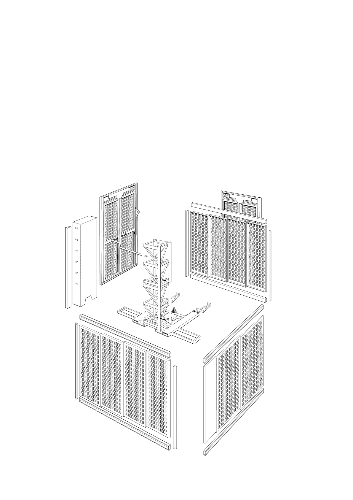
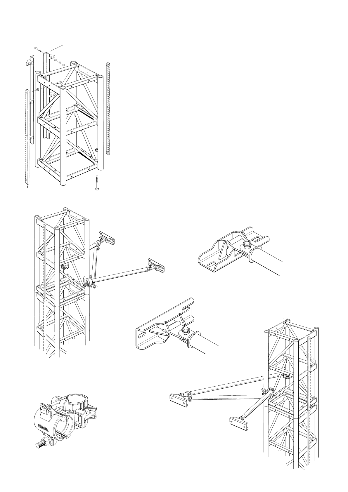
Alimak Scando 650 Series Parts list manual

Technical Description
ALIMAK SCANDO 650
Construction Hoists
YOUR HOIST HAS:
Manufacturing No.: Year: Part No. 9100272 - 1 03
2006 - 01 - 30
If the bottom right corner of this book is cut, the book is only valid for illustrative use!
This manual is only applicable if the manufacturing number indicated below corresponds to the manufacturing number stamped on the identification
sign of the equipment. Where there is a conflict contact your ALIMAK representative.

Photographs and drawings are illustrative only and do not necessarily show the design of the products on the market at any given point in time.
The products must be used in conformity with applicable practice and safety regulations. Specifications of the products and equipment
presented herein are subject to change without notice.

CONTENTS A
B
CC
DD
EE
FF
G
H
I
TECHNICAL DESCRIPTION
TECHNICAL DATA & SPECIFICATIONS
IMPORTANT SAFETY INSTRUCTIONS
OPERATING INSTRUCTIONS
SERVICE AND MAINTENANCE
ELECTRIC TROUBLESHOOTING
FOUNDATION
HOIST MAST
PREPARATIONS BEFORE INSTALLATION
See Operator’s Manual for chapter C, D, E and F.
Copyright © Alimak AB 2004.
All rights reserved.


TECHNICAL DESCRIPTION
General............................................................
Regulations......................................................
Foundation......................................................
Base frame.......................................................
Ground enclosure ...........................................
Hoist mast........................................................
Car ...................................................................
Drive unit.........................................................
Cable guiding device ......................................
Control systems...............................................
Landing equipment ........................................
Safety equipment............................................
Optional equipment........................................
The purchaser’s / user’s
own protective measures................................
Load signs........................................................
A 1
A 1
A 2
A 2
A 3
A 4
A 6
A 9
A 11
A 12
A 14
A 16
A 18
A 24
A 25
ALIMAK 34738 - 1/01
A0

2.8 m car base structure (9’- 2 1/4’’)
3.5 m car base structure (11’- 5 3/4’’)

Technical description
General
The new SCANDO 650 hoists are construction hoists for
personnel and materials transport. Two car base structures
can be combined with different gate units and extensions to a
number of different car lengths up to maximum 4.6 m (15’- 1’’).
Car width 1.5 m (4’- 11’’) is fixed.
The car, as well as the ground enclosures doors/gates, can be
positioned on any of the three sides away from mast.
The hoists have a lifting capacity of maximum 3200 kg
(7100 lbs.) up to a lifting height of 200 m (650 ft.).
Lifting speed is 38 m/min. (125 fpm.).
alt. 42, 54 or maximum 65 m/min. (135 , 175 or 215 fpm.)
with VFC-operation.
The SCANDO 650 construction hoist can be set up with
single or dual cars.
The hoist is easily transported by truck, to and from the
erection site and handled with forklift trucks or jib cranes on
the site.
The SCANDO 650 construction hoist is a part of the
SCANDO 650 access system and can be combined with
other products, i.e. platforms or materials hoists.
Regulations
The hoist and its mechanical and electrical components are
designed and dimensioned to conform to operating condi-
tions on contruction sites and fulfil demands according to EN
12159 and ANSI/ASME. The hoists and its components have
been thoroughly tested and conform to one or several of the
following international/national standards: IEC, CEE, EN,
DIN, UL, CSA, SS etc.
Necessary documents such as operator’s manual, wiring
diagrams, circuit diagrams and spare parts lists are delivered
with the hoist.
ALIMAK 34739 - 1/02
A1

Foundation
The foundation is a reinforced concrete slab and cast ”in place”
in accordance with instructions given under ”Preparations
before installation” and ”Concrete slab dimensions” in this
manual.
A transportable sheet steel foundation or a precast concrete slab
can also be used.
Base frame
The bottom mast section is bolted to the base frame, which
incorporates 3 buffer positions, channels for fork lifting and 2
boltable outriggers to support the enclosure.
The hoist can be used freestanding, bolted to the transportable
sheet steel foundation or the concrete slab.
With an additional buffer support the base frame also incorpo-
rates a dual car set up.
ALIMAK 34740 - 1/01
A2

Ground enclosure
The foundation is enclosed by 2500 mm (8’- 2 1/2’’) high
perforated steel sheet sections attached to the base frame.
The enclosure is built in modules and can easily be adapted for
different lengths as well as twin car set ups. It can also be
changed so that another SCANDO 650 modular system hoist/
platform can operate on the other side of the mast.
The enclosure is provided with one or two double-swing
mechanically locked and electrically monitored door(s).
Two entrance doors allow entrance to the car from 2 different
directions.
Doors can be positioned on any of the three sides away from
mast.
ALIMAK 34741 - 1/01
A3

Hoist mast
The square mast c/c 650 x 650 mm (2’- 1 1/8’’ x 2’- 1 1/8’’) is
the mainstay of the SCANDO 650 access system. The mast is
constructed of tubes and frames of high tensile steel and
fabricated in lenghts of 1508 mm (4’- 11 3/8’’). Each section is
provided with one or two bolted rack(s) module 5 and the
sections are bolted together with bolts and nuts.
The four guiding tubes and possibilities with two racks give
dual car set up advantages. Counterweight guide rail can be
bolted to all mast sections.
The ties are attached to the frames of the mast sections or alt. to
the rear mast tubes. The other end to special brackets attached
to the wall. The tie length is telescopic adjustable within
different intervals. The ties can also be inclined from the
horizontal. Specifications for each particular mast tie can be
found in chapter H.
Mast sections and mast ties are hot dipped galvanized with the
exception of the mast section rack.
Wall bracket bolt dimension is M24
A4Counterweight
guide rail
Corresponding wall
bracket can be installed
either on slab ...
a 210
... or against wall
ALIMAK 34742 - 1/02
Alimak original dia. 76 mm
pivoted tube coupler

The hoist stops automatically at the top and bottom by means of
cams attached to the hoist mast. The cams activate the normal
limit switches located on the hoist car. Additionally there is a
final limit switch activated by separate cams at the top and
bottom of the hoistway.
The final limit switch controls a main contactor, which switches
off all three phases of the main power supply to the drive
motor(s).
A5
Gränsbrytare
upp / ner
Slutgränsbrytare
upp / ner
ALIMAK 34743 - 1/03

Car
The car is sized to be suitable for ease of transport and is
constructed of high quality steel for strength and weight
reduction. The car walls are constructed of perforated steel
sheeting allowing light to enter and also give the operator a
clear view of the hoistway.
Individually adjustable ball bearing mounted guide roller
assemblies guide the car on the mast.
Car consists of multi layer built-up car floor with fire resistant
plastic material on galvanized steel sheet and aluminium
checker plate on top. The car roof is constructed of aluminium
checker plate.
The car has mechanically locked and electrically monitored
vertical guided entrance and exit doors.
The doors are modular for flexibility and in the SCANDO 650
access program, 4 different car doors are available. The
lightweight moving door blades consist of aluminium profiles
for ease of operation.
Normally the exit door is manufactured in two parts whereas the
entrance door is in one part. (The entrance door is the one
facing the door of the ground enclosure).
A 3.2 m (10’- 6’’) wide full height entrance door with C-side
location can be furnished for large cars with base structure
length greather than 3.2 m.
The exit door can also be combined with a folding load ramp in
2 different versions;
Manual folding load ramp . . .
ALIMAK 34744 - 1/01
A6
Car exit door in two parts
Full height entrance door
Car length extensions
Closed solid wall
Manual folding load ramp

. . . or fully automatic electro hydraulic folding load ramp.
The hydraulic system double acting cylinder opens and closes
the load ramp automatically at the landing and is operated by
the automatic floor call selection system, ALC II.
The electro hydraulic power pack is located on the floor portion
of the gate/ramp section.
As the car roof serves as working platform during erection, it is
provided with safety railing. There is also a trapdoor in the roof
and a ladder in the car to gain entry to the roof for erection
purposes.
Asymmetrical car configuration
The car length on each side of the mast shall be equal if
possible. The difference may only be one extension section of
0.35 m (1’- 1 3/4’’).
Although the hoist is asymmetrical it should be considered
symmetrical and the longer end dictating the maximum
allowable load.
A7
ALIMAK 34745 - 1/01
Hydraulic oil max./min. level
with closed/opened load ramp
can easily be seen on the cover
below the filler cap.
Filler cap
Fully automatic electro-hydraulic
folding load ramp

Erection crane, optional equipment
New type erection crane with manual adjustable jib equipped
with electric winch can be furnished.
Payload capacity 250 kg (550 lbs.) = jib radius 570 – 1060 mm.
(1’- 10 1/2’’ – 3’- 5 3/4’’)
Payload capacity 170 kg (370 lbs.) = jib radius 350 – 1700 mm.
(1’- 1 3/4’’ – 5’- 7’’)
Weight approx. 40 kg (88 lbs.), exclusive of electric winch.
Electric winch, 3 phase 440V, weight 13 kg (29 lbs.).
Movable erection platform, optional equipment
A manual movable erection platform to ease the mast section
assembly and the mast tie installation can be furnished with the
SCANDO 650 construction hoists.
Platform length adapted for different car lengths.
The platform reach is approximately 2 times its own length.
Payload capacity; 120 kg (265 lbs.).
Patent pending.
ALIMAK 34746 - 1/01
A8

Drive unit
A compact unit with two or three pinions engages the rack of
the mast. Each pinion is fitted to a high efficiency helical gear
box driven by a flexible coupling, by a direct start or frequency
controlled, squirrel cage induction motor with built-in electro-
magnetic disc brake.
The drive unit is connected to the car by pull rods.
The connection between car and drive unit means that the hoist
is prepared for an overload sensing system. (OSS).
The safety device is completely independent from the drive unit
and installed inside the car with two pinions engaging the rack.
The device is actuated by a centrifugal weight and stops the
hoist when the normal rated speed is exceeded.
FC vs DOL
Frequency controlled electric motors give:
– better (softer) riding comfort when starting and stopping.
– better stopping accuracy.
– less brake wear.
– hoist speed can be reduced during installation and inspection
procedures, which is not possible with direct on line (DOL)
started electric motors.
ALIMAK 34747 - 1/01
A9
Pulse encoder
on gearbox

A10

Cable guiding device
Type cable collecting basket
The trailing cable is coiled into a basket. U-shaped guides with
plastic springs along the hoistway guide the trailing power cable
between the cable collecting basket at ground level and the
cable attachment on the car.
Type cable trolley on separate guide rail
To be able to control the cables and to overcome the voltage
drop in the power cable at high lifting heights, the power cable
and control cable are fixed firmly to the mast from ground level
to a junction box in the mast halfway to the mast top.
The trailing power cable and the control cable from the junction
box to the cable brackets on the car are tensioned by cable
trollies. The cable trollies travel on a separate guide rail
attached close to the mast from ground level to a point halfway
to the mast top.
Differential expansion/contraction of the power and control
cable requires that the two trollies are not mechanically attached
to each other.
The method described above is also used for hoist installations
in harsh surroundings with highwinds, low temperature etc.
A11
ALIMAK 34749 - 1/01

ALIMAK 34750 - 1/01
A12
d 74
Control system
Three different systems are available:
a) Operator control system from the car only by means
of a joy-stick for travel up and down.
The system is automatic, i.e. the car stops as soon as
the joy-stick has been released (dead man type control)
b – c) ALIMAK Lift Control ALC
The ALC is a microprocessor based control with a main
software and two different control systems available:
Semi-Automatic control system and Collective control system
b) Semi-Automatic control system
This is a common control system but now developed to
work without any landing cams. The position of the
hoist is determined by counting impulses generated by
the pulse encoder attached to the gear box.
The machine can be operated from inside the hoist and if
chosen, also from the landings by using Up, Down and
Stop Next Landing push-buttons.
By pressing a button for up or down, the hoist starts
travelling in the chosen direction. When the hoist
approaches the desired landing, the button Stop Next
Landing is pressed. The hoist will then stop automati-
cally at the landing.
Calls/destinations from the landings transmit on three
230VAC control wires between the hoist and the
landings through the base panel. A destination order
from the hoist has three seconds priority over landing
calls.

c) Collective control system
This is an advanced control system available in the ALC
controller. The machine can be operated from inside the
hoist by destination push-buttons or a keypad and if
chosen, also called from the landings.
Each landing is provided with two Call buttons, one for
Up and Down resp.
The actual position and the hoist destination is shown on
displays inside the car.On these displays a fault indica-
tion is given.
ALIMAK 34751 - 1/01
A13
Push-button panels at landings
a 143
a 143

Landing equipment
In the SCANDO access system mechanically and electrically
interlocked double-leaf swing doors are included. Or mecha-
nically locked and electrically monitored horizontal sliding
gates at the landings.
The landing equipment can be installed by connecting
them to special brackets at the landings, in openings,
on projections or facade scaffoldings. It can also be
installed on vertical scaffold pipes parallel to the mast
from the ground enclosure to the mast top.
The electric interlocking of the landing equipment is
connected to the control system of the hoist (stop
circuit).
The landing el. equipment consists of a stainless
steel box with necessary control push-buttons for
calling the hoist. Connection cable as well as limit
switch or electromechanical locks for monitoring of
the landing door or alternatively the landing gate.
The equipment is provided with a 6-pole socket outlet
and plug on the connection cable in order to achieve a
quick, secure and proper connection to the control system
of the hoist. 10-pole socket outlet and plug alternately,
where ALC floor call selecting system occurs.
The electric equipment is delivered with connection cable in
lengths of 7 or 15 meter (23 or 49 ft.).
ALIMAK 34752 - 1/01
Additional side protection
A14
This manual suits for next models
2
Table of contents
Popular Chain Hoist manuals by other brands

Eller
Eller PH2 Series operating instructions

Performance Tool
Performance Tool W4005DB owner's manual

Grizzly
Grizzly G8709 instruction sheet

Tractel
Tractel Bravo AC 250 Installation, operating and maintenance manual

KITO
KITO NERP080S owner's manual

Northern Industrial
Northern Industrial HX-800 owner's manual

Yamato
Yamato H-250 instruction manual

Nitchi
Nitchi EC4 Series Operating and maintenance

Total
Total TLH1952 manual

Columbus McKinnon
Columbus McKinnon CM LODESTAR A-H Operating, Maintenance & Parts Manual

Forankra
Forankra WRH 800 Original instructions

STIER
STIER SPRO 0.75T-9T Operating & maintenance instruction manual