2P/N 192044557 REV AA September 2017
1-1. GENERAL INFORMATION
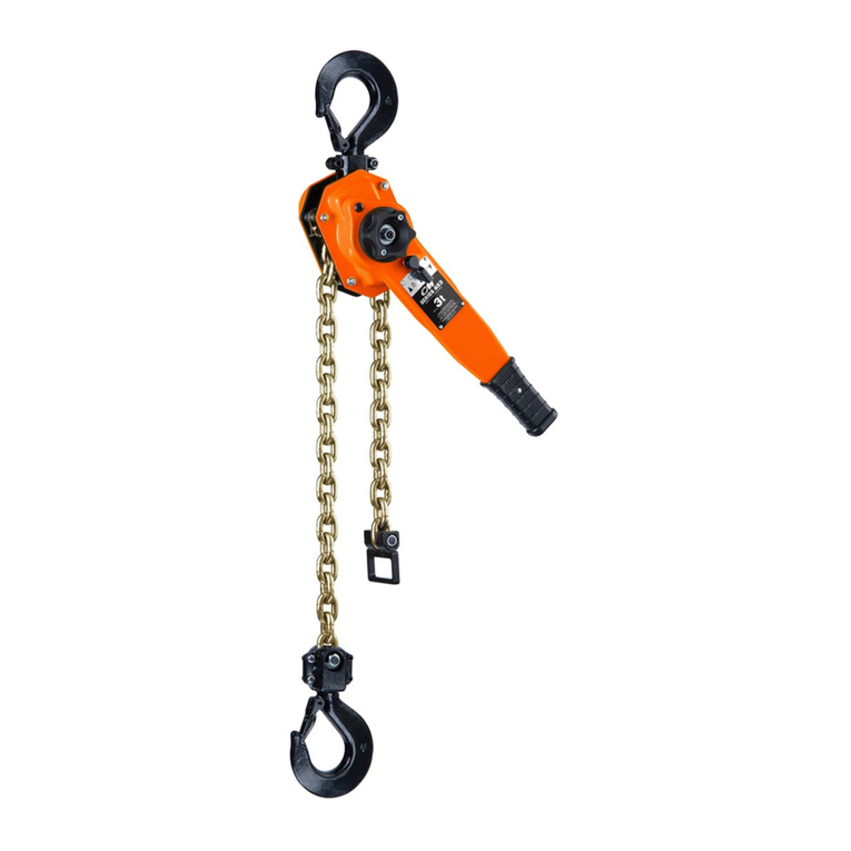
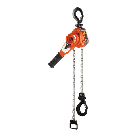
The CM Hurricane 360 O&M Manual (P/N 656) and this supplement
provide information for the safe operation and maintenance of
this hoist. All persons operating or maintaining these hoists
should be familiar with the information contained herein and
in the O&M manual. Adherence to the precautions, procedures,
and maintenance practices described should ensure long
reliable operation.
To safeguard against the possibility of personal injury or property
damage, follow the recommendations and instructions of this
manual. This manual contains important information for the correct
installation, operation, and maintenance of this equipment. All
persons involved in the installation, operation, and maintenance of
this equipment should be thoroughly familiar with the contents of this
manual. Keep this manual for reference and further use.
Using “Commercial” or other manufacturer’s parts to repair
the CM Hoists may cause load loss.
To avoid personal injury:
Use only CM supplied replacement parts. Parts may look alike but
CM parts are made of specic materials or processed to achieve
specic properties.
FIGURE 1: TOOLS REQUIRED
1. Hammer
2. Punch
3. Small at screwdriver
4. Torque wrench
5. Socket to t adjusting ring
6. Vise to secure load limiter
7. Special Sockets for adjusting load limiters
P/N 00401421 — Adjustment Tool 0.5T
P/N 00401422 — Adjustment Tool 1T
P/N 00401423 — Adjustment Tool 2T
P/N 00401424 — Adjustment Tool 3-10T
FIGURE 2: SPECIAL SOCKETS
NOTICE
To ensure proper function of the hoist load limiter systems,
perform the following steps:
STEP 1: Remove the hoist from the supporting structure and lay it
on a at working surface with the handwheel facing up.
Columbus McKinnon
Industrial Products GmbH
Yale-Allee 30
42329 Wuppertal / Germany
Modeled:
Drawn:
Approved:
Design Authority:
Original project:
Original scale:
1:3
Material:
General Tolerances
ISO 2768-mk
Dimensional Units
mm
Description:
Number:
Sheet
1
1
Format
F
E
D
C
B
A
1
2
3
4
A4
Columbus McKinnon
Industrial Products GmbH
Wuppertal / Germany
Columbus McKinnon Industrial Products GmbH claims proprietary rights in the material disclosed hereon. This drawing and/or technical information is issued in confidence
for engineering information only and may not be reproduced or used to manufacture anything shown or referred to hereon without direct permission
from Yale to the user. This drawing and/or technical information is loaned for mutual assistance and is subject to recall by Yale at any time.
This drawing and/or technical information is the property of Yale.
NOTICE TO PERSONS RECEIVING THIS DRAWING AND/OR TECHNICAL INFORMATION
ECN
Rev.
Description of change
Date
By
-
-
-
-
-
-
-
-
--
-
-
-
-
-
04/08/2008
04/08/2008
Velbert
kon3
kon3
Hurricane III 1,0/1
Hand chain hoist 1000/1
Flaschenzug 1000/1 - VG
84700017
kon6
04/14/2010
Standard:
Material No:
Specified Tolerances
ISO 8015
Edges According to
DIN 6784
First Angle Projection
STEP 2: Remove the three screws securing the plastic center cap
and remove the cap from the handwheel cover.
Columbus McKinnon
Industrial Products GmbH
Yale-Allee 30
42329 Wuppertal / Germany
Modeled:
Drawn:
Approved:
Design Authority:
Original project:
Original scale:
1:3
Material:
General Tolerances
ISO 2768-mk
Dimensional Units
mm
Description:
Number:
Sheet
1
1
Format
F
E
D
C
B
A
1
2
3
4
A4
Columbus McKinnon
Industrial Products GmbH
Wuppertal / Germany
Columbus McKinnon Industrial Products GmbH claims proprietary rights in the material disclosed hereon. This drawing and/or technical information is issued in confidence
for engineering information only and may not be reproduced or used to manufacture anything shown or referred to hereon without direct permission
from Yale to the user. This drawing and/or technical information is loaned for mutual assistance and is subject to recall by Yale at any time.
This drawing and/or technical information is the property of Yale.
NOTICE TO PERSONS RECEIVING THIS DRAWING AND/OR TECHNICAL INFORMATION
ECN
Rev.
Description of change
Date
By
-
-
-
-
-
-
-
-
--
-
-
-
-
-
04/08/2008
04/08/2008
Velbert
kon3
kon3
Hurricane III 1,0/1
Hand chain hoist 1000/1
Flaschenzug 1000/1 - VG
84700017
kon6
04/14/2010
Standard:
Material No:
Specified Tolerances
ISO 8015
Edges According to
DIN 6784
First Angle Projection
STEP 3: Block the load chain by inserting a screwdriver or pin
through the load chain just below the hoist frame. Operate the
handwheel in the up direction to remove the slack from the load
chain, closing and locking the brake.
Columbus McKinnon
Industrial Products GmbH
Yale-Allee 30
42329 Wuppertal / Germany
Modeled:
Drawn:
Approved:
Design Authority:
Original project:
Original scale:
1:3
Material:
General Tolerances
ISO 2768-mk
Dimensional Units
mm
Description:
Number:
Sheet
1
1
Format
F
E
D
C
B
A
1
2
3
4
A4
Columbus McKinnon
Industrial Products GmbH
Wuppertal / Germany
Columbus McKinnon Industrial Products GmbH claims proprietary rights in the material disclosed hereon. This drawing and/or technical information is issued in confidence
for engineering information only and may not be reproduced or used to manufacture anything shown or referred to hereon without direct permission
from Yale to the user. This drawing and/or technical information is loaned for mutual assistance and is subject to recall by Yale at any time.
This drawing and/or technical information is the property of Yale.
NOTICE TO PERSONS RECEIVING THIS DRAWING AND/OR TECHNICAL INFORMATION
ECN
Rev.
Description of change
Date
By
-
-
-
-
-
-
-
-
--
-
-
-
-
-
04/08/2008
04/08/2008
Velbert
kon3
kon3
Hurricane III 1,0/1
Hand chain hoist 1000/1
Flaschenzug 1000/1 - VG
84700017
kon6
04/14/2010
Standard:
Material No:
Specified Tolerances
ISO 8015
Edges According to
DIN 6784
First Angle Projection
When closing and locking the load brake with the load chain blocked
avoid applying more force than is needed to completely close the
brake. Applying too much force could result in the screwdriver or pin
blocking the load chain to bend or fracture.
