All-Star Scoreboards ALS-200LED User manual
1
INSTALLATION INSTRUCTIONS FOR
MODEL ALS-200LED SHOT CLOCKS
www.allstarscoreboards.com

2
Table of Contents
SHOT CLOCK INSTALLATION ........................................................................................................................... 3
THE SHOT CLOCK SYSTEM SHOULD INCLUDE THE FOLLOWING PARTS: ............................... 3
INSTRUCTIONS FOR REPORTING SHIPPING DAMAGE ......................................................................... 3
INSTALLATION OVERVIEW ............................................................................................................................... 4
PRODUCT SPECIFICATIONS .............................................................................................................................. 4
Overall D mens ons (each shot clock): ...................................................................................................... 4
We ght: .................................................................................................................................................................... 4
Power Requ rements (for each clock): ...................................................................................................... 4
Cable Requ rements: ......................................................................................................................................... 4
MOUNTING THE SHOT CLOCKS ON A WALL ............................................................................................. 5
SUSPENDING THE SHOT CLOCKS ................................................................................................................... 6
RUNNING & CONNECTING THE CONTROL CABLE .................................................................................. 7
For Stand Alone Installat ons: ....................................................................................................................... 7
At The Scorekeeper’s Locat on: .................................................................................................................... 7
RUNNING & CONNECTING THE CONTROL CABLE .................................................................................. 8
For Integrated Shot Clock Installat ons .................................................................................................... 8
At The Shot Clock: ........................................................................................................................................... 10
TESTING THE INSTALLED SYSTEM ............................................................................................................ 10
Connect ng cable-controlled systems: .................................................................................................... 10
Connect ng w reless systems: .................................................................................................................... 10
Test ng the scoreboard system: ................................................................................................................ 10
IMPORTANT! ......................................................................................................................................................... 12
Warranty Act vat on/Installat on & Complet on S gn Off Sheet ..................................................... 12

3
SHOT CLOCK INSTALLATION
NOTE TO INSTALLERS: PLEASE RETURN THIS MANUAL TO THE INDIVIDUAL IN CHARGE OF
THE SCOREBOARD UPON COMPLETION OF INSTALLATION.
The scoreboard and all accompanying accessories have been carefully inspected and tested before leaving the factory.
However, it is possible for damage to have occurred during shipping. Therefore, we ask that you inspect all shipping
containers upon arrival for damage and ensure that you have all of the parts listed below. Check the Shock Watch
sticker on the outside of each of the large packages. Please read and follow the instructions on the Shock Watch
stickers to ensure that there were no hard impacts to the scoreboard during shipping. If you find that damage has
occurred during shipping: 1) accept the shipment from the carrier…DO NOT refuse the shipment, 2) follow the instructions
for filing a freight damage claim found below, and 3) notify the manufacturer immediately.
THE SHOT CLOCK SYSTEM SHOULD INCLUDE THE FOLLOWING PARTS:
(2) 26” X 26” shot clocks, shipped in one (1) section each
(1) Hand held shot clock controller; connects directly to the LCD controller
(1) Customer-specified length of control cable (unless purchased from a separate vendor); to connect the shot clocks to
the scoreboards for integrated installations or directly to the scorekeeper’s location for stand-alone installations
(1) Documentation CD (including installation, operation, maintenance, warranty, and support information)
NOTE: Shot clocks purchased as part of an integrated system with scoreboard(s) are controlled by the scoreboard
controller using the hand held shot clock controller. This allows a second individual to conveniently control the shot clocks
while using only one LCD controller.
Shot clocks purchased for stand-alone installation (to be operated independently of scoreboard(s) should also
include the following parts):
(1) LCD controller with DC wall transformer and (3) keypad inserts
(2) Junction box covers with built-in receptacles; to be installed at scorekeeper’s location (one for each shot clock)
(2) 20-ft. control cables; to connect the LCD controller to the junction box covers (one for each shot clock)
(2) 6-ft control cables to connect at shot clock (one for each shot clock)
INSTRUCTIONS FOR REPORTING SHIPPING DAMAGE
Shipping damage must be noted at the time of delivery. Consignee must note “Damaged” on the
Delivery Receipt. Please make notations of the type of damage to the freight and to the packaging.
Ask the delivery driver to call the local terminal to report the freight damage immediately. The shipper
is not responsible for the shipments that are not signed for as damaged upon arrival. Please contact
the manufacturer immediately to report the damage. The shipper is responsible for filing the claim,
unless shipped 3RD Party.
If damage is discovered after delivery, call the delivery company to report the concealed damage and
please call the manufacturer immediately to report the damage. Concealed damage must be
reported within 5 days after delivery date. If the damages are found after this time, the manufacturer
will not be responsible for damage.

4
INSTALLATION OVERVIEW
This manual will walk you through the installation of the shot clocks step by step. Following is an
overview of the steps involved in the installation of the shot clocks. In order to make the installation
process as quick and easy as possible, follow these steps in order:
1. Review the product specifications below.
2. Mount the shot clocks on a wall, suspend them from a structure, or mount them on the
backboards.
3. Run and connect the control cable to each shot clock.
4. Run and connect the electrical service to each shot clock.
5. Test the installed system.
NOTE: For backboard or goal mounting instructions, please contact the manufacturer of your
goal/backboard.
NOTE: The control cable connected to the shot clocks will run from the scoreboard(s) for integrated
installations and directly from the scorekeeper’s location for stand-alone installations.
PRODUCT SPECIFICATIONS
Overall Dimensions (each shot clock):
26” L x 26” W x 8” D, shipped in one (1) section each.
Weight:
Hanging weight - approx. 35 lbs.
Shipping weight - approx. 60 lbs.
Power Requirements (for each clock):
(1) 120-volt, 20-amp, 60 Hz grounded AC circuit in a standard duplex outlet connected to a power
disconnect switch or circuit breaker
Cable Requirements:
Category 5 (twisted-pair) shielded data cable; Scoreboard part number CC-41A or equivalent
5
MOUNTING THE SHOT CLOCKS ON A WALL
1. Carefully remove each shot clock from its packaging, making sure not to pry against or cut into
the clock’s cabinet. Inspect each unit for shipping damage according to the instructions on
page 1.
2. Connect a lift device to the two hanging brackets on the top of the clock and lift the unit into
place. (See illustration below for location of hanging brackets.)
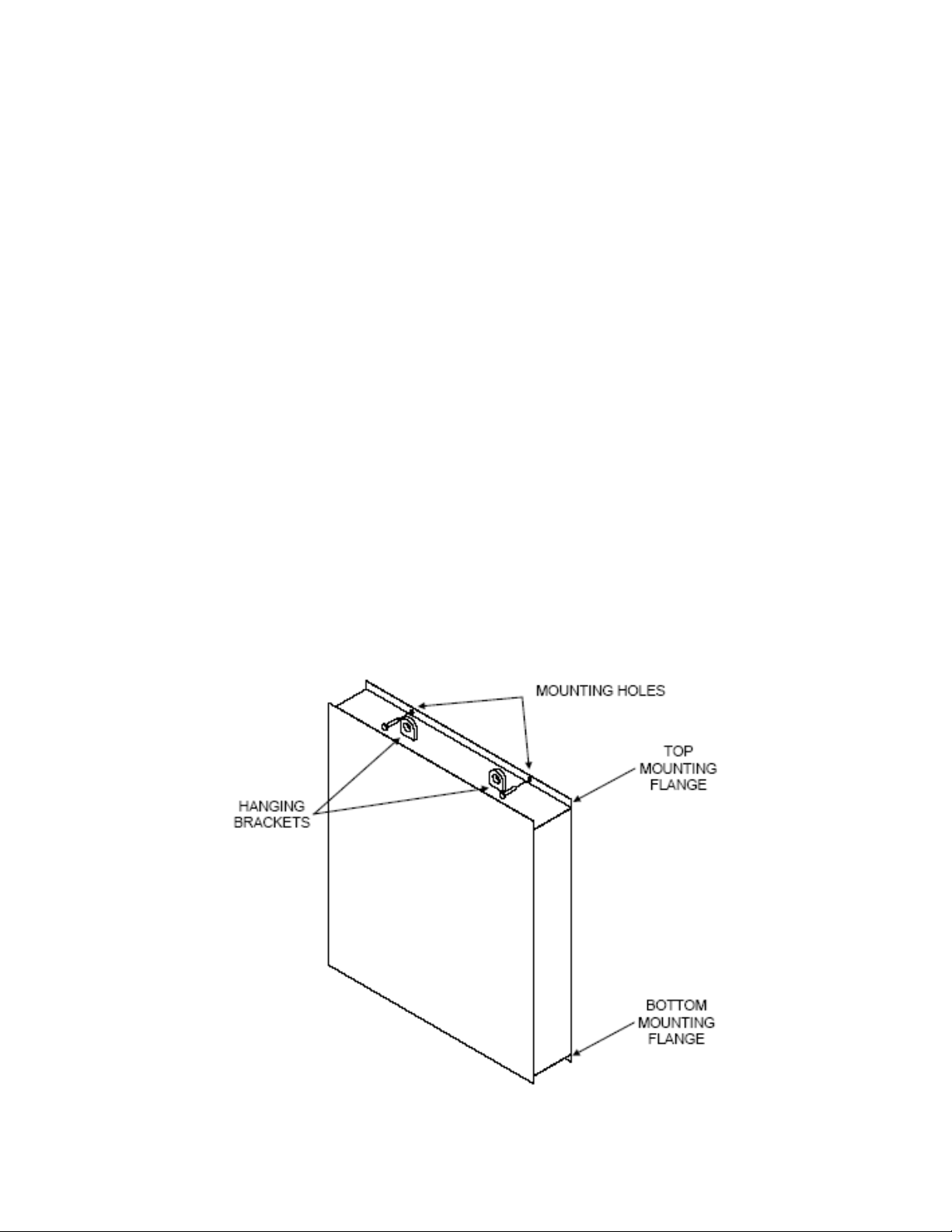
3. If anchors are to be used, use the pre-drilled mounting holes in the top and bottom mounting
flanges as a template for marking the drill locations for the anchors, two (2) through the top
mounting flange and two (2) through the bottom mounting flange.
4. Move the clock away from the wall and drill the holes for the anchors. Install the anchors in the
wall. (See illustration below for location of mounting flanges and mounting holes.)
5. Once the anchors are installed (or if no anchors are to be used) the clock may be fastened
securely to the wall. Use hardware appropriate for the surface to which the unit will be
mounted.
6. For concrete or concrete block walls, the use of bolts and anchors is recommended. No
mounting brackets are necessary as the pre-drilled mounting flanges on the top and bottom of
the clock are used to mount the unit directly to the wall.
7. The clock must be attached to the wall securely through both mounting holes in the top
mounting flange and both mounting holes in the bottom mounting flange. (See illustration
below for location of mounting holes and mounting flanges.)
6
SUSPENDING THE SHOT CLOCKS
1. Carefully remove each shot clock from its packaging, making sure not to pry against or cut into
the clock’s cabinet. Inspect each unit for shipping damage according to the instructions on
page 1.
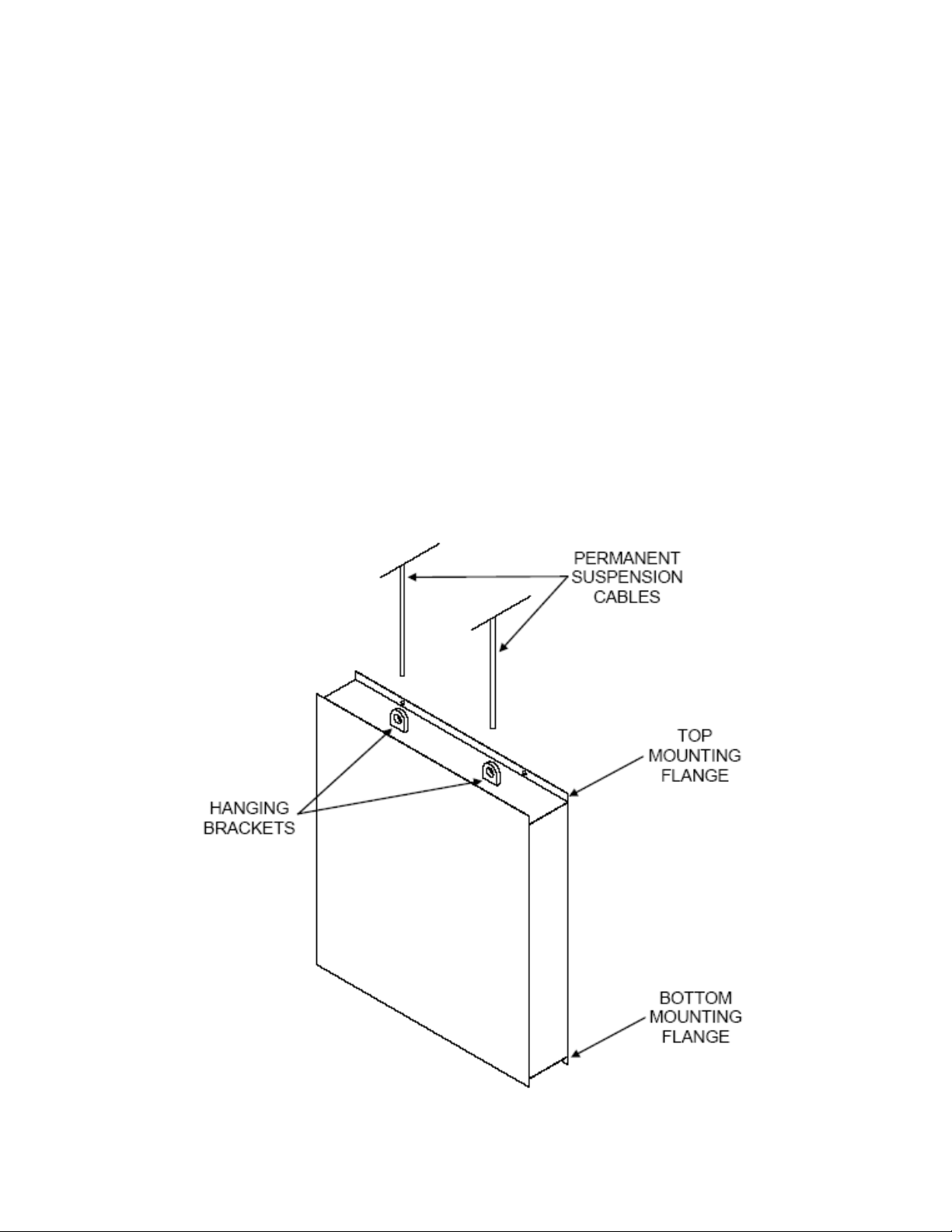
2. If the clock must be lifted into place before the permanent suspension cables can be attached
the unit may be raised into position by connecting a lift device to the two mounting holes in the
unit’s top mounting flange.
3. Then, two (2) separate suspension cables may be attached to the hanging brackets in the top
of the unit. (See illustration below for locations of mounting holes, top mounting flange, and
hanging brackets.)
4. If the clock is to be lifted into position using the same cables that will permanently suspend it,
these cables may be attached directly to the hanging brackets in the top of the unit. (See
illustration below for location of hanging brackets.)
NOTE: It is recommended that the cables that will be used to permanently suspend the
scoreboard be attached to the structure first, then to the clock’s hanging brackets after it is
lifted into position using a lifting device.
7
RUNNING & CONNECTING THE CONTROL CABLE
For Stand Alone Installations:
The control cable should run from each shot clock to a location that is within 10 feet of the
scorekeeper’s location terminating at two (2) 2”x4” wall boxes (one for each shot clock control cable).
1. The control cable must be run in conduit.
2. The control cable should NOT be run in the same conduit with electrical lines.
3. Install the wall plates with DIN sockets, one per wall box, by making up the wiring
connections as shown on the wall plate label.
4. The LCD controller will connect to the receptacles on the junction box covers via the
included 20-ft. control cables.
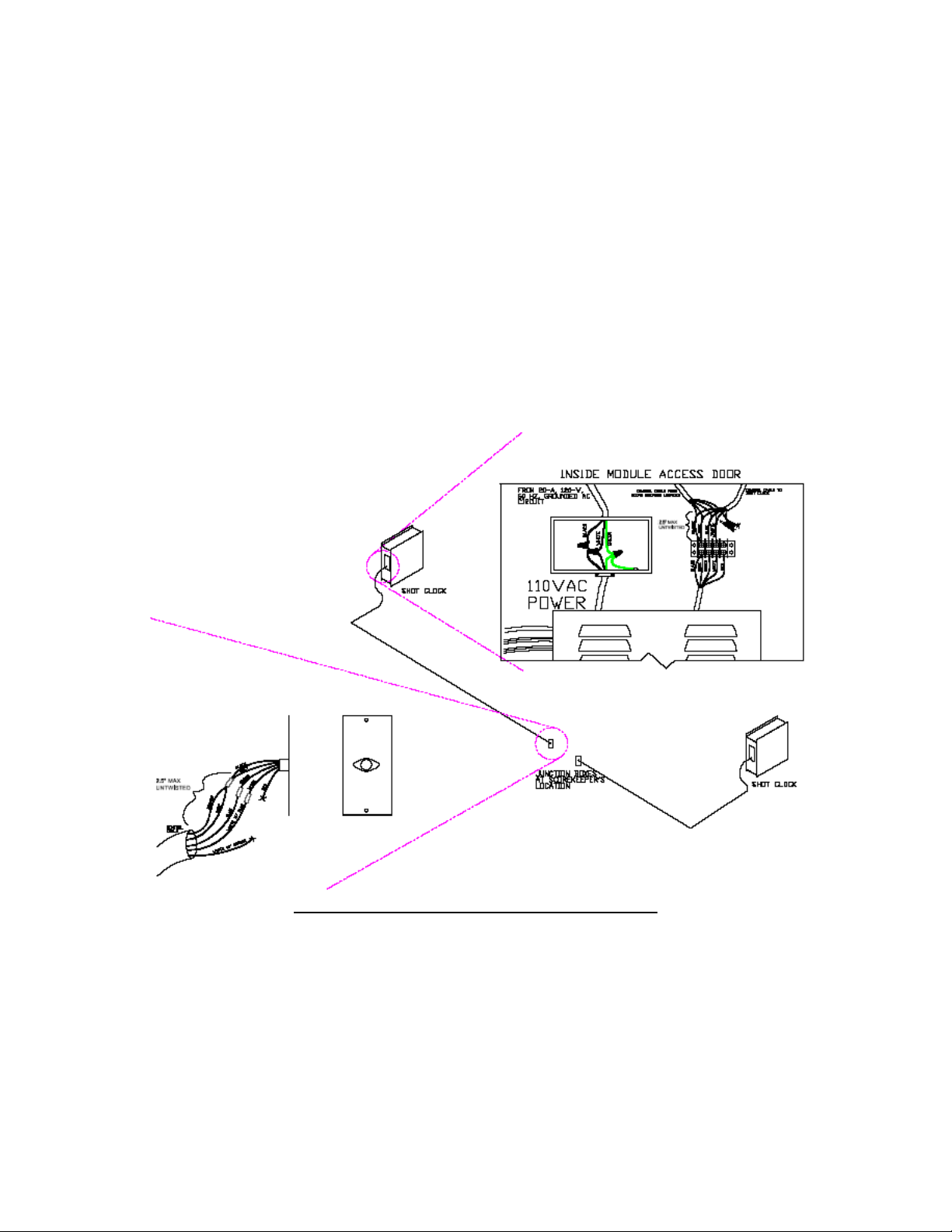
Shot Clock Installation – Stand Alone Application
At The Scorekeeper’s Location:
1. Connect the leads inside the control cables to those on the junction box covers.
2. Connect one control cable to one junction box cover and the second control cable to the
other junction box cover.
3. Connect the leads according to the label on the junction box covers. (See Image Below)

8
DO NOT CONNECT THE “WHITE W/ ORANGE” LEAD IN THE CONTROL CABLE TO THE “RED”
LEAD ON THE JUNCTION BOX COVER.
NOTE: If the colors of the wires in the control cables differ from those referenced on the labels or
shown in the following diagrams, make a note of how you match up the control cable at the junction
box cover. Match up the control cable to the terminal strip in the shot clock in the same manner.
•Secure the junction box covers to the installed junction boxes.
RUNNING & CONNECTING THE CONTROL CABLE
For Integrated Shot Clock Installations - One and Two Scoreboard Installation Method:
1. If there is only one scoreboard, the control cable will run from the scoreboard to the first
shot clock, then from the first shot clock to the second.
2. If there are two scoreboards, one shot clock will be connected to the nearest scoreboard
and the other will connect to the second scoreboard.
3. In either situation, the connections must match at all locations.
4. The control cable connecting the shot clocks to the scoreboard(s) must be run in conduit.
The control cable should NOT be run in the same conduit with electrical lines.
5. Whether the scoreboard(s) uses cable or wireless communication, the shot clocks are
always connected to the scoreboard(s) by control cable at a terminal block located inside
the scoreboard and shot clock.
6.
Scoreboards allow access to the electronic module and cable terminal block by opening the
HOME digit.

9
Shot Clock Installation – Integrated Application
At The Scoreboard:
1. Open the module access door (HOME score digit) by removing the screws securing it.
2. Bring the control cable (from the shot clock) into the scoreboard through one of the two conduit
holes in the top of the scoreboard, located directly above the HOME score digit, and run it
down to the cable terminal block located just above the scoreboard’s electronic module.
DO NOT CONNECT THE “WHITE W/ ORANGE” LEAD IN THE CONTROL CABLE TO THE “RED”
LEAD ON THE CABLE TERMINAL BLOCK.

10
NOTE: If the colors of the wires in the control cable differ from those referenced on the label or
shown in the following diagrams, make a note of what wire colors you match up at the scoreboard
and do the same at the shot clock
1. Connect the control cable leads to the appropriate terminals on the terminal block,
according to the label above the terminal block.
2. Close and secure the module access door.
At The Shot Clock:
1. Open the front panel of the shot clock by removing the screws that hold it closed.
2. Bring the control cable (from the shot clock) into the shot clock through the conduit hole
in the top of the shot clock and run it down to the terminal block located just above the
shot clock’s electronic module.
3. Connect the control cable leads to the appropriate terminals on the terminal block,
according to the connections at the scoreboard.
4. Close and secure the front panel of the shot clock.
TESTING THE INSTALLED SYSTEM
NOTE: Please refer to the INSTRUCTION MANUAL included with the scoreboard and/or shot
clocks for detailed instructions on how to connect the controller to the scoreboard and shot
clocks and for detailed controller operation instructions.
Connecting cable-controlled systems:
Connect one end of the supplied 20-ft. control cable into either of the two control cable jacks on the
back of the controller and the other into the receptacle on the supplied junction box cover installed at
the scorekeeper’s location.
Connecting wireless systems:
Connect the wireless transmitter to the controller using the interface cable already attached to the
transmitter by plugging the free end of the interface cable into either of the control cable jacks on the
back of the controller.
Testing the scoreboard system:
1. Connect the appropriate end of the 12-volt DC wall transformer to the power receptacle
on the back of the controller.
2. Plug the transformer into a live, 120-volt outlet.
3. Turn on the power to the shot clocks and/or scoreboard(s)
4. Place the system in DIAGNOSTIC MODE and turn on every digit and indicator:
5. With the controller and the shot clocks and/or scoreboard(s) ON, press and hold the
OPTION key while turning the controller ON. The controller’s LCD will read: SELECT
DIAG MODE <SEGMENT TEST>
6. Press ENTER. The controller’s LCD will read: SEGMENT TEST <ALL SEGMENTS
OFF>

11
7. Press the up arrow once. The controller’s LCD will read: SEGMENT TEST <ALL
SEGMENTS ON>
All working displays will now be on. To return to game mode press RESET followed by ENTER.
If at any time during the installation process you have a question to which the answer cannot be
found in this manual, please call Scoreboard Service Company at (800) 411-3136. Technicians are
on call 24 hours a day to answer all of your installation, operation, and maintenance questions.

12
IMPORTANT!
Warranty Activation/Installation & Completion Sign Off Sheet
NOTE: This sheet must be completely filled out and returned/faxed (270) 753-3773 to Scoreboard
Service Company before your warranty can be activated.
Your Serial Number _______________________________________
Your Model Number _______________________________________
Date Purchased _______________________________________
Sales Agent _______________________________________
Person Authorizing Purchase (title) ____________________________
Date Installation Completed _________________________________
Company or Person Responsible
For Installation (address/phone number) ________________________
This document confirms that the installation for the 26” x 26” Basketball Shot Clocks has been
completed. All structural, wiring, and power requirements have been met. This unit has been
tested in scoring and diagnostic modes, ensuring the functionally of the unit.
________________________________
Scoring/timing equipment responsible party
________________________________
Installer
So that we may better serve you, please have this information available in the event you need to
call technical support. Technical Support: 1-800-411-3136

13
Table of contents
Popular Clock manuals by other brands

Bramwell Brown
Bramwell Brown Tide Clock instruction manual

La Crosse Technology
La Crosse Technology C86279 Instructional manual

La Crosse Technology
La Crosse Technology C86279 Faqs

GlobalTime Electronic Co., Ltd
GlobalTime Electronic Co., Ltd GTD360 Installation and user manual

Davtron
Davtron 811C installation manual

Cypress
Cypress CY3672-USB manual


SOUNDMASTER
SOUNDMASTER FUR4005 instruction manual

Honeywell
Honeywell TRS-3300 Installation and operating instructions

hopf
hopf 6021GPS Technical manual

Oregon Scientific
Oregon Scientific BAR223P user manual

Proxdata
Proxdata TR515 FAQ and Troubleshooting

La Crosse Technology
La Crosse Technology WT-3102 user manual