hopf 6021GPS User manual

_____________________________________________________________
Technical Manual
GPS Satellite Clock
Model 6021GPS
ENGLISH
Version: 01.00
-
24.08.2006
_____________________________________________________________
Valid for Devices 6021GPS with FIRMWARE Version: 01.xx
and REMOTE-SOFTWARE Version: 01.xx
Industriefunkuhren

2 / 41 6021GPS GPS Satellite Clock - V01.00
hopf Elektronik GmbH
Nottebohmstr. 41
•
D-58511 Lüdenscheid
•
Tel.: +49 (0)2351 9386-86
•
Fax: +49 (0)2351 9386-93
•
Internet: http://www.hopf.com
•

INPORTANT NOTES
6021GPS GPS Satellite Clock - V01.00 3 / 41
hopf Elektronik GmbH
Nottebohmstr. 41
•
D-58511 Lüdenscheid
•
Tel.: +49 (0)2351 9386-86
•
Fax: +49 (0)2351 9386-93
•
Internet: http://www.hopf.com
•
Version number (Firmware / Manual)
THE FIRST TWO DIGITS OF THE VERSION NUMBER OF THE TECHNICAL MANUAL AND
THE FIRST TWO DIGITS OF THE FIRMWARE VERSION MUST COMPLY WITH
EACH OTHER. THEY INDICATE THE FUNCTIONAL CORRELATION BETWEEN DEVICE AND
TECHNICAL MANUAL.
THE DIGITS AFTER THE POINT IN THE VERSION NUMBER INDICATE CORRECTIONS IN
THE FIRMWARE / MANUAL THAT ARE OF NO SIGNIFICANCE FOR THE FUNCTION.
Downloading Technical Manuals
All current manuals of our products are available free of charge via our homepage on the
Internet.
Homepage: http://www.hopf.com
E-mail: [email protected]
Symbols and Characters
Operational Reliability
Disregard may cause damages to persons or material.
Functionality
Disregard may impact function of system/device.
Information
Notes and Information.

SERVICE RELIABILITY
4 / 41 6021GPS GPS Satellite Clock - V01.00
hopf Elektronik GmbH
Nottebohmstr. 41
•
D-58511 Lüdenscheid
•
Tel.: +49 (0)2351 9386-86
•
Fax: +49 (0)2351 9386-93
•
Internet: http://www.hopf.com
•
Safety regulations
The safety regulations and observance of the technical data serve to
ensure trouble-free operation of the device and protection of persons and
material. It is therefore of utmost importance to observe and compliance
with these regulations.
If these are not complied with, then no claims may be made under the
terms of the warranty. No liability will be assumed for any ensuing
damage.
Safety of the device
This device has been manufactured in accordance with the latest
technological standards and approved safety regulations
The device should only be put into operation by trained and qualified staff.
Care must be taken that all cable connections are laid and fixed in
position correctly. The device should only be operated with the voltage
supply indicated on the identification label.
The device should only be operated by qualified staff or employees who
have received specific instruction.
If a device must be opened for repair, this should only be carried out by
employees with appropriate qualifications or by hopf Elektronik GmbH.
Before a device is opened or a fuse is changed all power supplies must
be disconnected.
If there are reasons to believe that the operational safety can no longer be
guaranteed the device must be taken out of service and labelled
accordingly.
The safety may be impaired when the device does not operate properly or
if it is obviously damaged.
CE-Conformity
This device fulfils the requirements of the EU directive
89/336/EWG "Electromagnetic compatibility" and 73/23/EWG "Low
voltage equipment".
Therefore the device bears the CE identification marking
(CE = Communautés Européennes = European communities)
The CE indicates to the controlling bodies that the product complies with the requirements of
the EU directive - especially with regard to protection of health and safety for the operator
and the user - and may be released for sale within the common markets.

TABLE OF CONTENTS
6021GPS GPS Satellite Clock - V01.00 5 / 41
hopf Elektronik GmbH
Nottebohmstr. 41
•
D-58511 Lüdenscheid
•
Tel.: +49 (0)2351 9386-86
•
Fax: +49 (0)2351 9386-93
•
Internet: http://www.hopf.com
•
Contents Page
1General ............................................................................................................................ 7
2Hardware ......................................................................................................................... 8
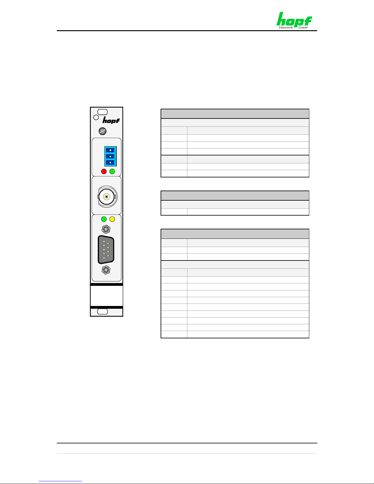
2.1 Front Panel.................................................................................................................. 8
2.1.1 GPS Antenna Connection.................................................................................................... 9
2.1.2 Status LEDs ......................................................................................................................... 9
2.1.3 Status Optical Coupler ......................................................................................................... 9
2.1.4 Remote Interface.................................................................................................................. 9
2.2 Assignment of the VG ledge 64-pole ........................................................................ 10
2.2.1 Voltage Feed...................................................................................................................... 11
2.2.2 Serial Time String Output................................................................................................... 11
2.3 Back-up Clock ........................................................................................................... 11
3Remote Software .......................................................................................................... 12
3.1 General ..................................................................................................................... 12
3.2 Installation / Uninstallation ........................................................................................ 12
3.2.1 Operating Systems............................................................................................................. 12
3.2.2 Installation .......................................................................................................................... 12
3.2.3 Uninstalling the Board........................................................................................................ 12
3.3 Create Remote Connection....................................................................................... 13
3.3.1 PC Port............................................................................................................................... 13
3.3.2 Connect / Disconnect ......................................................................................................... 13
3.3.3 Remote Connection Status ................................................................................................ 13
3.4 Operation / Display.................................................................................................... 14
3.4.1 General Colour Scheme .................................................................................................... 14
3.4.2 Function Button .................................................................................................................. 14
3.4.2.1 RESET Button ............................................................................................................................ 14
3.4.2.2 SET DEFAULT Button ................................................................................................................ 15
3.4.2.3 SET Button ................................................................................................................................. 16
3.4.2.4 REFRESH Button ....................................................................................................................... 16
3.5 Info Window .............................................................................................................. 16
3.6 Time Window ............................................................................................................ 17
3.6.1 Time ................................................................................................................................... 17
3.6.2 Time Offset......................................................................................................................... 18
3.6.3 Daylight Saving Time (Summer Time)............................................................................... 19
3.6.4 SyncON / SyncOFF............................................................................................................ 20
3.6.5 Error Status ........................................................................................................................ 21
3.7 GPS Window............................................................................................................. 22
3.7.1 Position .............................................................................................................................. 22
3.7.2 Satellites............................................................................................................................. 23
3.7.3 3D / Position-fix (GPS Mode)............................................................................................. 24
3.8 Status OC Window.................................................................................................... 25
3.9 Serial Port Window.................................................................................................... 26
3.9.1 Serial Interface Parameters ............................................................................................... 27

TABLE OF CONTENTS
6 / 41 6021GPS GPS Satellite Clock - V01.00
hopf Elektronik GmbH
Nottebohmstr. 41
•
D-58511 Lüdenscheid
•
Tel.: +49 (0)2351 9386-86
•
Fax: +49 (0)2351 9386-93
•
Internet: http://www.hopf.com
•
3.9.1.1 Data String.................................................................................................................................. 27
3.9.1.2 Baud Rate................................................................................................................................... 27
3.9.1.3 Parity........................................................................................................................................... 27
3.9.1.4 Data Bits ..................................................................................................................................... 27
3.9.1.5 Stop bits...................................................................................................................................... 27
3.9.1.6 Time Base................................................................................................................................... 27
3.9.1.7 Control Characters...................................................................................................................... 27
3.9.1.8 Send Scheme ............................................................................................................................. 27
3.9.1.9 Delayed Transmission ................................................................................................................ 29
3.9.1.10 Send Cycle ................................................................................................................................. 29
3.9.1.11 Change of <CR> <==> <LF> - .................................................................................................... 29
3.9.2 Serial Transmission Data Format ...................................................................................... 30
3.9.3 hopf Standard String (6021)............................................................................................. 30
3.9.3.1 Specified Settings ....................................................................................................................... 30
3.9.3.2 Structure ..................................................................................................................................... 30
3.9.3.3 Status.......................................................................................................................................... 31
3.9.3.4 Example...................................................................................................................................... 32
3.9.3.5 Serial Requests with ASCII Characters (hopf Standard and hopf 2000) ................................. 32
3.10 PCID Window............................................................................................................ 33
4Fault Analysis / Troubleshooting ................................................................................ 34
4.1 Fault Scenarios ......................................................................................................... 34
4.1.1 Complete Failure................................................................................................................34
4.1.2 No GPS Reception / No Synchronization .......................................................................... 34
4.1.3 No Serial Output or Serial Output Incorrect ....................................................................... 36
4.1.4 Incorrect Time Output ........................................................................................................ 36
4.1.5 No ST/WT Changeover...................................................................................................... 36
4.2 Support from the hopf Company ............................................................................. 37
5Maintenance / Care ....................................................................................................... 38
6Technical Data .............................................................................................................. 39
7Appendix ....................................................................................................................... 41
7.1 GPS (Global Positioning System) ............................................................................. 41

GENERAL
6021GPS GPS Satellite Clock - V01.00 7 / 41
hopf Elektronik GmbH
Nottebohmstr. 41
•
D-58511 Lüdenscheid
•
Tel.: +49 (0)2351 9386-86
•
Fax: +49 (0)2351 9386-93
•
Internet: http://www.hopf.com
•
1 General
The hopf_Board 6021GPS is a further development of the DCF77 Radio-controlled Clock
Board 6021. The highly accurate synchronization of the Board takes place via the GPS
satellite system, which is available worldwide.
The dimensions of the switching boards correspond to the standard format for Euro-boards
with 3U/4HP front panel (U = Height Unit / HP = Horizontal Pitch) for installation in
19" racks:
Some of the system’s basic functions:
• Synchronization can be realized with only one satellite
• Simple operation using remote software
• Remote interface on the front panel (RS232 format)
• Status LEDs on the front panel
• Status output via two relays (dry contact) for power and synchronization
• Serial interfaces (RS232 and RS422 formats)
• High freewheel accuracy through GPS-supported regulation of the internal quartz
base
• Potential isolation of the GPS antenna circuit
• Completely maintenance-free system
• SyncOFF timer (reception failure bypassing) for operation free of fault messages -
even in difficult reception conditions
• Redundant multiple validation of the synchronization signal for fault-free and leap-
free signal evaluation
• Maintenance-free, buffered back-up clock for three days
Software supplied:
• Remote software for PC
for Windows 98SE, NT, 2000 and XP operating systems
Accessories supplied:
• Serial programming cable (2m, 9-pole socket to 9-pole socket)

HARDWARE
8 / 41 6021GPS GPS Satellite Clock - V01.00
hopf Elektronik GmbH
Nottebohmstr. 41
•
D-58511 Lüdenscheid
•
Tel.: +49 (0)2351 9386-86
•
Fax: +49 (0)2351 9386-93
•
Internet: http://www.hopf.com
•
2 Hardware
This chapter describes the different hardware details of the board.
2.1 Front Panel
6021
GPS
Status
1
2
3
RD GN
GPS
Antenna
Remote
Rx Tx
Status (LEDs + Optical Coupler)
3-pole Connector
Pin Signal
1 Collector
2 n.c.
3 Emitter
LED Meaning
RD Status LED red
GN Status LED green
GPS Antenna
BNC connector
GPS Antenna Input
Remote
LED Meaning
Rx LED green - reception of serial data
Tx Led yellow - transmission of serial data
9-pole SUB-D connector
Pin Signal
1 n.c.
2 RS232c (V.24) RXD
3 RS232c (V.24) TXD
4 n.c.
5 GND
6 n.c.
7 n.c.
8 n.c.
9 n.c.
n.c. = not connected

HARDWARE
6021GPS GPS Satellite Clock - V01.00 9 / 41
hopf Elektronik GmbH
Nottebohmstr. 41
•
D-58511 Lüdenscheid
•
Tel.: +49 (0)2351 9386-86
•
Fax: +49 (0)2351 9386-93
•
Internet: http://www.hopf.com
•
2.1.1 GPS Antenna Connection
The coaxial cable of the GPS antenna equipment is connected to the BNC socket marked
"GPS Antenna" on the front panel. Further specifications concerning the installation of the
antenna equipment, such as cable lengths and cable types, can be found in the document
titled "GPS Antenna Equipment".
2.1.2 Status LEDs
The status LEDs on the front panel signal the Board’s current (synchronization) status. The
meanings of the LEDs are as follows:
LED
Red
LED
Green Status STATUS Code
Off ON Sync (radio-synchronous) with quartz regulation SYNC
Off Flashing Sync (radio-synchronous) - SyncOFF timer
running
SYOF
Flashing ON Sync (radio-synchronous) – simulation mode SYSI
Flashing Flashing Quartz - SyncON timer running QUON
ON ON
Quartz – time was set via synchronization
source
QUEX
ON Flashing Quartz – time set manually or after reset QUSE
ON Off No valid time INVA
Off Off
No operating voltage / faulty ---
2.1.3 Status Optical Coupler
The status optical coupler provides a potential isolated switching contact for monitoring the
Board’s synchronization status.
Status output via 3-pole terminal with selection of the desired system status at which
reporting is to be activated:
Optical coupler:
• Selected status or better achieved – Optical coupler switched through
• Selected status not achieved – Optical coupler blocked
The desired reporting status is set via the remote software.
2.1.4 Remote Interface
The connection to a PC’s RS232 serial interface is made by means of the KA6870 interface
cable supplied.
The remote interface for the configuration of the Board is located on the front panel of the
Board. The transmission line (Tx) and reception line (Rx) have status LEDs which signal the
activity on the respective interface line.
No further configuration of this remote interface is necessary.

HARDWARE
10 / 41 6021GPS GPS Satellite Clock - V01.00
hopf Elektronik GmbH
Nottebohmstr. 41
•
D-58511 Lüdenscheid
•
Tel.: +49 (0)2351 9386-86
•
Fax: +49 (0)2351 9386-93
•
Internet: http://www.hopf.com
•
2.2 Assignment of the VG ledge 64-pole
ca
32
1
20
10
C
o
nn
e
c
t
o
r,
D
IN4
1
6
1
2, 64-pin
V
G
m
a
l
e
Connector, DIN 41612,
64-pin VG male
Pin c a Pin
1 n.c. n.c.
1
2 n.c. RS232c (V.24) TXD 2
3 n.c. RS232c (V.24) RXD 3
4 n.c. n.c.
4
5 n.c. n.c.
5
6 n.c. n.c.
6
7 n.c. GND 7
8 n.c. n.c.
8
9 n.c. GND 9
10 n.c. RS422 (V.11) -TXDL10
11 n.c. RS422 (V.11) +TXDH11
12 n.c. RS422 (V.11) -RXDL12
13 n.c. RS422 (V.11) +RXDH13
14 n.c. GND 14
15 n.c. n.c.
15
16 n.c. n.c.
16
17 n.c. n.c.
17
18 n.c. n.c.
18
19 n.c. n.c.
19
20 n.c. n.c.
20
21 n.c. n.c.
21
22 n.c. n.c.
22
23 n.c. n.c.
23
24 n.c. n.c.
24
25 n.c. n.c.
25
26 n.c. n.c.
26
27 n.c. n.c.
27
28 n.c. n.c.
28
29 n.c. n.c.
29
30 n.c. n.c.
30
31 GND GND
31
32 +5V DC +5V DC 32
n.c. = not connected
Row b= not connected
LRS422 (V.11) low aktiv
HRS422 (V.11) high aktiv

HARDWARE
6021GPS GPS Satellite Clock - V01.00 11 / 41
hopf Elektronik GmbH
Nottebohmstr. 41
•
D-58511 Lüdenscheid
•
Tel.: +49 (0)2351 9386-86
•
Fax: +49 (0)2351 9386-93
•
Internet: http://www.hopf.com
•
2.2.1 Voltage Feed
The voltage feed takes place via the Board’s VG-ledge.
2.2.2 Serial Time String Output
The Board 6021GPS has serial interfaces without handshake lines for transmitting time
information. Data exchange can take place via RS232c (V.24) or RS422 (V.11) signal level.
The interfaces may be used, for example, to transmit time telegrams to other computers.
The serial time string is transmitted via the Board’s VG-ledge.
2.3 Back-up Clock
The Board has a maintenance-free back-up clock. This back-up clock buffers the time
information for up to 3 days following a power failure.
After a power failure lasting less than 3 days, the clock starts with the internal back-up clock
information unless valid time information was available beforehand.

REMOTE SOFTWARE
12 / 41 6021GPS GPS Satellite Clock - V01.00
hopf Elektronik GmbH
Nottebohmstr. 41
•
D-58511 Lüdenscheid
•
Tel.: +49 (0)2351 9386-86
•
Fax: +49 (0)2351 9386-93
•
Internet: http://www.hopf.com
•
3 Remote Software
This Chapter describes the operation and functionality of the remote software for the Board
6021GPS.
3.1 General
The remote software is divided into various sectors and functionalities:
• Setting and status of remote communication
• Time – time and status information and parameters for the calculation of time
• GPS – GPS display and parameters
• Status OC – parameterization of the status OC
• Serial Port – parameterization of the serial time string output
• PCID – base and configuration data of the Board 6021GPS
• Info – programme version / contact data for the hopf company /
Uninstall Program button
• RESET and DEFAULT setting
3.2 Installation / Uninstallation
The remote software is in a single file with the following name:
Remote6021GPS.EXE.
3.2.1 Operating Systems
The remote software for the Board 6021GPS is suitable for the following operating systems:
• Windows 98SE
• Windows NT
• Windows 2000
• Windows XP
3.2.2 Installation
It is not necessary to install the Remote6021GPS.EXE programme. The programme is
simply copied to the folder on the hard disk from which it is to be started.
3.2.3 Uninstalling the Board
Entries take place in the registry while the programme is running. These entries are removed
when the programme is uninstalled using the Uninstall Program button in the Info-
window.
The user must then delete the Remote6021GPS.EXE programme manually.

REMOTE SOFTWARE
6021GPS GPS Satellite Clock - V01.00 13 / 41
hopf Elektronik GmbH
Nottebohmstr. 41
•
D-58511 Lüdenscheid
•
Tel.: +49 (0)2351 9386-86
•
Fax: +49 (0)2351 9386-93
•
Internet: http://www.hopf.com
•
3.3 Create Remote Connection
After a connection has been made between the remote interface of the Board 6021GPS and
a free serial interface on the PC, the PC COM port used must be set up in the remote
software.
After activating the Connect button, the remote software attempts to build a connection
to the Board 6021GPS. The status element changes colour dependent on the respective
connection status.
3.3.1 PC Port
The desired/used serial port of the PC is selected here.
Value range
PC Port PC Port: COM1 ... COM49 directly selectable.
Input COM1 ... COM9999 possible!
3.3.2 Connect / Disconnect
The Connect button is activated in order to make the remote serial connection with the
Board 6021GPS.
After the interface has been successfully initialized, the Disconnect button is displayed,
by means of which the PC’s interface can be re-enabled for other programmes without
exiting the programme.
3.3.3 Remote Connection Status
The status display for the remote connection is located next to the Connect /
Disconnect button. The element changes colour dependent on the current status of the
connection.
GREEN Connection established with Board 6021GPS (device has responded).
YELLOW PC interface initialized but no response received from Board 6021GPS.
GREY The interface on the PC is not available or is being used by another
programme. A message is also displayed.
The colour field also turns YELLOW if the serial connection is interrupted during operation.

REMOTE SOFTWARE
14 / 41 6021GPS GPS Satellite Clock - V01.00
hopf Elektronik GmbH
Nottebohmstr. 41
•
D-58511 Lüdenscheid
•
Tel.: +49 (0)2351 9386-86
•
Fax: +49 (0)2351 9386-93
•
Internet: http://www.hopf.com
•
3.4 Operation / Display
3.4.1 General Colour Scheme
Each combination of script and background colour defines the meaning of the respective
display.
Black text on light grey background ÖLabelling of fields etc.
Black text on white background ÖData from the PC
Grey text on white background ÖNon-modifiable data received from device
Green text on white background ÖData received from device / confirmed
Yellow text on grey background ÖTransmitted data (waiting for response)
Red text on white background ÖModified data not (yet) transmitted
Black text on red background ÖError message (if error present)
Black text on green background ÖActive timer
3.4.2 Function Button
Various function buttons are available in the programme.
3.4.2.1 RESET Button
This button is used to trigger a hardware reset of the Board. This leads to a defined restart of
the Board’s microcontroller.
This function has no effect on the fail-safe stored data

REMOTE SOFTWARE
6021GPS GPS Satellite Clock - V01.00 15 / 41
hopf Elektronik GmbH
Nottebohmstr. 41
•
D-58511 Lüdenscheid
•
Tel.: +49 (0)2351 9386-86
•
Fax: +49 (0)2351 9386-93
•
Internet: http://www.hopf.com
•
3.4.2.2 SET DEFAULT Button
After activating the Set Default button and an additional security inquiry the settings of
Board 6021GPS are set to the following values:
1. Deletion of the current leap second information
2. Time settings
• Time offset = +00.00
• Changeover points of time:
Commencement of summer time = deactivated
End of summer time = deactivated
• SyncON / SyncOFF timeout = 0000 / 0002 (minutes)
3. GPS settings
• GPS position:
Longitude = E 000° 00' 0000
Latitude = N 00° 00' 0000
• GPS reception mode = Position-fix
4. Status optical coupler
ZZZZ (synchronization status) = SYNC
5. Time string output
hopf Standard String (6021)
• 8 data bits
• No parity
• 1 stop bit
• 9600 baud
• Local time
• Transmit with control characters
• <CR><LF>
• Data string without second forerun
• (last) control character immediately
• Output every second
After the Board has been reset to the DEFAULT values, the GPS receiver
requires up to 13 minutes of satellite reception to determine the correct leap
second information from the GPS data. The Board 6021GPS can only re-
synchronize after this has been done.
The following message appears on the error display during this period:
GPS receiver is waiting for leap second data

REMOTE SOFTWARE
16 / 41 6021GPS GPS Satellite Clock - V01.00
hopf Elektronik GmbH
Nottebohmstr. 41
•
D-58511 Lüdenscheid
•
Tel.: +49 (0)2351 9386-86
•
Fax: +49 (0)2351 9386-93
•
Internet: http://www.hopf.com
•
3.4.2.3 SET Button
The manual changes in the remote software fields are sent to the Board by means of the
Set button. The colour of the script changes from RED to GREEN when the data has
been transferred successfully.
3.4.2.4 REFRESH Button
The respective data is polled or read again from the Board 6021GPS by means of the
Refresh button.
3.5 Info Window
The Info Window is displayed directly after programme start-up. This contains:
• The current remote software programme information (version and date)
• The contact data for the hopf Company
• The Uninstall button Uninstall Program

REMOTE SOFTWARE
6021GPS GPS Satellite Clock - V01.00 17 / 41
hopf Elektronik GmbH
Nottebohmstr. 41
•
D-58511 Lüdenscheid
•
Tel.: +49 (0)2351 9386-86
•
Fax: +49 (0)2351 9386-93
•
Internet: http://www.hopf.com
•
3.6 Time Window
All of the time and status information of the Board 6021GPS is displayed or set in the Time
window.
3.6.1 Time
All of the current time information/status is displayed under the Time tag.
The <= PC-Time button can be used to set the new time information in accordance with
the current PC time.
Value range
Optical Coupler Status SYNC Time synchronized + Quartz control started/running
SYOF Time synchronized + SyncOFF running
SYSI Time synchronized as simulation mode
(without actual GPS reception)
QUON Quartz/crystal time + SyncON running
QUEX Quartz/crystal time (in freewheel after synchronization
failure ÖBoard was already synchronized)
QUSE Quartz/crystal time after reset or manual setting
INVA Invalid time

REMOTE SOFTWARE
18 / 41 6021GPS GPS Satellite Clock - V01.00
hopf Elektronik GmbH
Nottebohmstr. 41
•
D-58511 Lüdenscheid
•
Tel.: +49 (0)2351 9386-86
•
Fax: +49 (0)2351 9386-93
•
Internet: http://www.hopf.com
•
Time Zones
(announcement)
standard time (standard time/winter time)
announced standard time to DST (summer time announcement)
daylight saving time (summer time)
announced DST to standard time
(announcement standard time/winter time)
Additional Time Status blank Önot available
leap second
announced leap second
Local Time / UTC
Hour 00 ... 23
Minute 00 ... 59
Second 00 ... 59
Day 01 ... 31
Month 01 ... 12
Year 2000 ... 2099
3.6.2 Time Offset
This function is used to input the time offset between the local standard time (winter time)
and the world time (UTC time). The operational sign designates the direction in which the
local standard time varies from the world time.
Value range
Operational sign + or -
Hours 00 ... 13 – max. +/- 13:00h
Minutes 00 ... 59
The operational sign designates the direction in which the local time varies from the world
time:
'+' corresponds to east of the null meridian (Greenwich)
'-' corresponds to west of the null meridian (Greenwich)
As most countries of the world select their time offset in whole hours the input is also in steps
of one hour:
e.g. + 05:00 or - 11:00
However, some countries operate with smaller time steps; thus minute-by-minute entry is
also possible:
e.g. + 05:30 or - 08:45
The time offset always relates to the local standard time (winter time),
even if commissioning or the input of the time offset takes place during the
summer time.

REMOTE SOFTWARE
6021GPS GPS Satellite Clock - V01.00 19 / 41
hopf Elektronik GmbH
Nottebohmstr. 41
•
D-58511 Lüdenscheid
•
Tel.: +49 (0)2351 9386-86
•
Fax: +49 (0)2351 9386-93
•
Internet: http://www.hopf.com
•
Example for Germany:
UTC Local Time Time Offset to
be set: Comment
13:00:00 14:00:00 (winter time) +01:00
13:00:00 15:00:00 (summer
time)
+01:00 The time difference of two hours is
made up of:
+01:00h time offset and
+01:00h for the summer time offset
(changeover points of time must
be set for this purpose).
3.6.3 Daylight Saving Time (Summer Time)
This input is used to define the points of time at which the changeover to summer time or
winter time occurs during the course of the year. The hour, day-of-the-week, week and
month at which the ST/WT changeover (summer time / winter time) is to take place are
designated here.
The parameters are selected in such a way that the changeover can take place at any point
of time.
The Disable button is to be activated if the ST/WT changeover is not required. The
message "change over is inactive" is displayed in the status line as confirmation. The
Board then only works with the standard time (winter time) set through the time offset.
Value range
Status line change over is active / change over is inactive
Week first ... fourth, last
Day Monday ... Sunday
Month January ... December
Hour 00 ... 23
Minute 00
The meanings of the individual items of the input fields are as follows:
the number of the day-of-the-week in
the month
on which the changeover is to take place
1 ... 4 Ö1.-4. day-of-the-week
last Ölast day-of-the-week in the month
the day-of-the-week
on which the changeover is to take place Monday ... Sunday
the month
in which the changeover is to take place
January ... December
the hour
at which the changeover is to take place 00 ... 23 hours

REMOTE SOFTWARE
20 / 41 6021GPS GPS Satellite Clock - V01.00
hopf Elektronik GmbH
Nottebohmstr. 41
•
D-58511 Lüdenscheid
•
Tel.: +49 (0)2351 9386-86
•
Fax: +49 (0)2351 9386-93
•
Internet: http://www.hopf.com
•
Input example for Germany (CET/CEST)
WT (CET) ÖST (CEST) at 2 a.m. on the last Sunday in March.
Input: from last Sunday in March 02:00
Changeover WT (Standard / Winter Time) ÖST (Summer Time)
local time UTC difference UTC Ölocal time
01:59:58 h 00:59:58 h +1 hour
01:59:59 h 00:59:59 h +1 hour
03:00:00 h 01:00:00 h +2 hours
03:00:01 h 01:00:01 h +2 hours
ST (CEST) ÖWT (CET) at 3 a.m. on the last Sunday in October.
Input: to last Sunday in October 03:00
Changeover ST (Summer Time) ÖWT (Standard / Winter Time)
local time UTC difference UTC Ölocal time
02:59:58 h 00:59:58 h +2 hours
02:59:59 h 00:59:59 h +2 hours
02:00:00 h 01:00:00 h +1 hour
02:00:01 h 01:00:01 h +1 hour
3.6.4 SyncON / SyncOFF
These timers can be used to delay the change of status from QUARTZ to SYNC (SyncON)
and from SYNC to QUARTZ (SyncOFF).
The SyncOFF timer serves to provide reception failure bypassing for operation free of fault
messages in difficult reception conditions.
In the event of a synchronization source reception failure (GPS in this instance), the re-
synchronization of the system to quartz status (C) is delayed by the set value. The system
continues to run in synchronization status (R) on the internally regulated, highly accurate
quartz base during this period.
This setting depends primarily on the desired freewheel accuracy.
Example freewheel accuracy calculation
In order to calculate the maximum value to be set for the SyncOFF timer, the desired
minimum system accuracy is divided by the freewheel accuracy value of the quartz. If, for
example, the freewheel accuracy is 1x10E-6 and the desired minimum system accuracy is
5msec. the following calculation results:
0.005s / 1x10E-6 = 5000s = 83 minutes 20 seconds
ÖThe max. value to be set for the SyncOFF timer is thus 83 minutes.
The SyncON timer serves on systems operating on a highly accurate, regulated quartz base
to ensure that the system does not synchronize before the quartz base has been accurately
regulated. This timer should be set to 00 as standard on the Board 6021 GPS.
Value range
SyncON 00 ... 30 min
SyncOFF 0000 ... 1440 min
Table of contents
Other hopf Clock manuals