ALL-TEST PRO MOTOR GENIE User manual
©2016, ALL-TEST Pro, LLC Rev 2016-10
ALL-TEST Pro, LLC
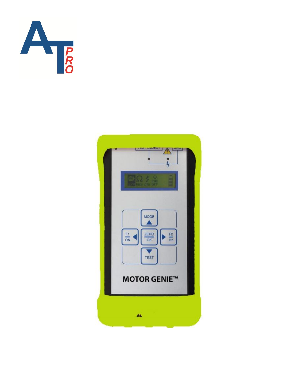
MOTOR GENIETM

©2016, ALL-TEST Pro, LLC Rev 2016-10
Table of Contents
I. Introduction.........................................................................................................3
II. Safety..................................................................................................................4
Instrument Warnings and Considerations............................................................4
General Safety Considerations.............................................................................4
Instrument Operation...........................................................................................5
Input Section....................................................................................................5
Display Section................................................................................................6
Indicator Light Section ....................................................................................6
Display Screen .................................................................................................6
Keypad Section................................................................................................8
Instrument Test Leads......................................................................................8
IV. Testing a Three Phase Induction Squirrel Cage Motor.............................9
Operating Procedure 3-Phase Motors..................................................................9
Winding Test........................................................................................................9
Turn the Instrument On..................................................................................10
Z/Test..........................................................................................................10
Observe/Record the Test Data .......................................................................10
Error Codes....................................................................................................11
Continue with Last Phase...............................................................................13
Resistance Test...............................................................................................15
Phase Balance Test ............................................................................................17
Insulation Resistance Testing ............................................................................20
Changing the Motor Test Frequency .................................................................22
V. Additional Functions and Features..............................................................23
Resetting the Unit ..............................................................................................23
Firmware Version ..............................................................................................23
VI. Charging the MOTOR GENIETM .................................................................24
VII. Data Interpretation Three Phase Motors..................................................25
Data Interpretation Tables..................................................................................25
Additional Data Interpretation Considerations Three Phase Motors.............25
Test Location .................................................................................................26
Confirming Suspected Winding Shorts .........................................................26
Method 1: Rotor Compensation.....................................................................26
Method 2: Variable Frequency Test ..............................................................27
IV. Available Accessories for the MOTOR GENIE™.....................................29
XI. Disclaimer, Copyright & Trademarks.........................................................31

MOTOR GENIETM User Manual
©2016, ALL-TEST Pro, LLC www.alltestpro.com Rev 2016-10
3
I. Introduction
The light-weight, hand-held instrument can be used for immediate detection of winding shorts,
insulation to ground faults, cable faults and more in low voltage 3 phase AC induction motors. Testing
can be performed at the motor connection box or motor control center hundreds of feet away.
The MOTOR GENIE™is designed to provide a simple test method for:
troubleshooting faults
commissioning new and rebuilt machines
verifying quality assurance in electric motors
The patented tests performed for early winding fault detection:
winding impedance test
phase angle (Fi)
current frequency response tests (I/F)
Phase to phase resistance: Unbalances in resistance are an indicator of loose connections, pitted
contactors, cold solder joints, etc.
Insulation Resistance to ground: To prevent electrical shocks and to assure safety of personnel the
MOTOR GENIE™provides an insulation to ground test. The insulation resistance test provides either
500 or 1,000 VDC to measure the insulation resistance up to 500 Meg-Ohm.

MOTOR GENIETM User Manual
©2016, ALL-TEST Pro, LLC www.alltestpro.com Rev 2016-10
4
II. Safety
CAUTION: MOTOR GENIETM is designed to test de-energized equipment safely and
quickly. Improper application of this instrument on live circuits is a danger to the user
and will result in the destruction of the testing circuit, requiring instrument replacement.
Instrument Warnings and Considerations
The MOTOR GENIETM is a CE registered instrument.
The following is a list of considerations for equipment life and accurate data collection:
Ensure that all power is removed from the circuit under test, including static power
stored in capacitors –Discharge all capacitors to be tested.
Attaching the MOTOR GENIETM to live voltage will destroy the unit and void the warranty.
Do not attempt to change the batteries. Contact your distributor of the MOTOR GENIETM, ALL-
replaced.
Do not open the instrument. Electrostatic charges may damage surface mount electronics. Please
contact your vendor or ALL-TEST Pro, LLC authorized repair center.
Use only the supplied charger for charging the instrument. It is an integral part of the charging
circuit. Using the wrong charger will damage your instrument.
General Safety Considerations
Following are general safety considerations for using the MOTOR GENIETM motor tester:
The MOTOR GENIETM is a de-energized (off-line) motor tester. All power and residual power
must be disconnected. It provides a safe method for testing your electric motors.
Follow all safety rules of your company and OSHA (or country equivalent) for de-energized testing
methods, including appropriate Personal Protective Equipment (PPE). Proper or safe operation of
the equipment is the sole responsibility of the user.
For MCA™testing, the MOTOR GENIETM sends out a low voltage, high frequency signal not
harmful to the technician or most electronic equipment (variable frequency drives and soft starts).
However, electronic equipment and personnel must observe appropriate safety considerations
(disconnect electronic equipment) when performing the insulation to Ground resistance test (Meg-
Ohm) test.

MOTOR GENIETM User Manual
©2016, ALL-TEST Pro, LLC www.alltestpro.com Rev 2016-10
5
III. MOTOR GENIETM Kit Components
Figure 1: MOTOR GENIETM Kit
The MOTOR GENIETM kit contains all of the necessary components necessary to test most electrical
machinery:
A. MOTOR GENIETM instrument
B. Batteries (installed)
C. Test leads and clips
D. Charger (115 or 230 Volt)
E. Manual (CD)
F. Carrying Pouch (Option)
Instrument Operation
The instrument is divided up into three working areas:
1. Input Section
2. Display Area
3. Keypad
Input Section
The input section provides all the external connections to the MOTOR GENIETM
A. Test lead port
B. Charger port
C. Ground test lead port for Insulation to Ground
Measurements
D. Reset Button
A
B
C
D
Parameter
Valid Test Range
Accuracy
Max
Resolution
Repeatability
Resistance
0.1 ~ 250 Ω
± 3%
10 mΩ
± 2%
Insulation
Resistance
0 ~ 100 MΩ
± 3%
0.01 MΩ
± 1%
100 ~ 500 MΩ
± 5%
Impedance
1 ~ 999 Ω
± 3%
10 mΩ
± 2%
Phase Angle (°)
15° ~ 90°
± 2°
1°
± 1°
I/F (%)
-50% ~ -15%
± 2 Digits
1 Digit
± 1 Digit

MOTOR GENIETM User Manual
©2016, ALL-TEST Pro, LLC www.alltestpro.com Rev 2016-10
6
Display Section
The display section is divided into 2 sections:
1. Indicator Lights
2. Display Screen
The Indicator Lights (section 1) informs the operator when an operation or test is being performed.
The Display screen (section 2) allows the operator to select tests to be performed by the instrument.
Indicator Light Section
1. Charging light –Indicates that the unit is charging, light is illuminated red while charging, light
is green when fully charged.
2. Test indicator light –Light is illuminated green when the unit is testing
3. Insulation Test indicator light –The light illuminates yellow when the instrument is testing
insulation resistance. Caution –Applied voltage is 500 or 1,000 Volts DC.
Display Screen
The display screen has individual icons to select and perform the various motor and winding tests.
1. Z/ψ Icon performs the Impedance (Z), Phase Angle (ψ), Current/Frequency (I/F) and Phase
Balance tests (used to identify developing winding faults).
2
1

MOTOR GENIETM User Manual
©2016, ALL-TEST Pro, LLC www.alltestpro.com Rev 2016-10
7
2. RES Icon performs the phase-to-phase Resistance (R) tests. (used to identify loose connections)
3. INS Icon performs the Insulation to ground resistance test (used to verify that the insulation to
ground resistance is sufficient to prevent electrical shock).
4. PWR OFF Icon turns the instrument off (it will automatically shut-off after about 5 minutes).
5. Firmware Version number can be displayed when the empty space to the right of PWR OFF
icon is pressed –see the highlighted part below.
6. Battery charge level indicator. A fully charged battery will have 7 bars (it is recommended to
keep the AT31 on charge when not in use to ensure proper operation).
MOTOR GENIETM User Manual
©2016, ALL-TEST Pro, LLC www.alltestpro.com Rev 2016-10
8
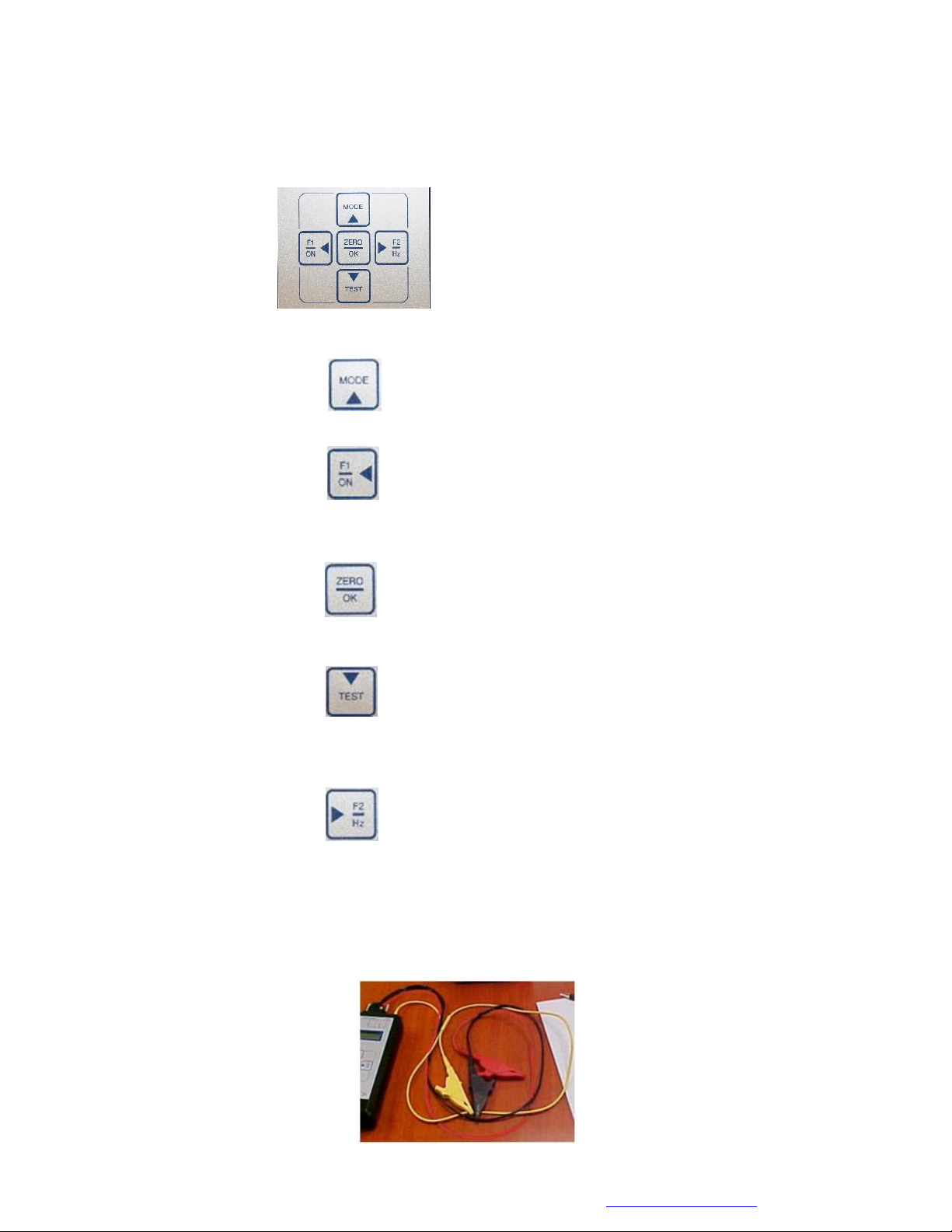
Keypad Section
The keypad section provides keys to operate and control the functions of the instrument.
1. Up direction and MODE key returns the display screen to the main menu.
2. F1/ON and Left direction key turns the instrument on and moves the curser across the display
screen toward the left.
3. ZERO /OK (Selection) key selects which test to perform and provides reference selection to
calculate % difference of the measured impedance value.
4. Down direction and TEST key toggles between display screens and performs selected tests.
5. Right direction and F2/Hz key allows the operator to change the test frequency for the winding
test and moves the cursor across the display screen to the right.
Instrument Test Leads
The MOTOR GENIETM uses a 15-pin DB connector for winding testing. The red test lead is the output
and the black test lead, is the return. For insulation testing, the yellow test lead should be connected to
ground.
MOTOR GENIETM User Manual
©2016, ALL-TEST Pro, LLC www.alltestpro.com Rev 2016-10
9
IV. Testing a Three Phase Induction Squirrel Cage Motor
Testing can be performed remotely from the motor control center, the motor disconnect or at the motor
itself. This instruction is provided to demonstrate all of the features of the MOTOR GENIETM, which
can also be used to evaluate other types of electric machines.
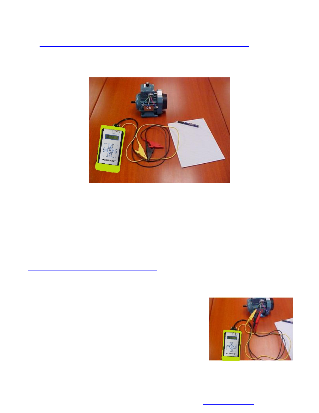
Figure 2: Equipment and Materials for Testing with the MOTOR GENIETM
To perform a motor test with the MOTOR GENIETM requires:
MOTOR GENIETM
Test leads and lead clips
A pen and paper (or a copy of the Motor Test Form on page 38).
Testing can be performed directly at the motor, at the nearest motor control center or disconnect. For
purposes of this manual, we will test at the motor using an M2002 training motor.
Operating Procedure 3-Phase Motors
Winding Test
Measures and displays the winding impedance (Z), Phase Angle (), Current Frequency response (I/F),
Resistance (R) and Impedance phase balance.
1. Label the three motor leads T1, T2, T3.
Note: It is very important to take the data in the same order
for long term trending.
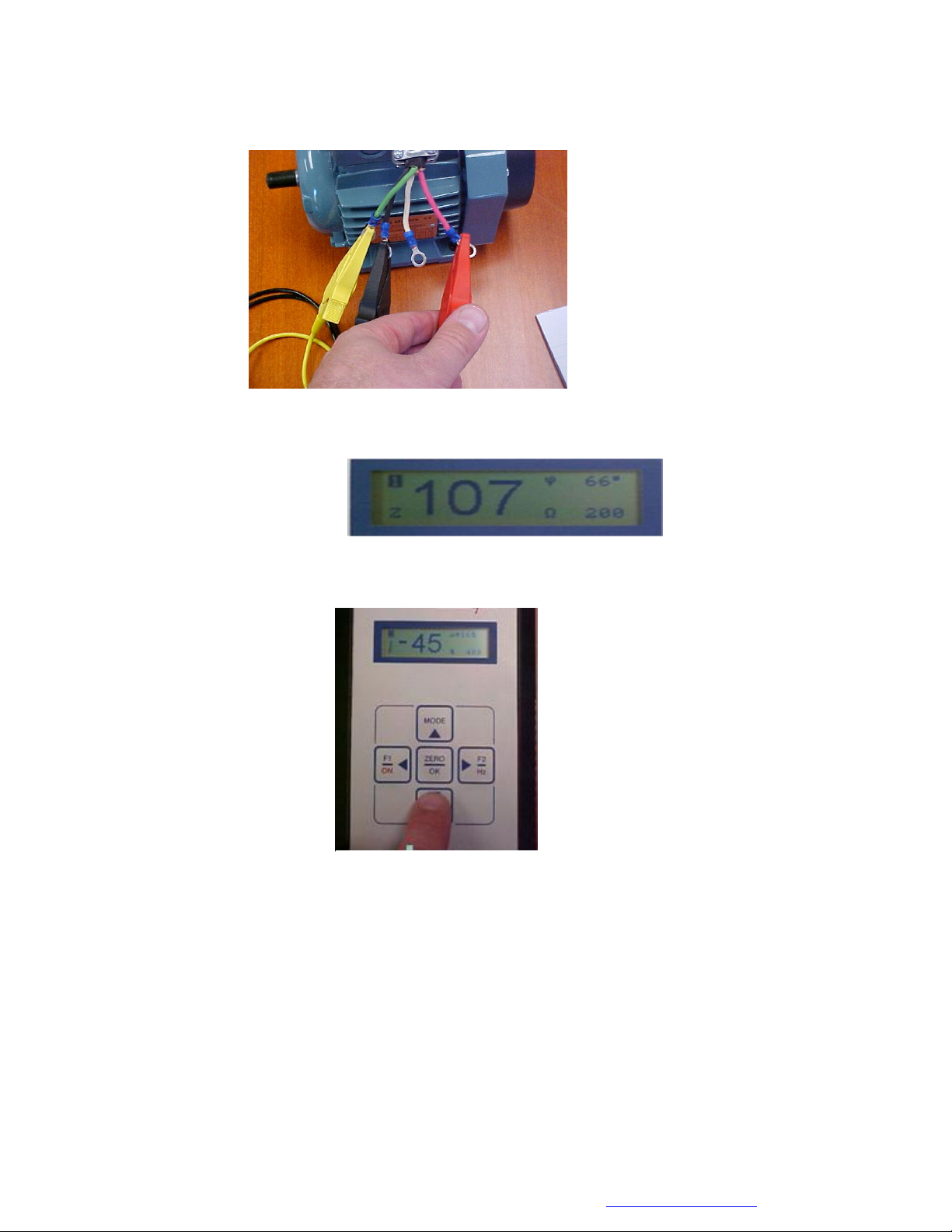
2. Connect the Test leads to the Motor leads T1 & T2.
Note: For quick trouble shooting the order of the readings is
not important. However, for long term trending of the data,
testing should be performed in the same order each time.
Optional: Connect the Yellow lead to ground, this is only required for measuring insulation to ground.
MOTOR GENIETM User Manual
©2016, ALL-TEST Pro, LLC www.alltestpro.com Rev 2016-10
10
Display Screen 1
Turn the Instrument On
Press and hold the F1/ON key for 1 to 3 seconds. This will bring up the main display screen.
Z/Test
1. Using the ◄F1 and ►F2, keys highlight the Z/test icon
2. Press the ZERO/OK Key to select the Winding Test icon (Z/)from the main menu.
Observe/Record the Test Data
1. The default value is 200 Hz, as displayed in the bottom right corner of the display screen.
a. The value of the impedance should be between 1 and 999 Ω. If the Z is less than 1 or
greater than 999 Ω change the test frequency of the winding test (see Changing the
Motor Test Frequency on page 22).
b. The current frequency response value (I/F) must be between -15 and -50, if it is not
change the frequency of the winding test.
c. If the phase angle (Fi) is less than 15°, change the winding test frequency.
Note: If any of the measurements fall outside the above ranges, the test is not valid.
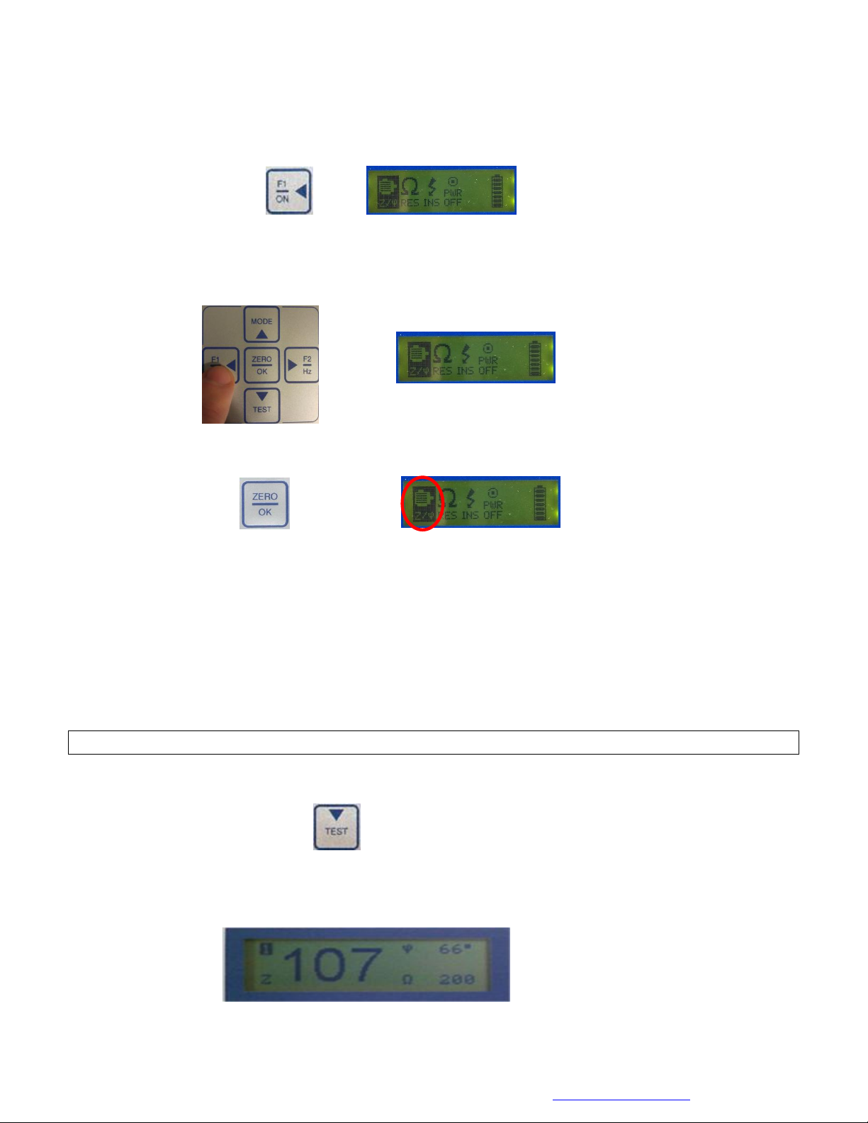
2. Display screen 2 displays the results of the current frequency test. To view display screen 2
Press the TEST key.
Display screen 1: Displays the measured impedance in ohms 107, phase angle in degrees 66°, and the
frequency of the winding test, 200 Hz. The screen number (1) is displayed in the upper left hand corner.
MOTOR GENIETM User Manual
©2016, ALL-TEST Pro, LLC www.alltestpro.com Rev 2016-10
11
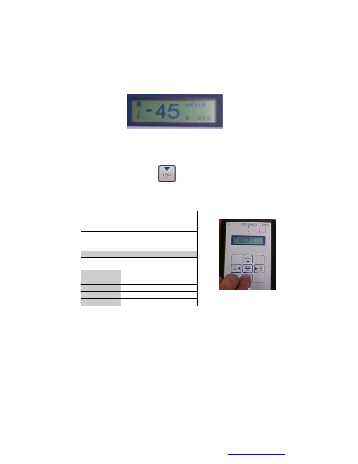
Display Screen 2: Displays the results of the Current Frequency (I/F) response test (-45), (the current at
400 Hz is 45% lower than the current at 200 Hz). The doubled test frequency is displayed in the lower
right hand corner; screen number (2) is displayed in the upper left hand corner. Note: The 16% shown
in upper right corner is the change in phase angle when the test frequency is doubled. Not used for
analysis purposes.
To return to the Display Screen 1 Press the TEST key again, this displays the impedance and phase
angle measurement.
3. Record the measured values on the Motor Test Form.
Error Codes
If the impedance readings are out of range an error code will be displayed on the measurement screen.
E1 error code means the impedance value is out of range, i.e. greater than 999 ohms but
less than 60,000 Ω.
--- means either the impedance or resistance value is over 60,000 Ω, or the test is invalid.
Continue with Other Phases
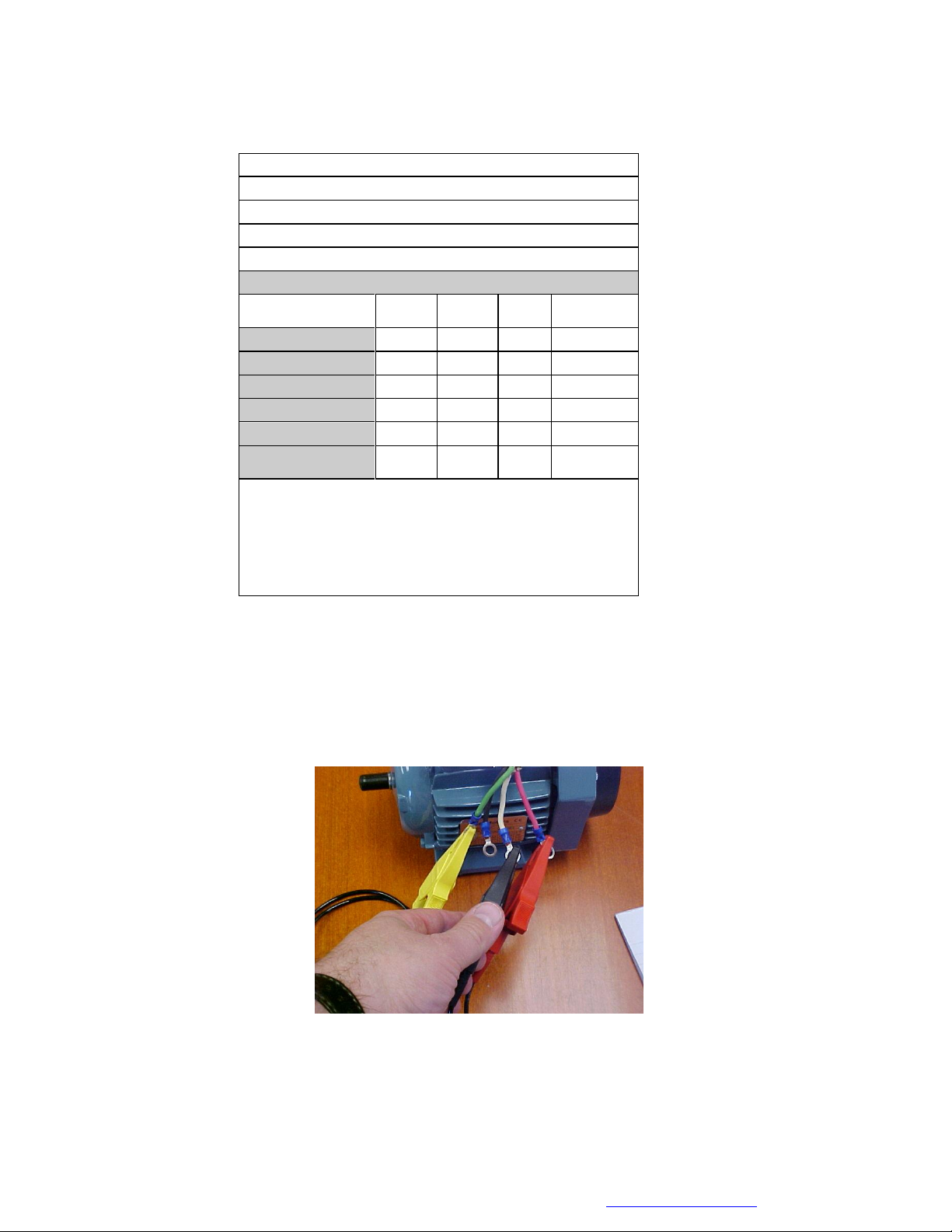
1. Move the test leads to T1 & T3 to make the measurements on the next phase.
MOTOR GENIETM Motor
Test Form
Motor ID:
Location:
Test Date:
Test Frequency
Phase
1-2
Phase
1-3
Phase
2-3
Impedance (Ω)
107
Phase Angle (°)
66
Z-Test or I/F
-45
Resistance (Ω)
Display Screen 2
MOTOR GENIETM User Manual
©2016, ALL-TEST Pro, LLC www.alltestpro.com Rev 2016-10
12
2. Read the Impedance (Z) and Phase Angle (ψ) values from display screen 1 for winding. Do not
fill in the phase balance until all three phases have been measured.
3. Depress the TEST key to display the Current Frequency Response (I/F).
Winding 2 Current
Frequency Response
MOTOR GENIETM User Manual
©2016, ALL-TEST Pro, LLC www.alltestpro.com Rev 2016-10
13
4. Record these test results on the Motor Test Form.
Continue with Last Phase
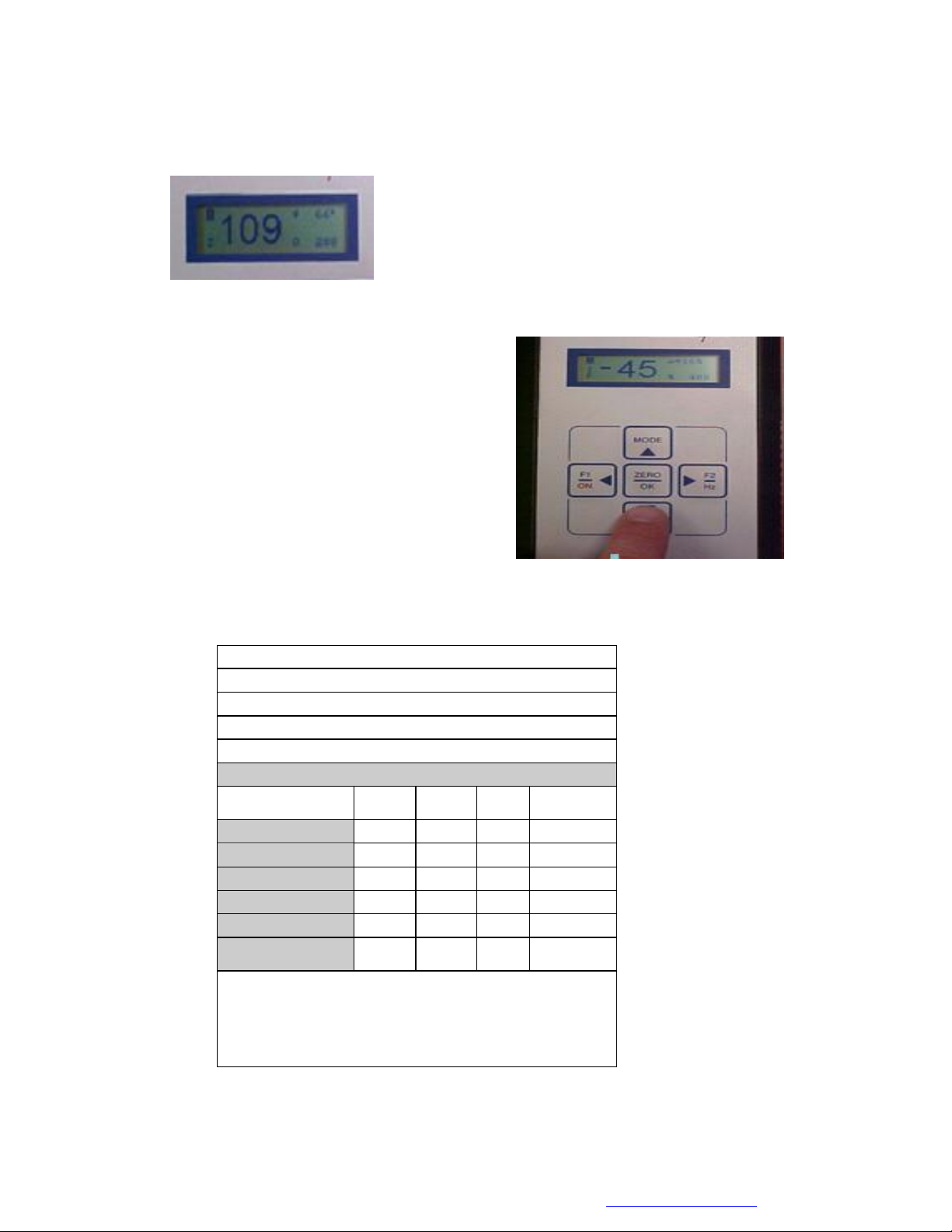
1. Move the Test Leads to T2 & T3
MOTOR GENIETM Motor Test Form
Motor ID:
Location:
Test Date:
Test Frequency
Phase
1-2
Phase
1-3
Phase
2-3
Impedance (Z)
107
107
Phase Angle (°)
66
66
Z-Test or I/F
-45
-45
Resistance (Ω)
Phase balance (opt)
Ins Resistance (M Ω)
Test
Voltage
Comments:
©2016 ALL-TEST Pro, LLC
MOTOR GENIETM User Manual
©2016, ALL-TEST Pro, LLC www.alltestpro.com Rev 2016-10
14
2. Read the Impedance (Z) and Phase Angle (ψ) values from display screen 1 for winding. Do
not fill in the phase balance until all three phases have been measured.
3. Press the TEST key to display the Current Frequency Response (I/F).
4. Record these test results on the Motor Test Form.
MOTOR GENIETM Motor Test Form
Motor ID: Test Motor
Location: Warehouse
Test Date: 8/8/16
Test Frequency 200 Hz
Phase
1-2
Phase
1-3
Phase
2-3
Impedance (Z)
107
107
109
Phase Angle (°)
66
66
66
Z-Test or I/F
-45
-45
-45
Resistance (Ω)
Phase balance (opt)
Ins Resistance (M Ω)
Test
Voltage
Comments:
©2016 ALL-TEST Pro, LLC
Winding 3 Current Frequency
MOTOR GENIETM User Manual
©2016, ALL-TEST Pro, LLC www.alltestpro.com Rev 2016-10
15
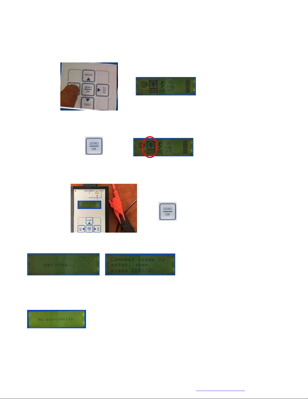
Resistance Test
1. Using the ◄F1 and ►F2, keys to highlight the REStest icon
2. Press the ZERO/OK Key to select the resistance test icon (RES) from the main menu
3. The screen instruction reminds users to short the two test leads. Then press ZERO/OK Key.
4. Wait until “zeroing …” disappears and the right screen below shows up.
Note: for poor connection or no connection, the following screen will show up for a couple of seconds
and resume to the right screen above. In such case, please check the connections and press ZERO/OK
key again. No continuity means the circuit is open.

MOTOR GENIETM User Manual
©2016, ALL-TEST Pro, LLC www.alltestpro.com Rev 2016-10
16
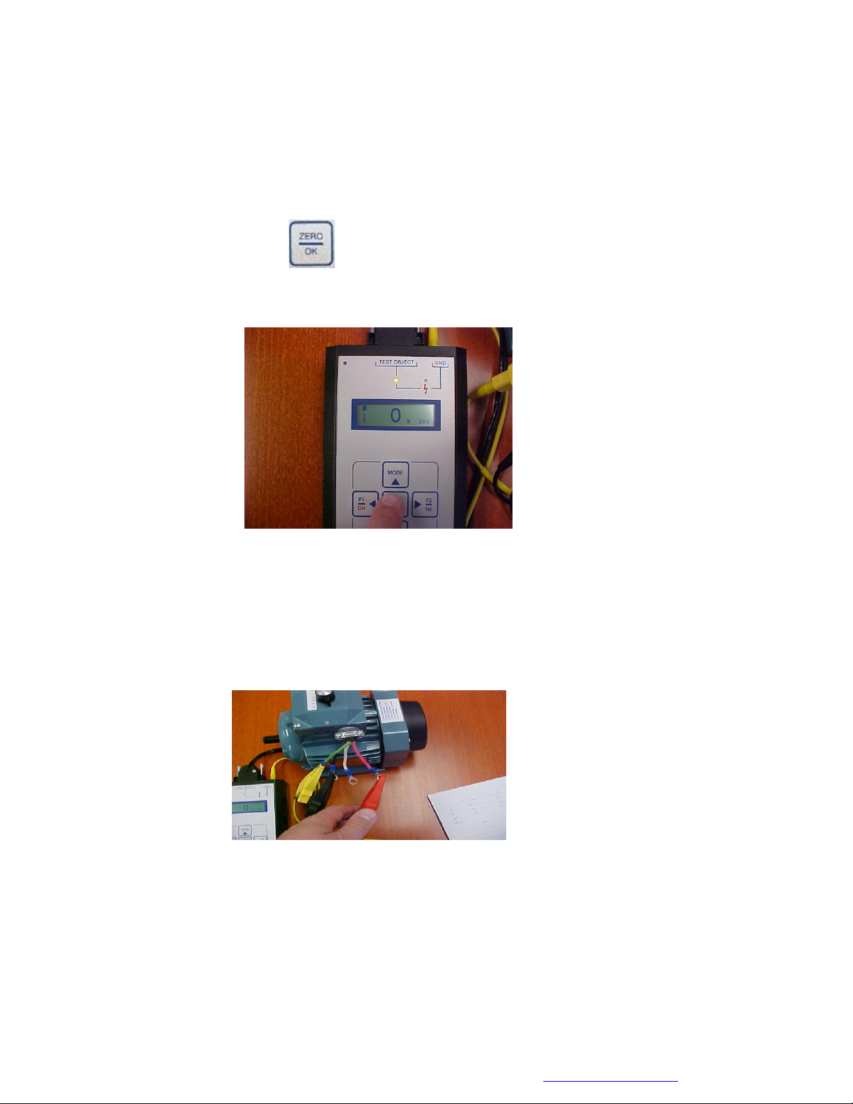
5. Connect the two test leads to the motor terminals T1 & T2, press ZERO/OK Key, the measuring
screen shows up as the left screen below, then the resistance result will be displayed. An example is
shown below.
Note: the following error codes may show up in certain situations. Please refer to the Section “Error
Codes” below – “E 1” means resistance is over 999 Ω but below approximately 60,000 Ω. “- - -”
means either the resistance is over 60,000 Ω or the test is invalid. The valid resistance measurement
range is 100 mΩ ~ 250 Ω(0.1 to 250 Ω). Any measurement below 0.1 Ω should be verified using a low
resistance ohmmeter.
6. Connect the two test leads to the motor terminals T1&T3 and perform another resistance test by
pressing ZERO/OK Key. In the same way, test the resistance on the other two terminals T2 & T3.
Record all test results on the Motor Test Form.
7. To exit to the main menu, press the MODE key.
Note: To make resistance measurement again, repeat Steps 1 ~ 7 above.
MOTOR GENIETM Motor Test Form
Motor ID: Test Motor
Location: Warehouse
Test Date: 8/8/06
Test Frequency 200 Hz
Phase
1-2
Phase
1-3
Phase
2-3
Impedance (Z)
107
107
109
Phase Angle (°)
66
66
66
Z-Test or I/F
-45
-45
-45
Resistance (Ω)
17.3
17.6
17.1
Phase balance (opt)
Ins Resistance (M Ω)
Test
Voltage
Comments:
©2016 ALL-TEST Pro, LLC

MOTOR GENIETM User Manual
©2016, ALL-TEST Pro, LLC www.alltestpro.com Rev 2016-10
17
Phase Balance Test
This calculates the impedance unbalance between phases. This value can be used to relate energy,
reliability and production-cost avoidance potential to electric motor systems impedance unbalance. The
Impedance Unbalance Calculator (IUC) is available from ALL-TEST Pro. The concept of the IUC
comes from Keeping the Spark in Your Electrical System: An Industrial Electrical Distribution
Maintenance Guidebook published by the US Department of Energy, Bonneville Power Administration,
Pacific Gas & Electric, PacifiCorp and Tacoma Public Utilities. As impedance varies with each phase,
the current in each leg of the motor varies. This generates increased losses in the form of heat. Heat
reduces both insulation life and the life of the lubricant.
(The Impedance Unbalance Calculator is available from ALL-TEST Pro, LLC).
1. Turn the instrument on, and place the test leads on any 2 motor leads, for discussion purposes
use T2 & T3.
2. Select the Z/option and rotate the motor shaft until the maximum impedance value is reached.
Record the value.
MOTOR GENIETM User Manual
©2016, ALL-TEST Pro, LLC www.alltestpro.com Rev 2016-10
18
3. Perform the same Z/test on the other two phases.
4. Select the phase with the highest maximum impedances (for discussion purpose, assuming it is
Phase T2-T3). Rotate the shaft to find the rotor position where the maximum impedance occurs.
5. Then press the ZERO key to set the reference phase (T2-T3) to zero. Enter a zero
for phase (T2-T3) on the Motor Test Data form.
6. Move the Test leads to T1 & T3. Turn the motor shaft slowly until the minimum % difference is
obtained. Record this number on the Motor Test Data form.
Note: The percentage should be less than 3% of phase unbalance. A percentage > 5% indicates a
fault in the winding and should be investigated further

MOTOR GENIETM User Manual
©2016, ALL-TEST Pro, LLC www.alltestpro.com Rev 2016-10
19
7. Again move the Test leads to T1 & T2. Turn the motor shaft slowly until the minimum %
difference is obtained. Record this number on the Motor Test Data form.
MOTOR GENIETM Motor Test Form
Motor ID: Test Motor
Location: Warehouse
Test Date: 8/8/16
Test Frequency 200 Hz
Phase
1-2
Phase
1-3
Phase
2-3
Impedance (Z)
107
107
109
Phase Angle (°)
66
66
66
Z-Test or I/F
-45
-45
-45
Resistance (Ω)
17.3
17.6
17.1
Phase balance (opt)
2
0
0
Ins Resistance (M Ω)
Test
Voltage
Comments:
©2016 ALL-TEST Pro, LLC
MOTOR GENIETM User Manual
©2016, ALL-TEST Pro, LLC www.alltestpro.com Rev 2016-10
20
Insulation Resistance Testing
To prevent electrical shocks and to assure safety of personnel the MOTOR GENIETM provides an
insulation to ground test. The insulation resistance test provides either 500 or 1,000 VDC, to measure the
insulation resistance up to 500 Meg-Ohm.
NOTE: Guidelines for test voltages are presented in the Table below. Readings of insulation resistance
are taken after the test voltage has been applied for 1 min. If these values differ from your equipment
manufacturers, follow their guidelines.
Insulation Resistance Test Voltage
Insulation Resistance Values (IEEE 43-2013)
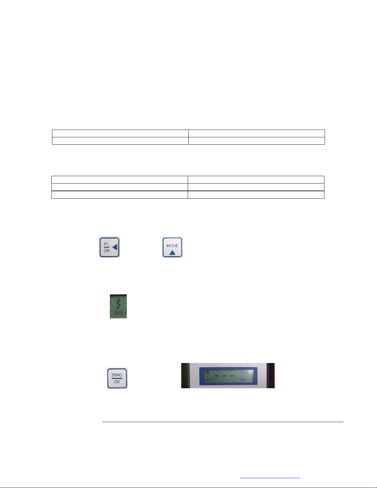
1. Using the ON key or the MODE key from the keypad section to navigate to the display screen
(This is the main menu).
2. Use the ◄►to highlight the INS icon from the display screen. This sets the instrument up to
measure insulation resistance to ground.
3. Connect both the Red lead & the Yellow lead to ground.
4. Press the ZERO/OK key to select the Insulation Resistance Test. This displays screen 8, the
insulation resistance test screen.
5. View the insulation test voltage selected (upper right hand corner of the insulation resistance
display screen). Refer to the insulation resistance test voltage table above for the correct voltage.
Motor Voltage Rating
Insulation Test Voltage
< 1000 Volts AC
500 V
Application
Pass/Fail Value
Insulation systems prior to 1970
> 1 Meg-Ohm + 1 Meg-Ohm per kV rating of motor
Random Wound motors less than 600 V
> 5 Meg-Ohms
Table of contents
Popular Test Equipment manuals by other brands


Listen
Listen AmpConnect ISC quick start guide

Humboldt
Humboldt Deluxe Series product manual

MULTI MEASURING INSTRUMENTS CO.,LTD.
MULTI MEASURING INSTRUMENTS CO.,LTD. ALCL–40H instruction manual

AquaViva
AquaViva POOL LAB 1.0 user manual

TSI Instruments
TSI Instruments Certifier Plus user manual

Sanwa
Sanwa SH-88TR instruction manual


