v
Contents
Warranty............................................................................................................................................................iii
Contents.............................................................................................................................................................v
CHAPTER 1 Introduction and Parts Identification ................................................................................... 1-1
Introduction...........................................................................................................................................1-1
Interface Module................................................................................................................................1-1
High Flow Module..............................................................................................................................1-1
Low Flow Module...............................................................................................................................1-1
Oxygen Sensor..................................................................................................................................1-1
List of Standard Components ...............................................................................................................1-2
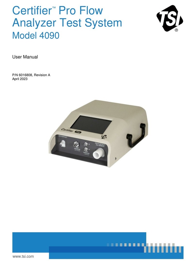
CertifierPlus High Flow Test System, Standard Kit (Model 4080-S).............................................1-2
CertifierPlus High Flow Test System, Full Kit (Model 4080-F)......................................................1-3
List of Accessory Kits............................................................................................................................1-4
CertifierPlus Low Flow Module Kit (Model 4082)..........................................................................1-4
CertifierOxygen Sensor Kit (Model 4073).....................................................................................1-4
Mounting Kit, for CertifierPlus Interface Module (PN 130398)......................................................1-4
Mounting Kit, for CertifierPlus Interface and Flow Module (PN 130399)......................................1-5
CertifierConnector Kit (PN 130391)..............................................................................................1-5
Flow Resistor Kit (PN 130395) ..........................................................................................................1-5
Other Optional Accessories..................................................................................................................1-6
CHAPTER 2 Flow Analyzer Overview ........................................................................................................ 2-1
Instrument Overview.............................................................................................................................2-1
4089 Interface Module, Back.............................................................................................................2-1
4089 Interface Module, Front.............................................................................................................2-1
4081 High Flow Module, Back...........................................................................................................2-2
4081 High Flow Module, Front...........................................................................................................2-2
4082 Low Flow Module......................................................................................................................2-2
Operation Overview..............................................................................................................................2-3
Flow Modules.....................................................................................................................................2-3
End Caps...........................................................................................................................................2-3
Lithium Ion Batteries..........................................................................................................................2-3
Supplying Power................................................................................................................................2-3
Power Button LED States..................................................................................................................2-3
Touchscreen Display.........................................................................................................................2-4
User Configurations...........................................................................................................................2-4
Data Acquisition and Export ..............................................................................................................2-4
USB Communications........................................................................................................................2-4
Measurements and Units......................................................................................................................2-5
Available Measurement Parameters .................................................................................................2-5
Available Units of Measurement........................................................................................................2-6
Measurement Parameter Definitions.................................................................................................2-7
CHAPTER 3 Flow Analyzer Setup .............................................................................................................. 3-1
Getting Started......................................................................................................................................3-1
Power On/Off.....................................................................................................................................3-1
Initialization and Warm-Up.................................................................................................................3-1
Instrument Setup...................................................................................................................................3-1
Connect/Disconnect Flow Modules ...................................................................................................3-1
Connect Inlet Filter.............................................................................................................................3-1
Connect the Low Pressure Measurement.........................................................................................3-2
