All Weather Inc AWOS 3000 User manual

Installation
and
Checkout
Manual
3000-017
Rev.C
Automated Weather Observing System
All Weather Inc. • 1165 National Drive • Sacramento, CA 95834 • USA • 800.824.5873 • www.allweatherinc.com
×
FAA APPROVED
ECP180 — 2011 May 5
NOT FAA APPROVED

Copyright © 201, All Weather, Inc.
All Rights Reserved. The information contained herein is proprietary and is provided solely for the
purpose of allowing customers to operate and/or service All Weather, Inc. manufactured equipment
and is not to be released, reproduced, or used for any other purpose without written permission of All
Weather, Inc.
Throughout this manual, trademarked names might be used. Rather than put a trademark (™) symbol in
every occurrence of a trademarked name, we state herein that we are using the names only in an editorial
fashion and to the benefit of the trademark owner, and with no intention of infringement. All Weather,
Inc. and the All Weather, Inc. logo are trademarks of All Weather, Inc.
Disclaimer
The information and specifications described in this manual are subject to change without notice.
Latest Manual Version
For the latest version of this manual, see the Product Manuals page under Reference on our web site at
www.allweatherinc.com/.
All Weather, Inc.
1165 National Drive
Sacramento, CA 95834
Tel.: (916) 928-1000
Fax: (916) 928-1165
Contact Customer Service
• Phone support is available from 8:00am - 4:30pm PT, Monday through Friday. Call 916-928-1000
and ask for “Service.”
• Online support is available by filling out a request at www.allweatherinc.com/customer/support.html

CONTENTS AWOS 3000 INSTALLATION AND CHECKOUT
i
Table of Contents
1. USING THIS MANUAL.........................................................1
1.1General Precautions.......................................................1
2. CENTRAL DATA PROCESSOR..........................................2
2.1CDP Installation..............................................................3
2.2CDP Rack Layout............................................................5
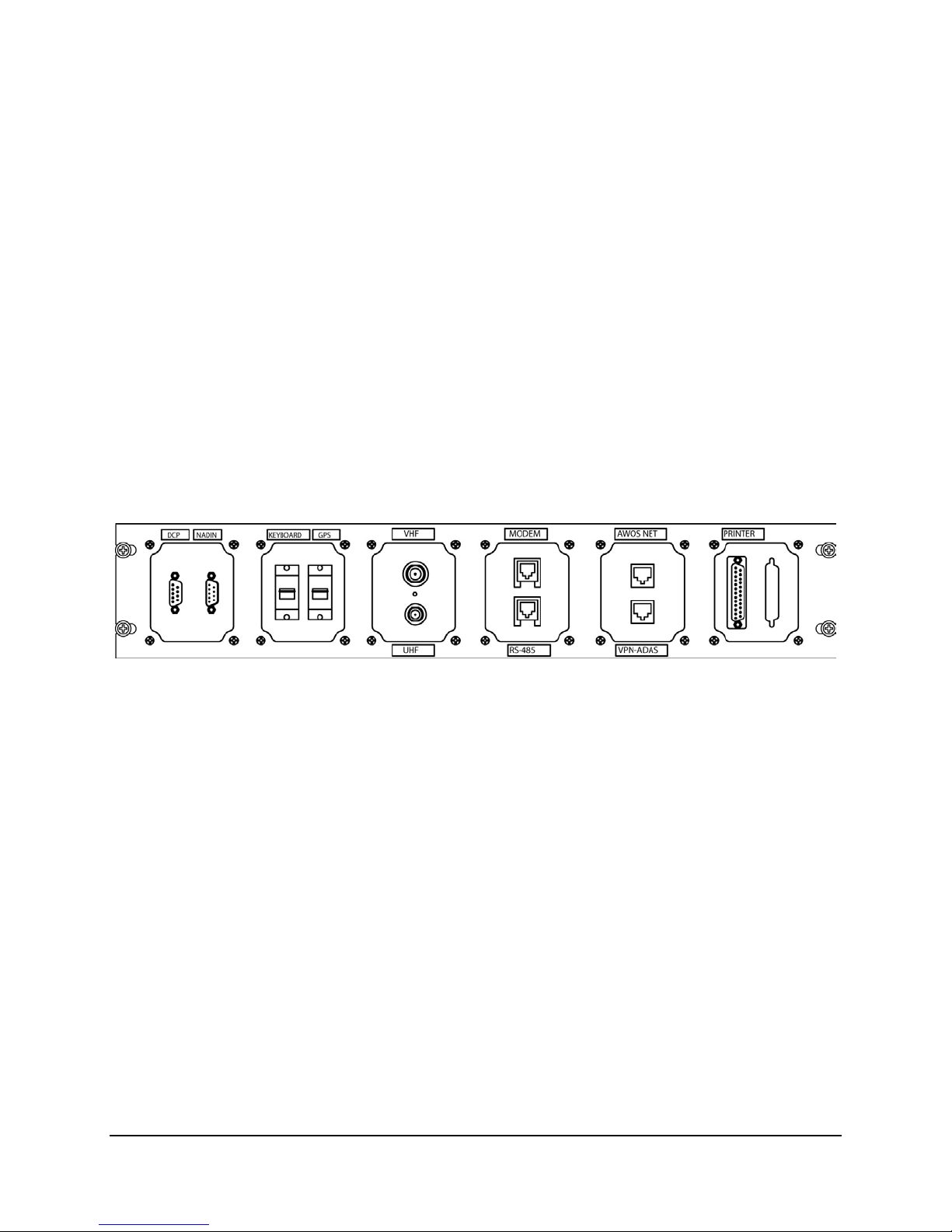
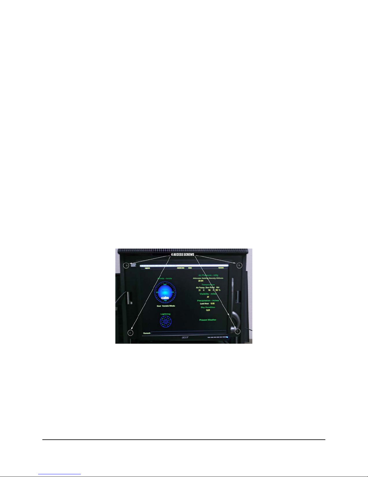
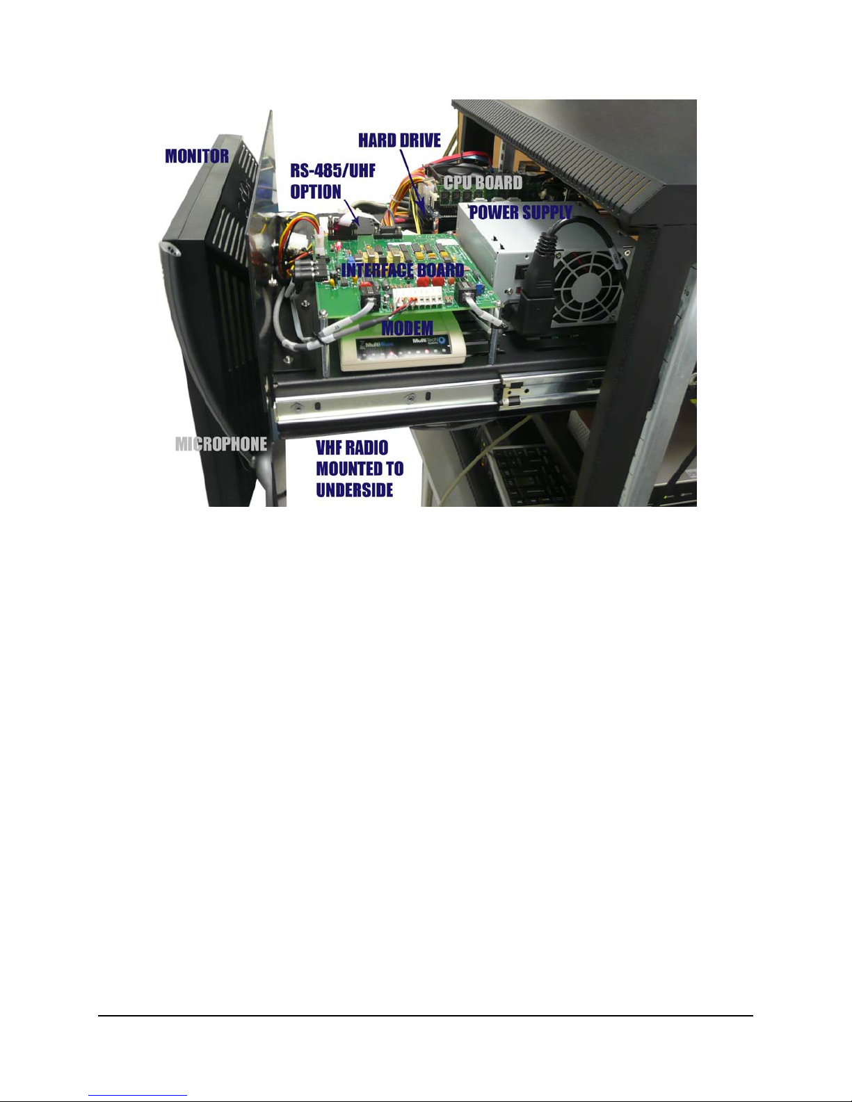
2.3CDP Top-Shelf Components...........................................5
2.4CDP Bottom-Shelf Components...................................12
2.5GPS NTP Time Standard..............................................15
2.6NADIN Interface Connection.........................................15
2.7Remote Displays Using AWOS Net..............................16
2.8KVM Extender for Remote Operation...........................22
2.9AWOS/ATIS Interface...................................................33
2.10CDP Checkout..............................................................38
2.11CDP Block Diagram......................................................39
3. DATA COLLECTION PLATFORM.....................................41
3.1DCP Mounting...............................................................41
3.2Sensor Wiring................................................................41
3.3Auxiliary Sensor Wiring.................................................42
3.4+5 V Power ...................................................................42
3.5-5 V Power....................................................................42
3.6Communication Connections........................................42
3.7RS-485 Expansion Port ................................................43
3.8Serial Sensor Wiring.....................................................43
3.9AC Power Wiring...........................................................43
3.10DC, Battery Backup, and Solar Power Wiring...............44
3.11+15 V DC Power Input..................................................44
3.12Battery Power................................................................44
3.13Solar Power...................................................................44
3.14DIP Switches.................................................................45
3.15DCP Checkout..............................................................46
4. MODEL 7190 DUAL DIGITAL BAROMETER ...................47
4.1Installation.....................................................................47
4.2Checkout.......................................................................48
5. MODEL 2020 MICRO RESPONSE WIND VANE..............50
5.1Installation.....................................................................50
5.2Checkout.......................................................................52
6. MODEL 2030 ANEMOMETER...........................................55
6.1Installation.....................................................................55
6.2Checkout.......................................................................56
7. MODEL 2040 ULTRASONIC WIND SENSOR..................58
7.1Installation Guidelines ..................................................58
7.2Mounting.......................................................................58
7.3Wiring...........................................................................60
7.4Checkout......................................................................62
8. MODEL 5190 TEMPERATURE/RH SENSOR...................63
8.1Installation....................................................................63
8.2Checkout......................................................................64
9. MODEL 8190 MOTOR ASPIRATED RADIATION SHIELD66
9.1MARS Installation.........................................................66
9.2Probe Installation..........................................................66
9.3Checkout......................................................................67
10. MODEL 6021 TIPPING-BUCKET RAIN GAUGE............68
10.1Siting.............................................................................68
10.2Installation....................................................................68
10.3Checkout......................................................................69
11. MODEL 8364-E VISIBILITY SENSOR ............................70
11.1Sensor Siting................................................................70
11.2Visibility Sensor Installation..........................................71
11.3Visibility Control Board Installation...............................72
11.4Power Connection........................................................73
11.5Ground Cable Installation.............................................73
11.6Signal Connections.......................................................74
11.7Additional Kits...............................................................75
11.8Checkout......................................................................76
12. MODEL 8339 CEILOMETER...........................................79
12.1Unpacking.....................................................................79
12.2Installation....................................................................80
12.3Checkout......................................................................84
13. MODEL 6490 PRESENT WEATHER SENSOR..............85
13.1Siting and Installation Guidelines.................................85
13.2Mechanical Installation.................................................86
13.3Electrical Installation.....................................................88
13.4Checkout......................................................................91

CONTENTS AWOS 3000 INSTALLATION AND CHECKOUT
ii
14. MODEL 6500 THUNDERSTORM/LIGHTNING SENSOR91
14.1 Overview.......................................................................91
14.2 RFI/EMI Precautions.....................................................91
14.3 Sensor Installation.........................................................92
14.4 Checkout.......................................................................95
15. MODEL 6495 FREEZING RAIN SENSOR.......................96
15.1 Mechanical Installation..................................................96
15.2 Power Connections.......................................................97
15.3 Data Connections..........................................................97
15.4 Checkout.......................................................................97
16. FOLDOVER TOWER OPERATIONS...............................98
16.1 Lowering the Tower.......................................................98
16.2 Raising the Tower.........................................................98
17. DRAWINGS......................................................................99

USING THIS MANUAL
1
Using This Manual
This manual details installation and checkout procedures for the All Weather, Inc. Automated
Weather Observing System (AWOS) 3000. The AWOS 3000 is available in multiple configura-
tions, with each AWOS configuration having a unique suite of sensors. This manual is organized
around the individual sensors, with each sensor covered in its own chapter. A table at the
beginning of each chapter lists the AWOS configurations that include the sensor.
The first two chapters cover installation and checkout of the Central Data Processor (CDP) and
Data Collection Platform (DCP), which are included in all systems. The remaining chapters
cover the installation of the sensors and their accessories.
Detailed installation drawings and wiring diagrams are provided in Chapter 17, Drawings.
Checkout procedures are provided for each sensor or component. These are intended to verify
operation when a sensor or component is replaced in an existing system. When a complete
system is installed, checkout is accomplished by performing the Annual System Revalidation
procedure described in the AWOS 3000 Maintenance Manual (3000-027).
1.1 General Precautions
Note that ultraviolet-resistant cable ties must be used whenever cable ties are called for.
Note that the metallurgy of the stainless U-bolts will cause the nuts to seize to the U-bolts and
twist them off. Lubricate the threads with anti-seize compound before assembling.
Electrostatic discharge (ESD) precautions must be followed when working with printed circuit
boards and wiring the data interfaces. At a minimum, wear a grounding wrist strap and connect
the ground to a chassis ground inside the enclosure you are working in.
Observe basic electrical safety procedures such as turning the power or circuit breaker off when
working with the AC power interfaces.
All test and calibration equipment must be traceable as specified by the National Institute of
Standards or other standards organizations where specified.
Chapter
1

CENTRAL DATA PROCESSOR
2
Central Data Processor
AWOS
A AWOS
AV AWOS
I AWOS
II AWOS
III AWOS
IIIP AWOS
IIIT AWOS
IIIPT AWOS
IIIPTZ
CDP
The Central Data Processor (CDP) is mounted in an industrial-grade rack (Figure 1) along with
an Uninterruptible Power Source (UPS), VHF ground-to-air radio, voice/RMM (Remote Main-
tenance Monitoring)) modem, and any of the CDP options. The available options include UHF
data link radio, AWOS Net, and AWOS/ATIS Interface.
Figure 1. AWOS 3000 CDP Rack
Chapter
2

CENTRAL DATA PROCESSOR AWOS 3000 INSTALLATION AND CHECKOUT
3
2.1 CDP Installation
The CDP is self-contained. It is installed indoors, at a location with access to AC power and any
auxiliary communication and data lines required. Installation of the CDP primarily involves
routing external cables into the CDP rack and connecting them to the CDP back panel. The
installation of individual CDP options (AWOS Net, UHF Radio, etc.) is covered later in this
chapter in the sections devoted to those options.
The CDP is a 22" × 20.5" × 20" 11RU small equipment rack that weighs 138 pounds. The CDP
must be place in a stable location for its size and weight.
Drawing 3000-019 in Chapter 17, Drawings provides the CDP wiring diagram for reference.
2.1.1 Back-Panel Connections
Connections to external devices and data sources (such as the AWOS DCP, ADAS, GPS NTP
server, and printer), as well as internal components (such as VHF Radio and Modem) are made
at the back panel. The back panel is located inside the CDP rack, just above the bottom shelf (see
Figure 8). Figure 2 shows the back panel connectors.
Figure 2. CDP Back Panel Connectors (front end)
External cables are routed to the back panel through an access hole located in the right rear
corner at the top of the rack enclosure.
2.1.2 Connecting Power
Power is supplied to the CDP through the UPS housed in the base of the CDP rack. A power
cord is included and installed, and is routed through the access hole in the top of the CDP
enclosure. Connect this power cord to a suitable AC outlet.
2.1.3 Connecting the VHF Antenna
The VHF antenna and antenna cable must be installed. A mast for the antenna should have been
installed as part of the site preparation. The cable from the VHF Ground-to-Air (GTA) radio
antenna must be routed to the CDP rack and connected to the back panel.
1. Using the radiator length chart on the UHF/VHF Antenna Assembly instructions
(included with the VHF antenna and also in Chapter 17, Drawings), find the optimum
radiator length for the VHF radio frequency.
Note that the radiator lengths remain unchanged from the provided length for standard
VHF GTA frequencies used for AWOS systems.

CENTRAL DATA PROCESSOR AWOS 3000 INSTALLATION AND CHECKOUT
4
2. Using a hacksaw, trim the radial length of the antenna (Part M489103) to the length
specified. Cover the end of the radiator with the plastic end cap provided with the
antenna.
3. Coat the threaded ends of the radials with PTFE lubricant (supplied with antenna). Attach
the radials to the radiator section.
4. Coat the threaded portion of the U-bolt with PTFE. Attach the U-bolt to the antenna as
shown.
5. Coat the threaded portion of the radiator with PTFE. Attach the completed antenna to the
U-bolt mount as shown.
6. Attach the antenna to the mast installed on the building for the VHF radio antenna.
7. Attach the VHF radio antenna cable (Part M491361) UHF connector to the antenna.
8. Route the antenna cable to the CDP location.
9. Do not trim the antenna cable before you attach the BNC connector to the antenna cable
since shorter antenna cable lengths mean less signal loss, and this translates to an
increased effective radiated power by the antenna, which may then exceed regulatory
specifications. Figure 3 shows how to attach the BNC connector to the antenna cable.
10. Connect the cable to the BNC connector labeled VHF on the front side of the back panel.
Figure 3. BNC Connector Installation

CENTRAL DATA PROCESSOR AWOS 3000 INSTALLATION AND CHECKOUT
5
2.1.4 Connecting Optional Printer
A parallel port is available on the CDP back panel for connection to a printer. Connect the printer
as follows:
1. Connect the Centronics 36 end of the parallel printer cable (Part 20912-A) to the printer
cable connector on the printer.
2. Feed the printer cable through the access hole in the top of the CDP enclosure.
3. Connect the other end of the printer cable to the DB25 connector labeled PRINTER on
the front side of the back panel.
2.2 CDP Rack Layout
The CDP components are housed on two shelves inside the rack’s lockable enclosure. The
shelves can be accessed via the front door or either of the side doors. The easiest entry point will
depend on the component being accessed.
2.3 CDP Top-Shelf Components
The top shelf (Figure 5) is attached to the back of the CDP monitor and contains the CPU/Hard
Drive assembly, Power Supply, Interface Board, Voice Modem, and communication option
(RS-485 converter or UHF radio). The shelf is accessed by removing four screws from the
corners of the front panel (see Figure 4) and sliding the entire shelf, including the monitor,
forward.
Figure 4. Front Panel Screws

CENTRAL DATA PROCESSOR AWOS 3000 INSTALLATION AND CHECKOUT
6
Figure 5. CDP Top-Shelf Components
2.3.1 Communications
The communication options—RS-485 converter or UHF radio—mount to the CDP top shelf in
front of the CPU Board/Hard Drive assembly.
2.3.1.1 RS-485 Landline Converter Installation
When an RS-485 landline is used for communicating with the DCP, an RS-485 converter is
installed on the top shelf using Velcro.
The RS-485 converter kit includes:
• M417210-00 RJ-11 terminal box
• M438205-00 RS-485 converter
• M491860-00 serial cable
• M491848-00 power cable
• M491851-00 RS-485 to panel cable
• M491861-00 RJ-11 cable
• Velcro

CENTRAL DATA PROCESSOR AWOS 3000 INSTALLATION AND CHECKOUT
7
The following steps describe how to install the RS-485 converter kit. Figure 6 illustrates the
connections.
1. Power off the CDP.
2. Affix one side of the Velcro backing to the underside of the converter. Attach the other
side of the Velcro backing to the top shelf so that the converter is located at the front-left
of the shelf with sufficient clearance from other components (see Figure 5).
3. Connect the male end of the DB9 connector on cable M491860-00 to the RS-485
converter’s female DB9 connector.
4. Connect the other end of the cable to the DCP connector on the back panel (see Figure 6).
This connection will be modified if the AWOS Net option is installed (see Section 2.4.1.1).
5. Connect the M491848-00 power cable’s yellow wire to the V+ connector on the converter.
6. Connect the power cable’s black wire to the 0V- connector on the converter.
7. Connect the other end of the power cable to the mating connector on the CDP power
supply’s unused power cable.
8. Connect the M491851-00 RS-485 cable to the converter as follows:
• Red wire to D+ terminal on the converter.
• Green wire to D- terminal on the converter.
• Black wire to GND terminal on the converter.
9. Connect the RJ-11 connector end of the RS-485 cable to the back of the RS-485 RJ-11
jack on the back panel (see Figure 2, Figure 6, and Figure 8).
10. If the RS-485 cable from the DCP is already terminated in an RJ-11 jack, which is likely to
be in a wall-mounted terminal box close to the CDP rack, use the M491861-00 RJ-11 cable
to connect to this jack, then feed the cable through the top of the rack and connect the other
end to the front of the RS-485 jack on the CDP back panel. This completes the installation.
If there is no wall-mounted terminal box, use the M417210-00 RJ-11 terminal box in-
cluded with the RS-485 converter kit. Try to install the M417210-00 RJ-11 terminal box
within 3 feet (1 meter) of the CDP rack on a convenient surface using the two mounting
screws that are included. Use the fork lugs provided to terminate the wires from the DCP.
Although the wires from the DCP may have various colors, the corresponding signals
must be matched with the specified colors inside the terminal box.
• Connect the RS-485(+) wire to the screw terminal associated with the red wire.
• Connect the RS-485(-) wire to the screw terminal associated with the green wire.
• Connect the RS-485 ground wire to the screw terminal associated with the black
wire.
Now you may connect the M491861-00 RJ-11 cable as described at the start of this step.

CENTRAL DATA PROCESSOR AWOS 3000 INSTALLATION AND CHECKOUT
8
Figure 6. RS-485 Landline Converter Installation

CENTRAL DATA PROCESSOR AWOS 3000 INSTALLATION AND CHECKOUT
9
2.3.1.2 UHF Radio Installation
When a radio data link is used between the DCP and the CDP, a UHF radio is mounted to the top
shelf. The UHF antenna connects to the BNC connector labeled UHF on the back panel, The
radio mounts to the shelf using Velcro.
The radio kit includes:
• Model 20980-A UHF Radio
• M491860-00 serial cable
• M491847-00 power cable
• M491852-00 antenna cable
• Velcro
The following steps describe how to install the radio kit. Figure 7 illustrates the connections. See
also in Chapter 17, Drawings, for additional information about the antenna and mast assembly
and installation.
1. Power off the CDP.
2. Affix one side of the Velcro backing to the underside of the UHF radio. Attach the other
side to the top shelf. Locate so that the radio is in the front-left of the shelf with sufficient
clearance from other components (see Figure 5). Position the connectors so that they face
the “inside” or the peripheral interface board.
3. Connect the female end of the DB9 connector on cable M491860-00 to the radio’s
DATA PORT 1 connector.
4. Connect the other end of the cable to the DCP connector on the back panel (see Figure 7).
This connection will be modified if the AWOS Net option is installed (see Section 2.4.1.1).
5. Connect one end of the included antenna cable (M491852-00) to the BNC connector on
the radio.
6. Connect the other end of the antenna cable to the connector on the back side of the back
panel labeled UHF.
7. Connect the M491847-00 power cable’s small connector to the POWER connector on
the radio.
8. Connect the other end of the power cable to the mating connector on the power supply’s
unused power cable.

CENTRAL DATA PROCESSOR AWOS 3000 INSTALLATION AND CHECKOUT
10
Figure 7. UHF Radio Installation

CENTRAL DATA PROCESSOR AWOS 3000 INSTALLATION AND CHECKOUT
11
Connecting the UHF Antenna
When a UHF radio data link is used for communication between the DCP and CDP, the antenna
and antenna cable must be installed. A mast for the antenna should have been installed as part of
the site preparation. The cable from the UHF antenna must be routed to the CDP rack and
connected to the back panel.
1. Install the antenna on the mast provided on the roof of the building, or other appropriate
location. The antenna should be pre-cut for the 450–470 MHz range (standard AWOS
UHF frequency range). Refer to the UHF/VHF Antenna Assembly instructions (in
Chapter 17, Drawings) for more information on how to do this.
2. Connect the UHF connector of the RG-58 antenna cable (Part M491361) to the antenna.
3. Route the antenna cable to the CDP location.
4. Feed the cable through the access hole in the top of the CDP enclosure.
5. If you wish, you may trim the antenna cable before you attach the BNC connector to the
antenna cable. The length of the antenna cable will not affect the operation of the UHF
data link, which will remain within regulatory specifications, although shorter antenna
cable lengths mean less signal loss, and this translates to an increased effective radiated
power by the antenna. The BNC connector is attached as for the VHF antenna cable as
shown in Figure 3.
6. Connect the cable to the BNC connector labeled UHF on the front side of the back panel.

CENTRAL DATA PROCESSOR AWOS 3000 INSTALLATION AND CHECKOUT
12
2.4 CDP Bottom-Shelf Components
The CDP rack’s bottom shelf (Figure 8) is fixed in place. Components are accessible through the
rack’s front or side doors. The bottom shelf holds the optional AWOS Net.
Figure 8. CDP Bottom-Shelf Components
The UPS is housed in the base of the rack, beneath the bottom shelf. The CD drive rests on the
UPS. When not in use, the keyboard is stowed on top of the UPS as well.
The back panel, where cable connections are made to the major components, is mounted to the
back of the rack just above the bottom shelf.
The CDP’s ground cables connect to the ground bar, which is mounted to the rear of the rack
just above the back panel.
2.4.1 AWOS Net
The AWOS Net is a data dissemination network that receives AWOS data directly from the DCP
and outputs it to a display or local network. When used to provide data over a local network, the
controller is normally installed in the CDP rack as explained below. When used with remote
displays, the AWOS Net controller is installed at the site of the remote display. This setup is
explained in Section 2.7.

CENTRAL DATA PROCESSOR AWOS 3000 INSTALLATION AND CHECKOUT
13
2.4.1.1 AWOS Net CDP Installation
The AWOS Net kit includes:
• Model 2211 AWOS Net Controller
• M491834-00 serial Y cable
• M492616-00 network cable
• M492634-00 network cable
• DB9 to Ethernet adapter, transmit
• DB9 to Ethernet adapter, receive
• M491849-00 power cable
• Velcro
The following steps describe how to install the AWOS Net Controller on the bottom shelf of the
CDP rack. Figure 9 illustrates the connections.
1. Power off the CDP.
2. Affix one side of the Velcro backing to the underside of the AWOS Net Controller.
Attach the other side to the bottom shelf. Locate so that the controller is in the front-left
of the shelf with sufficient clearance from other components (see Figure 8). Position the
connectors so that they face the “inside” or the peripheral interface board.
3. If a serial cable from an RS-485 converter or UHF radio is connected to the DCP
connector on the back panel, disconnect it.
4. Connect the M491834-00 serial Y cable to the DCP connector on the back panel.
5. One of the Y cable’s ends has a DB9 to RJ-45 Ethernet adapter pre-installed. This leg of
the Y is labeled “AWOS NET” and connects to the AWOS Net controller through a short
Ethernet cable (M492616-00). Plug one end of the Ethernet cable into the adapter.
6. A second adapter connects to the COM1 connector on the AWOS Net controller. Install
this adapter, and then plug the other end of the M492616-00 Ethernet cable into it.
7. If an RS-485 converter or UHF radio is used, connect its serial cable to the other leg of
the Y cable, labeled “SERIAL OUT”.
8. Connect one end of the longer network cable (M492634-00) to the ETHERNET
connector on the AWOS Net controller.
9. Route the other end of cable M492634-00 under the back panel, and connect it to the
back side of the back panel’s AWOS NET connector.
10. Connect the M491849-00 power cable between the AWOS Net controller’s POWER
connector and the spare power connector at the back of the power supply. If a VPN
ADAS Router is also installed, connect the supplied power cable splitter to the spare
power connector, and then connect both the AWOS Net and the VPN ADAS Router’s
power cables to the splitter cable.

CENTRAL DATA PROCESSOR AWOS 3000 INSTALLATION AND CHECKOUT
14
Figure 9. AWOS Net Installation
2.4.1.2 Connecting the Local Network to the AWOS Net
An Ethernet cable from the LAN must be routed to the CDP and connected to the back panel as
follows:
1. Route the network cable to the CDP location.
2. Feed the cable through the access hole in the top of the CDP enclosure.
3. Connect the cable to the RJ-45 connector labeled AWOS Net on the front side of the
back panel.

CENTRAL DATA PROCESSOR AWOS 3000 INSTALLATION AND CHECKOUT
15
2.5 GPS NTP Time Standard
A Network Time Protocol server using a GPS receiver (see Figure 10) maintains time synchro-
nization at the CDP. The server, housed in a small, oval package, is installed outside the CDP. It
can often be affixed to the top of the rack, depending on satellite reception.
Figure 10. GPS NTP Time Standard Server
To install the GPS NTP Server:
1. Install the server at a location outside the rack with good satellite reception. Depending
on conditions, the server can often simply be affixed to the top of the rack.
If you experience difficulty accessing the GPS satellite signal, move the server to a
location where it has a clear line of sight to the sky without any metal shielding it.
2. Route the server’s cable through the access hole in the top of the rack enclosure
3. Connect the cable to the USB connector labeled GPS on the CDP’s back panel (see
Figure 2).
2.6 NADIN Interface Connection
If a NADIN interface is used with the AWOS 3000, the NADIN serial cable is routed into the
CDP and connected to the back panel as follows:
1. Route the NADIN cable to the CDP location.
2. Feed the cable through the access hole in the top of the CDP enclosure.
3. Connect the cable to the DB9 connector on the back panel labeled NADIN.
The NADIN connector is a standard male DB9 RS-232 serial connector that accepts the
female DB9 female cable from the optional customer-procured NADIN interface.

CENTRAL DATA PROCESSOR AWOS 3000 INSTALLATION AND CHECKOUT
16
2.7 Remote Displays Using AWOS Net
An AWOS Net Controller may be used to receive AWOS data directly from the DCP and output
it to a display or local network. When used to provide data over a local network, the controller is
normally installed in the CDP rack as explained in Section 2.4.1.
When used with remote displays, the AWOS Net controller is installed at the site of the remote
display. Three AWOS Net models are available for these remote display applications, with each
model using a different method for communicating with the CDP.
• The 2210 is the standard AWOS Net with an RS-232 link to the AWOS for hard-wired
connections for distances up to 50 feet.
• The 2210-R uses an RS-485 link to the AWOS for hard-wired connections for distances
up to 4000 feet.
• The 2210-U uses a UHF radio link to the AWOS when landline connections are not
feasible.
When RS-232 communication is used, the AWOS Net Controller connects directly to the CDP
within 50 feet of the CDP. In RS-485 and UHF applications, a second small enclosure, the
Communication Interface, houses the hardware for the communication link in the vicinity of the
remote display.
2.7.1 RS-232 Communication Package
The RS-232 communication package should be used when the AWOS Net will be within 50 feet
of the AWOS CDP. Figure 11 illustrates the connections.
The RS-232 communication package consists of the following items.
• M491834-00 serial Y cable, which installs at the CDP and includes a DB9 to RJ-45
adapter
• Second DB9 to RJ-45 adapter, which comes mounted to the data communications serial
connector on the AWOS Net controller
• Power supply consisting of a cable and a power adapter for connecting to AC power
• CAT 5/6 straight-through Ethernet cable (customer supplied), used to connect the AWOS
Net to the CDP
Note that this cable is used only as a serial extension cable, and all that is critical is that
a crossover cable will not work correctly.
Figure 11 shows the CDP connections and the installation of the AWOS Net Controller that are
described below.
Other manuals for AWOS 3000
2
Table of contents
Other All Weather Inc Weather Station manuals