All Weather Inc AWOS 3000 User manual

Installation
and
Checkout
Manual
3000-017
Rev. P
Automated Weather Observing System
All Weather Inc. • 1065 National Drive • Sacramento, CA 95834 • USA • 800.824.5873 • www.allweatherinc.com

Copyright © 2012–2021, All Weather, Inc.
All Rights Reserved. The information contained herein is proprietary and is provided solely for the
purpose of allowing customers to operate and/or service All Weather, Inc. manufactured equipment
and is not to be released, reproduced, or used for any other purpose without written permission of
All Weather, Inc.
Throughout this manual, trademarked names might be used. Rather than put a trademark (™)
symbol in every occurrence of a trademarked name, we state herein that we are using the names only
in an editorial fashion and to the benefit of the trademark owner, and with no intention of
infringement. All Weather, Inc. and the All Weather, Inc. logo are trademarks of All Weather, Inc.
Disclaimer
The information and specifications described in this manual are subject to change without notice.
All Weather, Inc.
1065 National Drive, Suite 1
Sacramento, CA 95834
Tel.: (916) 928-1000
Fax: (916) 928-1165
Contact Customer Service
Phone support is available from 8:00am - 4:30pm PT, Monday through Friday. Call 916-928-
1000 and ask for “Service.”
Online support is available by filling out a request at www.allweatherinc.com/support/online-support/
E-mail your support request to [email protected]

AWOS 3000 INSTALLATION AND CHECKOUT
Revision History
Revision
Date
Summary of Changes
D
2012 Jan 6
Updated Drawing M403316-003 Sheet 3 to show 7150 BP sensor.
E
2015 Oct 25
Updated Freezing Rain Sensor and Present Weather sensor wiring to DCP,
removed 7190 BP instructions, added PW sensor wire colors to Table 4, added
Ceilometer RS-485 connections, revised Ceilometer enclosure mounting instructions
based on tabs, and used updated 3000-A-019 and 3000-B-019 drawings
F
2016 Aug 22
Updated for the addition of the 1793 VHF Transmitter
G
2017 October 5
Updated for new motherboard, revised local KVM power connections
H
2017 December 18
Removed AWOS Net details
J
2020 March 9
Replaced 8364-E with 6498 Present Weather and Visibility Sensor section
K
2020 March 26
Added Model 6022 series Rain Gauge
L
2020 February 14
Updated reference to UHF Data Radio model
M
2020 April 30
Updated DCP backup battery installation instructions
N
2020 April 30
Added connectorized wind sensor options
P
2021 Jan 25
Updated to connect 8339-FAA Ceilometer directly to TB4 in DCP without Serial
Interface Board and to add Lightning surge suppression to Ceilometer data line

C O N T E N T S AWOS 3000 INSTALLATION AND CHECKOUT
i
Table of Contents
1. USING THIS MANUAL.......................................................1
1.1 General Precautions 1
2. CENTRAL DATA PROCESSOR........................................2
2.1 CDP Installation 3
2.2 CDP Rack Layout 5
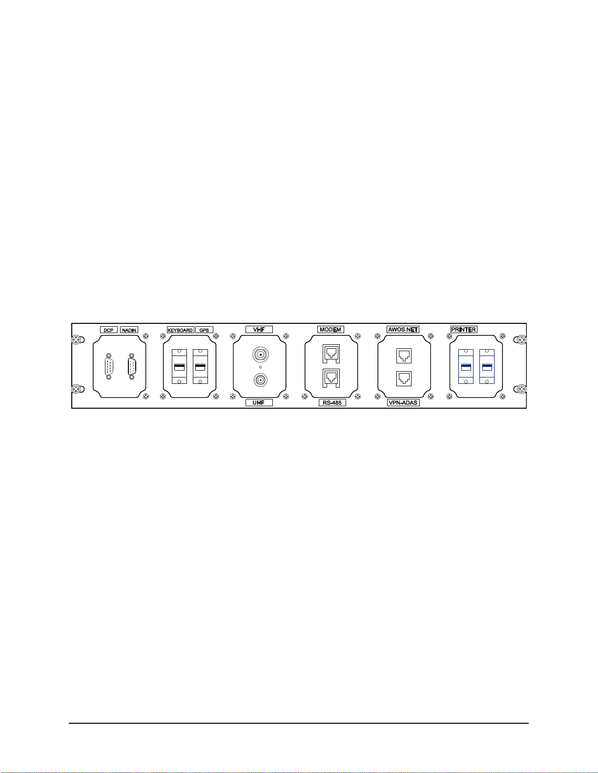
2.3 CDP Top-Shelf Components 5
2.4 CDP Bottom-Shelf Components 12
2.5 GPS NTP Time Standard 13
2.6 NADIN Interface Connection 13
2.7 KVM Extender for Remote Operation 14
2.8 AWOS/ATIS Interface 24
2.9 CDP Checkout 29
2.10 CDP Block Diagram 30
3. DATA COLLECTION PLATFORM...................................32
3.1 DCP Mounting 32
3.2 Sensor Wiring 32
3.3 Auxiliary Sensor Wiring 33
3.4 +5 V Power 33
3.5 -5 V Power 33
3.6 Communication Connections 33
3.7 Other RS-485 Connections 34
3.8 Serial Sensor Wiring 34
3.9 AC Power Wiring 35
3.10 DC, Battery Backup, and Solar Power Wiring 35
3.11 +15 V DC Power Input 35
3.12 Battery Power 35
3.13 Solar Power 36
3.14 DIP Switches 36
3.15 DCP Checkout 37
4. MODEL 7150 DUAL DIGITAL BAROMETER .................38
4.1 Installation 38
4.2 Checkout 39
5. MODEL 2020 MICRO RESPONSE WIND VANE ............41
5.1 Installation 41
5.2 Checkout 43
6. MODEL 2030 ANEMOMETER.........................................46
6.1 Installation 46
6.2 Checkout 48
7. MODEL 2040 ULTRASONIC WIND SENSOR ................49
7.1 Installation Guidelines 49
7.2 Mounting 49
7.3 Wiring 51
7.4 Checkout 53
8. MODEL 5190 TEMPERATURE/RH SENSOR................. 54
8.1 Installation 54
8.2 Checkout 55
9. MODEL 8190 MOTOR ASPIRATED RADIATION SHIELD57
9.1 MARS Installation 57
9.2 Probe Installation 57
9.3 Checkout 58
10. MODEL 6021/6022 TIPPING-BUCKET RAIN GAUGES59
10.1 Siting 59
10.2 Installation 59
10.3 Checkout 61
11. MODEL 6498 PRESENT WEATHER AND VISIBILITY
SENSOR........................................................................ 62
11.1 Sensor Siting 62
11.2 Sensor Installation 63
11.3 Electronics Enclosure Installation 64
11.4 Power Connection 65
11.5 Ground Cable Installation 66
11.6 DCP Signal Connections 67
11.7 Additional Kits 68
11.8 Checkout 70
12. MODEL 8339 CEILOMETER......................................... 77
12.1 Unpacking 77
12.2 Installation 78
12.3 Checkout 84
13. MODEL 6500 THUNDERSTORM/LIGHTNING SENSOR86
13.1 Overview 86
13.2 RFI/EMI Precautions 86
13.3 Sensor Installation 87
13.4 Checkout 90
14. MODEL 6495 FREEZING RAIN SENSOR .................... 91
14.1 Mechanical Installation 91
14.2 Power Connections 92
14.3 Data Connections 92
14.4 Checkout 92

C O N T E N T S AWOS 3000 INSTALLATION AND CHECKOUT
ii
15. FOLDOVER TOWER OPERATIONS.............................93
15.1 Lowering the Tower 93
15.2 Raising the Tower 93
APPENDIX A. DRAWINGS ..................................................94

U S I N G T H I S M A N U A L
1
1. Using This Manual
This manual details installation and checkout procedures for the All Weather, Inc. Automated
Weather Observing System (AWOS) 3000. The AWOS 3000 is available in multiple configura-
tions, with each AWOS configuration having a unique suite of sensors. This manual is organized
around the individual sensors, with each sensor covered in its own chapter. A table at the
beginning of each chapter lists the AWOS configurations that include the sensor.
The first two chapters cover installation and checkout of the Central Data Processor (CDP) and
Data Collection Platform (DCP), which are included in all systems. The remaining chapters
cover the installation of the sensors and their accessories.
Detailed installation drawings and wiring diagrams are provided in Appendix A.
Checkout procedures are provided for each sensor or component. These are intended to verify
operation when a sensor or component is replaced in an existing system. When a complete
system is installed, checkout is accomplished by performing the Annual System Revalidation
procedure described in the AWOS 3000 Maintenance Manual (3000-027).
1.1 General Precautions
Note that ultraviolet-resistant cable ties must be used whenever cable ties are called for.
Note that the metallurgy of the stainless U-bolts will cause the nuts to seize to the U-bolts and
twist them off. Lubricate the threads with anti-seize compound before assembling.
Electrostatic discharge (ESD) precautions must be followed when working with printed circuit
boards and wiring the data interfaces. At a minimum, wear a grounding wrist strap and connect
the ground to a chassis ground inside the enclosure you are working in.
Observe basic electrical safety procedures such as turning the power or circuit breaker off when
working with the AC power interfaces.
All test and calibration equipment must be traceable as specified by the National Institute of
Standards or other standards organizations where specified.
Chapter
1

C E N T R A L D A T A P R O C E S S OR
2
2. Central Data Processor
AWOS
A
AWOS
AV
AWOS
I
AWOS
II
AWOS
III
AWOS
IIIP
AWOS
IIIT
AWOS
IIIPT
AWOS
IIIPTZ
CDP
The Central Data Processor (CDP) is mounted in an industrial-grade rack (Figure 1) along with
an Uninterruptible Power Source (UPS), VHF ground-to-air radio, voice/RMM (Remote Main-
tenance Monitoring)) modem, and any of the CDP options. The available options include UHF
data link radio, AWOS Net, and AWOS/ATIS Interface.
Figure 1. AWOS 3000 CDP Rack
Chapter
2

C E N T R A L D A T A P R O C E S S OR AWOS 3000 INSTALLATION AND CHECKOUT
3
2.1 CDP Installation
The CDP is self-contained. It is installed indoors, at a location with access to AC power and any
auxiliary communication and data lines required. Installation of the CDP primarily involves
routing external cables into the CDP rack and connecting them to the CDP back panel. The
installation of individual CDP options (UHF Radio, etc.) is covered later in this chapter in the
sections devoted to those options.
The CDP is a 22" × 20.5" × 20" 11RU small equipment rack that weighs 138 pounds. The CDP
must be place in a stable location for its size and weight.
Drawing 3000-019 in Appendix A provides the CDP wiring diagram for reference.
2.1.1 Back-Panel Connections
Connections to external devices and data sources (such as the AWOS DCP, ADAS, GPS NTP
server, and printer), as well as internal components (such as VHF Radio and Modem) are made
at the back panel. The back panel is located inside the CDP rack, just above the bottom shelf (see
Figure 9). Figure 2 shows the back panel connectors.
Figure 2. CDP Back Panel Connectors (front end)
External cables are routed to the back panel through an access hole located in the right rear
corner at the top of the rack enclosure.
2.1.2 Connecting Power
Power is supplied to the CDP through the UPS housed in the base of the CDP rack. A power
cord is included and installed, and is routed through the access hole in the top of the CDP
enclosure. Connect this power cord to a suitable AC outlet.
2.1.3 Connecting the VHF Antenna
The VHF antenna and antenna cable must be installed. A mast for the antenna should have been
installed as part of the site preparation. The cable from the VHF Ground-to-Air (GTA) radio
antenna must be routed to the CDP rack and connected to the back panel.
1. Using the radiator length chart on the UHF/VHF Antenna Assembly instructions
(included with the VHF antenna and also in Appendix A), find the optimum radiator
length for the VHF radio frequency.
Note that the radiator lengths remain unchanged from the provided length for standard
VHF GTA frequencies used for AWOS systems.

C E N T R A L D A T A P R O C E S S OR AWOS 3000 INSTALLATION AND CHECKOUT
4
2. Using a hacksaw, trim the radial length of the antenna (Part M489103) to the length
specified. Cover the end of the radiator with the plastic end cap provided with the
antenna.
3. Coat the threaded ends of the radials with PTFE lubricant (supplied with antenna). Attach
the radials to the radiator section.
4. Coat the threaded portion of the U-bolt with PTFE. Attach the U-bolt to the antenna as
shown.
5. Coat the threaded portion of the radiator with PTFE. Attach the completed antenna to the
U-bolt mount as shown.
6. Attach the antenna to the mast installed on the building for the VHF radio antenna.
7. Attach the VHF radio antenna cable (Part M491361) UHF connector to the antenna.
8. Route the antenna cable to the CDP location.
9. Do not trim the antenna cable before you attach the BNC connector to the antenna cable
since shorter antenna cable lengths mean less signal loss, and this translates to an
increased effective radiated power by the antenna, which may then exceed regulatory
specifications. Figure 3 shows how to attach the BNC connector to the antenna cable.
10. Connect the cable to the BNC connector labeled VHF on the front side of the back panel.
Figure 3. BNC Connector Installation

C E N T R A L D A T A P R O C E S S OR AWOS 3000 INSTALLATION AND CHECKOUT
5
2.1.4 Connecting Optional Printer
A USB port is available on the CDP back panel for connection to a printer. Connect the printer
as follows:
1. Connect the USB cable to the printer’s USB port.
2. Feed the USB cable through the access hole in the top of the CDP enclosure.
3. Connect the other end of the printer cable to the USB connector labeled PRINTER on
the front side of the back panel.
2.2 CDP Rack Layout
The CDP components are housed on two shelves inside the rack’s lockable enclosure. The
shelves can be accessed via the front door or either of the side doors. The easiest entry point will
depend on the component being accessed.
2.3 CDP Top-Shelf Components
The top shelf (Figure 5) is attached to the back of the CDP monitor and contains the CPU
assembly, Power Supply, Interface Board, Voice Modem, and communication option (RS-485
converter or UHF radio). The shelf is accessed by removing four screws from the corners of the
front panel (see Figure 4) and sliding the entire shelf, including the monitor, forward.
Figure 4. Front Panel Screws

C E N T R A L D A T A P R O C E S S OR AWOS 3000 INSTALLATION AND CHECKOUT
6
Figure 5. CDP Top-Shelf Components
2.3.1 Communications
The communication options—RS-485 converter or UHF radio—mount to the CDP top shelf in
front of the CPU Board assembly.
2.3.1.1 RS-485 Landline Converter Installation
When an RS-485 landline is used for communicating with the DCP, an RS-485 converter is
installed on the top shelf using Velcro.
The RS-485 converter kit includes:
M417210-00 RJ-11 terminal box
M438205-00 RS-485 converter
M491860-00 serial cable
M491848-00 power cable
M491851-00 RS-485 to panel cable
M491861-00 RJ-11 cable
Velcro

C E N T R A L D A T A P R O C E S S OR AWOS 3000 INSTALLATION AND CHECKOUT
7
The following steps describe how to install the RS-485 converter kit. Figure 6 illustrates the
connections.
1. Power off the CDP.
2. Affix one side of the Velcro backing to the underside of the converter. Attach the other
side of the Velcro backing to the top shelf so that the converter is located at the front-left
of the shelf with sufficient clearance from other components (see Figure 5).
3. Connect the male end of the DB9 connector on cable M491860-00 to the RS-485
converter’s female DB9 connector.
4. Connect the other end of the cable to the DCP connector on the back panel (see Figure 6).
This connection will be modified if the AWOS Net option is installed.
5. Connect the M491848-00 power cable’s yellow wire to the V+ connector on the converter.
6. Connect the power cable’s black wire to the 0V- connector on the converter.
7. Connect the other end of the power cable to the mating connector on the CDP power
supply’s unused power cable.
8. Connect the M491851-00 RS-485 cable to the converter as follows:
Red wire to D+ terminal on the converter.
Green wire to D- terminal on the converter.
Black wire to GND terminal on the converter.
9. Connect the RJ-11 connector end of the RS-485 cable to the back of the RS-485 RJ-11
jack on the back panel (see Figure 2, Figure 6, and Figure 9).
10. If the RS-485 cable from the DCP is alreadyterminated in an RJ-11 jack, which is likely to
be in a wall-mounted terminal box close to the CDP rack, use the M491861-00 RJ-11 cable
to connect to this jack, then feed the cable through the top of the rack and connect the other
end to the front of the RS-485 jack on the CDP back panel. This completes the installation.
If there is no wall-mounted terminal box, use the M417210-00 RJ-11 terminal box in-
cluded with the RS-485 converter kit. Try to install the M417210-00 RJ-11 terminal box
within 3 ft (1 meter) of the CDP rack on a convenient surface using the two mounting
screws that are included. Use the fork lugs provided to terminate the wires from the DCP.
Although the wires from the DCP may have various colors, the corresponding signals
must be matched with the specified colors inside the terminal box.
Connect the RS-485(+) wire to the screw terminal associated with the red wire.
Connect the RS-485(-) wire to the screw terminal associated with the green wire.
Connect the RS-485 ground wire to the screw terminal associated with the black
wire.
Now you may connect the M491861-00 RJ-11 cable as described at the start of this step.

C E N T R A L D A T A P R O C E S S OR AWOS 3000 INSTALLATION AND CHECKOUT
8
Figure 6. RS-485 Landline Converter Installation

C E N T R A L D A T A P R O C E S S OR AWOS 3000 INSTALLATION AND CHECKOUT
9
2.3.1.2 UHF Radio Installation
When a radio data link is used between the DCP and the CDP, a UHF radio is mounted to the
inside of the front panel above the top shelf. The UHF antenna connects to the BNC connector
labeled UHF on the back panel, The radio mounts to the inside of the front panel using Velcro.
The radio kit includes:
Model 20981 UHF Radio
M489171-00 attenuator
M491852-00 antenna cable
M493135-00 serial and power cable
Velcro
The following steps describe how to install the radio kit. Figure 8 illustrates the connections. See
Appendix A for additional information about the antenna and mast assembly and installation.
1. Power off the CDP.
2. Connect the female end of the DB9Install the UHF Data Radio on the inside front panel
using two Velcro pads.
Figure 7. Install Model 20981 UHF Data Radio
3. Add the M489171-00 attenuator to the BNC antenna connector on the UHF Data Radio.
4. Use the M493135-00 cable to connect the DB15 connector on the UHF Data Radio to an
unused connector of the M491862-00 splitter cable from the CDP ATX power.
5. Connect the other end of the cable to the DCP connector on the back panel (see Figure 8).
This connection will be modified if the AWOS Net option is installed.
6. Connect one end of the included antenna cable (M491852-00) to the BNC connector on
the M489171-00 attenuator already connected to the radio.
7. Connect the other end of the antenna cable to the connector on the back side of the back
panel labeled UHF.

C E N T R A L D A T A P R O C E S S OR AWOS 3000 INSTALLATION AND CHECKOUT
10
Figure 8. UHF Radio Installation

C E N T R A L D A T A P R O C E S S OR AWOS 3000 INSTALLATION AND CHECKOUT
11
Connecting the UHF Antenna
When a UHF radio data link is used for communication between the DCP and CDP, the antenna
and antenna cable must be installed. A mast for the antenna should have been installed as part of
the site preparation. The cable from the UHF antenna must be routed to the CDP rack and
connected to the back panel.
1. Install the antenna on the mast provided on the roof of the building, or other appropriate
location. The antenna should be pre-cut for the 450–470 MHz range (standard AWOS
UHF frequency range). Refer to the UHF/VHF Antenna Assembly instructions (in
Appendix A) for more information on how to do this.
2. Connect the UHF connector of the RG-58 antenna cable (Part M491361) to the antenna.
3. Route the antenna cable to the CDP location.
4. Feed the cable through the access hole in the top of the CDP enclosure.
5. If you wish, you may trim the antenna cable before you attach the BNC connector to the
antenna cable. The length of the antenna cable will not affect the operation of the UHF
data link, which will remain within regulatory specifications, although shorter antenna
cable lengths mean less signal loss, and this translates to an increased effective radiated
power by the antenna. The BNC connector is attached as for the VHF antenna cable as
shown in Figure 3.
6. Connect the cable to the BNC connector labeled UHF on the front side of the back panel.

C E N T R A L D A T A P R O C E S S OR AWOS 3000 INSTALLATION AND CHECKOUT
12
2.4 CDP Bottom-Shelf Components
The CDP rack’s bottom shelf (Figure 9) is fixed in place. Components are accessible through the
rack’s front or side doors.
Figure 9. CDP Bottom-Shelf Components
The UPS is housed in the base of the rack, beneath the bottom shelf. The CD drive rests on the
UPS. When not in use, the keyboard is stowed on top of the UPS as well.
The back panel, where cable connections are made to the major components, is mounted to the
back of the rack just above the bottom shelf.
The CDP’s ground cables connect to the ground bar, which is mounted to the rear of the rack
just above the back panel.

C E N T R A L D A T A P R O C E S S OR AWOS 3000 INSTALLATION AND CHECKOUT
13
2.5 GPS NTP Time Standard
A Network Time Protocol server using a GPS receiver (see Figure 10) maintains time synchro-
nization at the CDP. The server, housed in a small, oval package, is installed outside the CDP. It
can often be affixed to the top of the rack, depending on satellite reception.
Figure 10. GPS NTP Time Standard Server
To install the GPS NTP Server:
1. Install the server at a location outside the rack with good satellite reception. Depending
on conditions, the server can often simply be affixed to the top of the rack.
If you experience difficulty accessing the GPS satellite signal, move the server to a
location where it has a clear line of sight to the sky without any metal shielding it.
2. Route the server’s cable through the access hole in the top of the rack enclosure
3. Connect the cable to the USB connector labeled GPS on the CDP’s back panel (see
Figure 2).
2.6 NADIN Interface Connection
If a NADIN interface is used with the AWOS 3000, the NADIN serial cable is routed into the
CDP and connected to the back panel as follows:
1. Route the NADIN cable to the CDP location.
2. Feed the cable through the access hole in the top of the CDP enclosure.
3. Connect the cable to the DB9 connector on the back panel labeled NADIN.
The NADIN connector is a standard male DB9 RS-232 serial connector that accepts the
female DB9 female cable from the optional customer-procured NADIN interface.

C E N T R A L D A T A P R O C E S S OR AWOS 3000 INSTALLATION AND CHECKOUT
14
2.7 KVM Extender for Remote Operation
The KVM Extender Kit (M488342-00) is used to interface a remote operator terminal to the
CDP using a CAT6 Ethernet cable between the local and remote KVM Extender units, with the
Local Unit connected to the CDP. This is necessary when the CDP is installed in an equipment
room and the actual operator of the AWOS is located elsewhere, such as in the control tower.
The remote location will allow the same access to the CDP as if the user is physically at the
CDP. This location must be within 700 ft of the CDP.
Figure 11. KVM Extender
The KVM Extender (M406245-00) consists of the following parts.
1. Local Unit –This unit connects to the CDP. The top unit in Figure 11 is a front view of
the Local Unit.
2. Remote Unit –This unit is located where the operator terminal is desired. The bottom
unit in Figure 11 is a front view of the Remote Unit.
Note that the Local Unit and the Remote Unit are a matched set. If the need arises to
replace either unit, they must be replaced as a set.
3. Two grounding cables —One grounding cable for the Local Unit, one grounding cable
for the Remote Unit. The grounding cables are used to connect the ground posts of the
Local Unit and the Remote Unit to their respective devices, the CDP and the remote
operator terminal.
4. KVM cable assembly –This cable connects the Local Unit to the CDP’s monitor and
audio speaker/microphone jacks. The cable assembly includes the USB connection to the
motherboard.
5. Two power supplies –One power supply will power the Local Unit and the other power
supply will power the Remote Unit.

C E N T R A L D A T A P R O C E S S OR AWOS 3000 INSTALLATION AND CHECKOUT
15
6. Remote Operator Interface —Monitor, keyboard, mouse, speaker, and microphone.
A customer-supplied standard CAT6 Ethernet cable built to standard TIA/EIA-568-B.2-2001
with RJ-45 connectors wired to the T568B scheme is used to connect the Remote Unit to the
Local Unit. Figure 12 shows a wiring diagram for the cable end. This cable may be up to 700 ft
long and must be a straight-through cable, not a crossover cable.
Figure 12. RJ-45 Connectors Wired to T568B Scheme
The Ethernet cable between the two KVM extender units must not be connected to an Ethernet
network or any other connections. There must be no other connections between the two KVM
extender units.
Other manuals for AWOS 3000
2
Table of contents
Other All Weather Inc Weather Station manuals
Popular Weather Station manuals by other brands

La Crosse Technology
La Crosse Technology WS-9611U instruction manual

Bresser
Bresser MeteoTemp Baro HZ colour instruction manual

La Crosse Technology
La Crosse Technology WS-9077TWC-IT instruction manual

Bresser
Bresser 4 cast PC instruction manual

LEXIBOOK
LEXIBOOK SM1102 manual

PRONAMIC
PRONAMIC RAIN-O-MATIC 4-IN-1 operating instructions