CANADA: 83 Commerce Valley Drive East, Markham, Ontario L3T 7T3 | T: 1.800.661.7251 | Fax: 416.752.6717 | www.allanson.com
USA: 99 Adams Blvd., Farmingdale, New York 11735 | T: 1-631-293-3880 | Fax: 1-631-293-3470
INTRODUCTION:
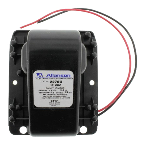
This instruction manual provides you with the application information on the 2260-TP, 2260-TW, 2260-TWG and 2260-P electronic ignitors.
These devices are designed for constant duty and provide the most reliable ignition source for commercial/industrial gas applications.
Before proceeding, identify the model you are installing by the mechanical specifications on reverse side.
ABSOLUTE MINIMUM READINGS:
INSTALLATION:
Install the ignitor assembly on the burner and route the primary leads to the junction box or control panel for connection.
Primary cord sets: Models 2260-TP and 2260-P are shipped with primary plug set. Model 2260-TW has traditional bottom exit pigtaIls and
optional knockouts on case bottom for routing of primary wire to junction box.
Mounting: Model 2260-P is mounted through the case (see above) and via ground tab. Models 2260-TW and 2260-TP are mounted using
the ears/tabs on side of case.
Connect leads as required by wiring method described in control instruction manual or by specific application requirements.
MAINTENANCE:
These ignitors have no moving parts. The only maintenance required is the cleaning of the primary and
TESTING:
WARNING
This procedure is to be carried out by qualified personnel ONLY.
The voltages and currents available can cause serious injury and/or death. Extreme caution is to be used to
avoid contact with the primary live leads. Do not allow any parts of your body to come closer than 5 inches to
the energized secondary terminals or parts of the secondary circuit. Ensure the mid-point of the transformer is
grounded before energizing the primary.
The 2260 Electronic Ignitors can be tested as follows to ensure they are operating properly:
Short Circuit Current Test. Route one connection on a true RMS high frequency milliameter to the output terminal and the second
connection to the ground. Energize the primary with 120 Volts at 50/60 Hz. The reading on the milliameter should be within -15% to +10% of
the rated.
Field Testing. Allanson’s Chek-Mate™ Ignitor / Transformer Tester can be used to test the 6kV Ignitor. You will require a set of 2 alligator
clips. Order Allanson’s Chek-Mate accessory kit part #SC-2200-Kit. Ensure unit is grounded and powered OFF before proceeding. Jump out
oper. controls or thermostat/aquastat. Route 1 alligator clip from shpere of Chek-Mate to secondary wire, and second alligator clip to run
from sphere on Chek-Mate to ground. Power on burner and if the LED light is green (no more than 3 seconds), unit is good.
Input Supply Voltage (VDC):
Input Supply Frequency (Hz):
Primary Volt - Amperes (VA)
Secondary Voltage (kV peak):
Secondary Frequency (kHz):
Secondary Short Circuit Current (mA):
Storage Temperature:
Operating Temperature:
Operating Relative Humidity (%):
Loading Air Gap (inches):
108-132
50/60
72
15.6
-
28
-40 to +80
-30 to +40
90
1/16 to 1/8
ELECTRONIC IGNITORS
INSTRUCTION MANUAL - TYPE 2260-TP, 2260-TW, 2260-TWG & 2260-P
EN
