Allanson AHVPS714-40-MV-PCB Installation instructions

1 Rev. 1 10/06/2020
AHVPS714-40-MV-PCB
14kV/40mA High Voltage Power Supply for Electrostatic Air Cleaner
Specifications and Operating Manual
1. Overview
The 14kVDC/40mA HV power supply is an OEM product and comes without AC
power ON/OFF controls and safety interlocks. It is system integrator
responsibility to assure that all national, state and local electrical safety codes
are followed.
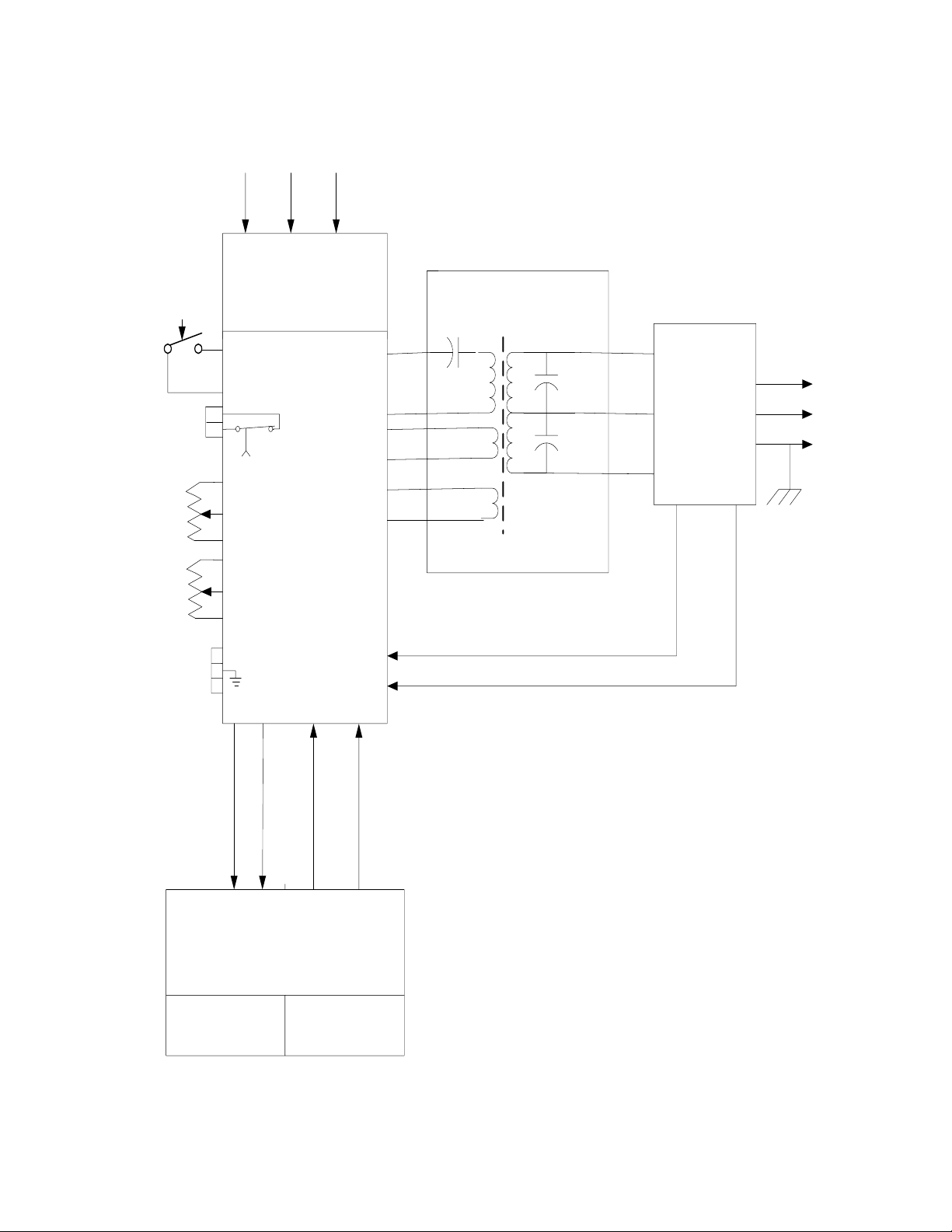
1.1 Principle of operation
The block diagram of HV Power Supply is shown in Fig. 1
The HV Power supply has built in universal input, power factor corrected AC/DC power
converter, which produces 450VDC for the resonant DC/DC HV power converter. The
Resonant Power Converter drives the HV step up transformer, which delivers up to
1.5kV RMS to the HV multiplier. The 4 stage HV multiplier produces up to 14kVDC at
the output (Ionizer) and 7kVDC at the output of second stage (collector).
This PS has capabilities to deliver up to 40mA DC current at 10KVDC or 33mA at
12KVDC (400W) to12 X 24” Linear cells.
The resonant power converter is over voltage, over current, overpower protected
including continuous output short circuit condition.
Operating HV and output current limit are set manually however Intelligent Controller
has the capability to perform the following functions:
1. Monitors internal ambient temperature and turns HV converter off if temperature
is outside operating limits.
2. Monitors HV and output current
3. Maintain the best performance and minimize load cell arcing
4. Reports HV converter status using LED Lamps and optional serial messages on
RS-485 port or Modbus.
Operating HV, Current, Temperature, number of hours of operation, error codes
can be monitored on optional RS-485 output or Modus output terminals.

2 Rev. 1 10/06/2020
Additional HV and current can be monitored on scaled down analog output.
I Monitor –100mV per 1mA
V monitor –100mV per 1KV
5. Keeps track of operating hours
6. Connect to Remote LED diagnostic PCB.
Status LED functionality and simplified flowchart are shown in Appendix A.
2.0 The HVPS has 3 distinct modes of operation:
Voltage Source Mode
Current Source Mode
Burn-in Mode
The HV and Current adjust potentiometers are located on the PCB.
The Burn-in mode is invoked by the pushbutton momentary switch located on PCB or 2 terminals for
remote.
2.1 Voltage source Mode
In Voltage Source Mode the HVPS maintains the preset voltage while current is determined by
the load. As long as current does not exceed the max limit of 40mA the HVPS will maintain the
preset HV.
Voltage mode example settings: The HV was set to 12kV and current limit was set to the
maximum value of 33mA. After connecting the clean load cell, the HVPS was operating at 12kV
with current floating around 33mA. With the same settings and dirty load cell connected, the
HVPS was still operating at 12kV, but the load current dropped to 30mA.
2.2 Current Source Mode
In Current Source Mode the HVPS maintains the preset current while voltage is determined by
the load. If output voltage does not exceed the max limit of 14kV the HVPS will maintain the
preset current.

3 Rev. 1 10/06/2020
Current Mode example settings. The current limit was set to 33mA and HV to 14kV. After
connecting the clean load cell, the HVPS was operating at 33mA current and HV floating around
12kV. With the same settings and dirty load cell connected, the HVPS
was operating with 33mA current, but HV increased to 12.5kV to maintain 33mA current.
2.3 Burns-In Mode.
In normal operation the HVPS is exposed to occasional overload conditions caused by arcing in
the load cells. The HVPS monitors the rate and duration of overload conditions and shut down if
overload condition persists.
New load cells may be contaminated with remnants of machining process and may cause
excessively high rate of arcing for first few hours of operation which may cause the HVPS to
shut down prematurely. To prevent this unnecessary shutdown the Burn In mode was introduced.
When Burn In mode is activated (by pressing the Burn In ON/OFF switch), the HVPS will not
shut down in response to persistent overload condition for 3 hours period.
In Burn-In mode the protection algorithm, which monitors rate and duration of overloads and
shuts down the HVPS if overload persists is suspended for 3 hours.
The Burn In mode can be terminated before 3-hour timer expires by pressing the Burn In
ON/OFF switch.
During Burn In cycle the display alternates between standard Voltage and Current readings
and Burn In cycle message.
4 Rev. 1 10/06/2020
POWER FACTOR
CORRECTOR
RESONANT POWER
CONVERTER
HV MULTIPLIER
CURRENT FEEDBACK
VOLTAGE FEEDBACK
L
NGND
Universal Input
120 - 240 VAC
14kV
7kV
INTELLIGENT
CONTROLLER
VOLTAGE OR
CURRENT TRIM
VOLTAGE MONOTOR
CURRENT MONITOR
STATUS LEDs
POWER TRANSFORMER
MODULE
HIGH
VOLTAGE
ADJUST
HV
GOOD
RELAY
CURRENT
LIMIT
ADJUST
HV_OFF
ISOLATED
RS-485 or Modbus
I MONITOR
V MONITOR
Burn in
On/ off
Fig.1 HV Power Supply Block Diagram

5 Rev. 1 10/06/2020
3.0 Installation and safety
The HV Power Supply must be mounted indoors, protected from weather
Elements, in a location easily accessible by operating service personnel.
The HV Power Supply is equipped with universal input; power factor corrected (PFC)
AC/DC power supply and can operate from 120VAC or 240VAC power lines.
The maximum current draw is 4 Amp from 120 VAC line and 2.0 Amp from 240VAC
line. Use these numbers to select proper wire gage as per applicable standards.
The connection diagram of HV Power Supply is shown in Fig.2 All connections are
made to terminals on the Main Board.
The HV Multiplier has two outputs:
Ionizing Voltage –Labeled as 14kVDC
Collector Voltage –Labeled as 7kVDC
The HV and current adjustment trim pots and status LEDs are located at the edge of
the Main Board as well as AC power input, HV Good Relay and RS-485 serial port.
4.0 Field wiring connections
These instructions are for qualified personnel only. To reduce the risk of electric
shock, do not perform any servicing other than contained in the instructions
unless you are qualified to do so. All wiring must be installed according to
national, state and local codes.
The HV Power Supply requires the following field connections:
1. AC line connection including safety GND (J10, highlighted in green)
2. HV Connection (7kV and 14kV terminal studs, highlighted in red)
3. HV Good Relay contacts (J1, highlighted in green)
4. RS-485 / Modbus communication port (J12, highlighted in green)
5. HV GND and AC GND (corner mounting screws to carrier plate)

6 Rev. 1 10/06/2020
5. Start - up
WARNING!!! HIGH VOLTAGE - RISK OF ELECTRIC SHOCK
Check load cells specifications and number of cells connected before adjusting
the HV and current limits. Instructions below are to operate the HV Power supply
in Voltage Source Mode. Consult factory if Current Source Mode is preferred.
1. Turn the HV Adjust trim pot to the minimum (fully CCW position) and Current
Limit trim pot to the maximum (Fully CW position)
2. Turn AC power on.
WARNING HV comes on as soon as AC power is applied.
Power On LED (Green) and HV On LED (Yellow) should turn On.
Fault LED (red) should stay Off. If Fault LED, comes on follow instruction in
Service/troubleshooting manual.
3. Adjust slowly HV by turning the trim pot clockwise until HV Good LED (Blue)
turns On and output current reaches required value.
Output current adjustment is based on the type and number of load cells connected to
the HV supply. Typical settings are 1mA per cubic foot of load cell.
To facilitate installation and initial adjustment The HV and load current can be monitored
on PC running any ASCII data terminal or Lab View application.
This concludes powering up/adjusting the HV power supply.

7 Rev. 1 10/06/2020
HV TRANSFORMER
HV MULTIPLIER
FAULT
HV
GOOD
POWER ON 7KV
14KV
2
3
1
AC
INPUT
HV GND
HV ADJUST
Min. Max.
Air cleaner 14 kV HV power supply
Connections, indicators and controls
PFC AC/DC
POWER
SUPPLY
RESONANT
POWER
CONVERTER
LINE
NEUTRAL
1
2
3
RS-485
PORT
GND
A B
CURRENT
LIMIT
ADJUST
Min. Max.
2
1
HV
GOOD
RELAY
GND
HV ON
HV
GND
CONNECTION
J 10
INTELLIGENT
CONTROLLER
J 12
J 1
I MONITOR
V MONITOR
Burn in
On/ off Burn in
On/ off
Fig.2 Connections, Indicators and Controls

8 Rev. 1 10/06/2020
6. Specifications
1. Power Input:
a. Voltage: Universal voltage input 120 –240VAC
b. Current: 4A @ 120VAC, 2 Amp at 240VAC
c. Frequency: 50/60HZ
d. Power: < 500W
e. Power Factor : > 0.90
f. Operating efficiency: 82% typical
2. HV Output:
a. Voltage: IONIZER adjustable 7.0 to 14.0 kV DC
COLLECTOR adjustable 3.5 to 7.0kV DC
b. Current: 40mA max at 10kV or 33mA at max 12KVDC
Current limit adjustable 1mA to 40mA
3. Temperature:
Operating: 0 to 50 deg C
Storage: -40 to +80 deg C
4. Overload/Fault protection
a. Automatic shut down when load current exceeds 33mA load at 12KVDC.
Automatic and soft restart when overload condition is removed.
b. Fast control loop (Fast Clamp) keeps the output below 15kV when HV load is
disconnected and when main regulation loop fails.
c. Voltage and Current Faults
d. The recovery from fault condition caused by voltage or current outside the operating
window is monitored and timed by two fault counters - Fault Counter 1 and Fault
Counter 2. Refer to protection flow chart.
e. When voltage or current fault happens, unit restarts automatically after 2 sec delay
and displays error message. The internal Fault Counter 1 is incremented. After 10

9 Rev. 1 10/06/2020
restarts, HV shuts down for 1 min, Fault Counter # 2 is incremented, and Fault
Counter # 1 is cleared.
This process may repeat 3 times (until Fault Counter 2 content exceeds 3) and then
the HV is turned off permanently.
So, the unit allows 5 x 10 = 30 faults with 2 sec recovery time after each fault
and additional 1 min recovery after every 10 faults.
With persisting voltage and/or current type faults it will take ~ 4min before unit shuts
down permanently.
To restart the unit from the permanent shutdown condition input AC power must be
recycled.
Temperature Fault
Recovery process from over temperature condition is not using Fault Timers. When
internal temperature exceeds +60C unit turns HV Off waits until temperature drops below
+60C and restarts. Unit will not start if internal temperature is above +60C
7.0 Intelligent Controller
Microcontroller based, comprising status LED and optional communication port
- Monitors output current, HV and temperature.
- Monitors internal ambient temperature and shuts down the HV when
temperature is outside operating limits
- Counts hours of operation
- Optional Isolated RS-485 or Modbus port outputs Voltage, Current,
Temperature, Hours of operation, Faults alerts.
- Custom protocol using Lab View Application or standard ASCII characters
output to be used with Hyper Terminal or similar serial terminal software.
The simplified flowchart, Status LEDs functionality and serial protocol details are
shown in the Appendix A.
Safety features
- HV ON warning LED
- Dry contacts to signal HV GOOD (contacts closed when HV within operating window)

10 Rev. 1 10/06/2020
8.0 Connectivity
a. Inputs:
120V to 240VAC, Live and Neutral on terminal strip, Earth Ground, #6 Lug on
chassis
b. OUTPUTS:
- Ionizer Voltage, Collector Voltage - # 10 Lugs on # 10 studs.
- High Voltage Return - #6 Lug on chassis
- 250VAC/10Amp dry contacts to indicate HV GOOD condition
- Isolated RS-485 or Modbus port
c. INDICATORS: On Controller PCB and remote PCB
LED Blue Indicator: HV Good (for remote LED terminal)
LED Green Indicator: Input Power On
LED Yellow Indicator: HV ON
LED RED Indicator: FAULTS
The complete functionality of LED indicators and Relay output logic is shown in Appendix A,
Table 1
9.0 Mechanical Specifications
All PCB electrical & components must be mounted in custom metal enclosure with fan
on one side and ventilation levers on other side to create air circulations inside the box.
The PS PCB must be mounted in the enclosure with min of 2” distance from metal surface on all
sides.
Proposed enclosure dimensions 12” W x 15” L x 6” H
Proposed PCB’s will be mounted on Aluminum plate dimensions
11.30” W x 13” L x 0.125” thickness

11 Rev. 1 10/06/2020
10.0 Agency Approvals
rUL, or ETL, optional
11.0 Manufacturer’s Marking:
P/N, Date code, serial #
Appendix A
#
System
Status
BLUE LED -
HV Good,
GREEN LED
- AC Supply
is ON
RED LED
FAULT
YELLOW
LED HV
ON
Relay - Dry
Contact NO
1
System
Good
ON
ON
OFF
ON
ON - dry
contact closed
2
Temp fault
OFF
ON
ON
OFF
OFF - dry
contact open
3
Overload
fault
OFF
ON
2 Flashes &
pause
ON
OFF - dry
contact open
4
Over
voltage
fault
OFF
ON
3 Flashes &
pause
OFF
OFF - dry
contact open
5
System
shutdown
for
10min due
to
OFF
ON
Flashes
continuously
OFF
OFF - dry
contact open
Continues
arcing
below
10KV.
Table1. LED Indicators and Relay output logic

12 Rev. 1 10/06/2020
RS-485 Serial port protocol or Modbus protocol
RS-485 / Modbus is available on J12 terminal block
J12-1 RS-485 NON_INV (A)
J12-2 GND
J12-3 RS-485 INV (B)
Data Format.
Voltage [kVx10] Current [mAx10] Temp [C] Hrs. of operation Fault
142 66 32 300 0
Fault codes:
0No Fault
1Over voltage
2Over current
3Overload (arcing)
4Temperature too high
5HV ON/OFF fault
Table of contents
Other Allanson Power Supply manuals


