ALLCUT HOLE MATIC HoleMatic 31 User manual

THANKS FOR PURCHASING ALLCUT MAGNETIC DRILL MACHINE
Hole Matic
Operating Instructions for
ALLCUT HoleMatic 31/65
General instructions
Machine overview
Safety measures
Before using for the
first time
Preparing
Starting on the machine
Using the machine
Removing blockages
Cleaning
Maintenance
Storage
Technical data
Wiring drawing
Accessories
2
3
4
5
6
7
7
9
9
9
10
10
12
13
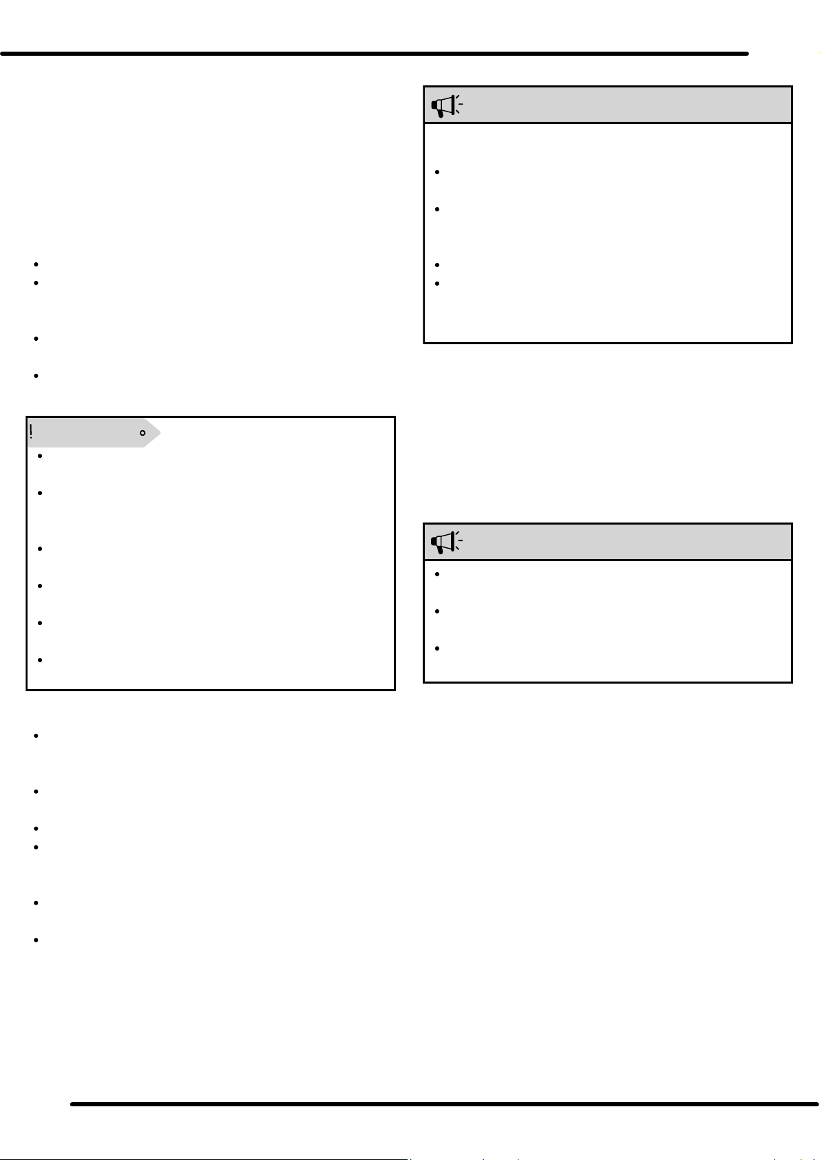
GENERAL INSTRUCTIONS
The ALLCUT HoleMatic 31/65 magnetic drilling machine
is uniquely designed to be used for drilling operations
using twist drills and annular cutters on magnetic
metals and reaming within the limits specified in the
technical data.
Any other use of the machine except stated above is
inappropriate.
INTENDED USE
WARNING
Danger resulting from improper use
If the machine is not used as stated above, and if used
in any other way, the machine may become a source of
danger.
Use the machine as described in the operating
manual.
TABLE OF CONTENT
DEAR CUSTOMER,
Please read the instruction regarding the
startup, safety, cleaning, and other details
mentioned in this operating manual. Ignoring
this may cause serious injury to the operator as
well as the machine.
Keep this instruction manual for future use.
The manufacturer is not responsible for
damage of the machine or accident caused due
to not reading this instruction manual properly,
using the machine other than its purpose, third
party repair, modifying the machine without
our consent or using of unauthorized spare
parts, tools and accessories.
Hole Matic 31/652

SR. NO.
MACHINE PART
1
MAIN BODY
2
PINION
3
HANDLE
4
PANEL
5
ELECTROMAGNET
6
STEEL WEDGES
7
ANNULAR CUTTER (TCT)
8
CUTTER ADAPTER
9
COOLANT BRACKET
10
SPINDLE WITH MT-3 SHANK
11
OPENING FOR EJECTOR PIN
12
GEAR CHANGER
13
DRILL MOTOR
14
STEEL SLIDE
SR. NO.
PANEL
4.1
MOTOR ON/OFF SWITCH
4.2
FUSE HOLDER
4.3
MAGNET ON/OFF SWITCH
1
2
3
4
5
6
9
11
13
14
4.1
4.2
4.3
MACHINE OVERVIEW
7
8
10
12
3Hole Matic 31/65
NOTE
When using electrical tools, please read and follow the
following precautions to prevent any type of injury, fire or
electric shock.
SAFETY MEASURES
BASIC SAFETY MEASURES
Do not use the machine on or near flammable
environment.
Person with heart diseases or medical conditions should
use the machine under supervision or prevent using the
machine.
Person who is unable to operate the machine safely,
should use it under supervision of a responsible person.
Children are not allowed to use the machine.
Before using the machine, check for any visible damages.
Do not operate a damaged machine.
Before beginning the work, check the condition of the
safety chain and the function of the switches on the
machine.
Repairing of the connecting cables should be performed
by a qualified electrician.
Repairs of the machine should be carried out by an
approved specialist workshop or by the manufacturer.
Unapproved repairs can lead to considerable damage to
the operator.
Repairs to the machine during the guarantee period can
only be performed by the manufacturer, otherwise the
guarantee is invalid.
Damaged parts should be replaced by original spare
parts. This ensures the safety of the machine.
Keep an eye on the machine during the operation.
Store the machine in a dry environment.
Make sure the machine is cleaned and free of metal chips
after every operation .
Do not expose the machine to moisture environment.
Do not exceed the capacity of the machine. Refer to the
technical data for the information.
Keep the machine clean, dry and free of oil and grease.
Make sure the machine and main plug is beyond the
reach of water or any other liquid.
Do not operate the machine with panel or motor
housing opened.
If using extension cable, make sure the extended wire is
of 1.5 mm².
Check the condition of the extension wire regularly and
replace it if damaged.
Danger from electric current!
Contact with live wires or components may lead to
serious injury to the operator.
Read the following safety precaution to avoid any electric
shock.
DANGER
Press the red button (O) of the motor switch(4.1) after
every operation.
Switch off the machine with magnet switch (4.3) so the
motor doesn't start.
Risk of accident due to starting of the motor
unintentionally!
Pay attention to the following measures to avoid injuries
due to starting of the motor unintentionally.
Operate the machine with the protective equipment
mentioned below.
Do not wear protective gloves when the machine is on.
The rotating part may catch the glove and torn off the
hand.
Risk of injury due to improper handling of the machine!
Pay attention to these instructions in order to avoid any
type of injury.
ATTENTION
Always carry the machine with the handle.
Before plugging on the machine, check whether the
voltage supply is proper (refer to the technical data
sheet).
Do not pull the main cable to remove the plug from the
main socket.
Potential damage to the machine due to improper use.
Read these instructions to avoid damage to the machine.
WARNING
WARNING
MEANING OF THE SYMBOLS:
1. Wear protective googles.
2. Wear proper hearing protection equipment.
3. Do not put your hand near cutting area
4. Beware of electric shock.
5. Beware of rotating parts machine parts.
1 2 3 4 5
ALWAYS READ THIS MANUAL
BEFORE OPERATING THE MACHINE.
REMEMBER THIS SYMBOLS
4Hole Matic 31/65
SAFETY MEASURES, BEFOR USING FOR THE FIRST TIME
Always switch off the machine when changing tool,
conducting maintenance or cleaning. Wait till the
machine has completely stopped to avoid unintentional
stating of the machine.
Do put your hand into the machine while the machine is
in operation. Remove the metal chips only when the
machine is standstill. Wear the protective gloves when
removing metal chips.
When using a temporary plate for drilling, make sure the
supplied voltage is stable. For more safety, use a safety
belt so the machine holds the plate securely.
Secure the machine with a safety chain when working in
an inclined or vertical position and during overhead
operation. The machine could fall down if the magnet is
loosened or the power drops.
Check that the tool is securely tightened before using.
Do not allow the connecting cable to hang over the
edges.
Do not crush the power cord.
Do not put the main power cord near heated objects or
chemical liquids.
Do not drag the power cord across sharp edges or hot
surfaces.
Put the power cord in such a way that it cannot be
caught by rotating parts of the machine.
The machine stops automatically when the magnet
switch (4.3) is switched off.
Check for any visible signs of damage or missing items on
delivery. Report an incomplete or damaged delivery to your
dealer/supplier/manufacturer.
Preparation
Read the following instructions carefully and take the safety
precautions before starting the machine.
Additional safety measures for
special jobs.
Drilling Vertically
When working on inclined or vertical position or
overhead position, the machine should be secured with
a safety chain to prevent it from falling.
Tighten the safety chain as much as possible around the
handle of the machine.
Check the secure fitting of the safety of the safety chain
before starting the work.
Use proper protection equipment as mentioned on the
machine.
Risk of injury due to machine falling down.
Additional safety measures for
special jobs.
Drilling using temporary plate
Securing the machine with the plate using the safety
chain.
Clamping the plate tightly with the surface that is to be
drilled.
Wear proper safety equipment.
When working of the machine is on scaffolding, the machine
can make sudden vibrations and could slip off the plate,
causing danger. Prevent these by:
NOTE
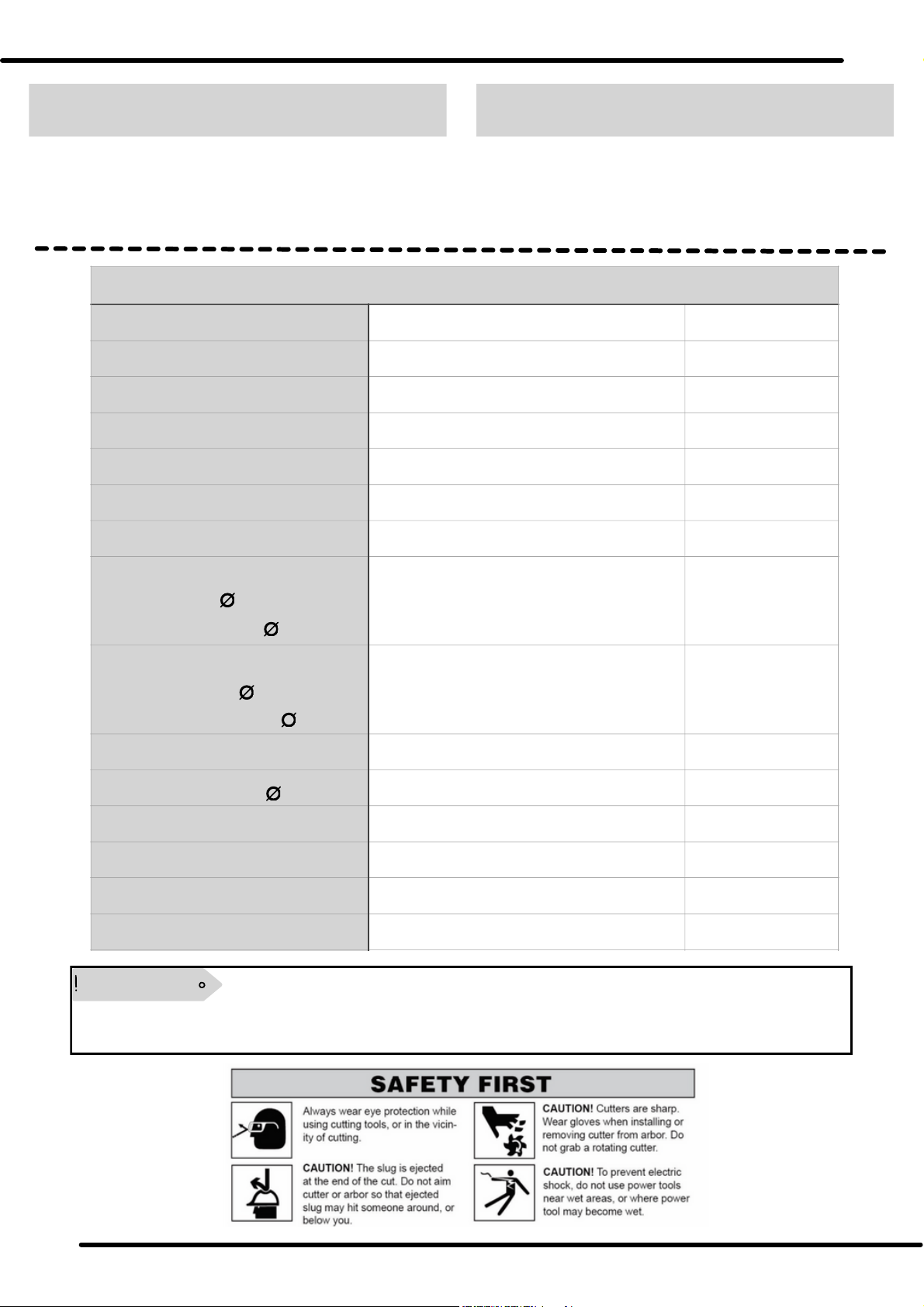
Make sure to make a pilot punch before drilling.
Always use cutting oil or coolant when drilling.
WARNING
WARNING
WARNING
NOTE
ATTENTION
5Hole Matic 31/65

PREPARING
Check the condition of
the surface
The plate should be magnetic.
the electromagnet (5) should be free from grease, oil,
metal chips, or any other dirt.
The plate should be smooth and levelled.
When drilling into low thickness steel plate, we recommend
to use an additional steel plate with 200X200X20 mm
dimensions. Secure the additional plate tightly with the
surface to prevent it from falling.
The magnetic force is dependent on the condition of the
surface/plate to be drilled. If the surface/plate is painted,
coated, uneven or rusted, the magnetic force will be reduced.
To increase the magnetic force of the electromagnet, the
surface/plate should be:
The electromagnet best works with low-carbon steel surface
with a thickness of at least 20mm.
Plate with low thickness
Inserting the tool
Do not use damaged, spoiled or worn out tools.
Change the tools only when the machine is switched off
and at standstill.
After inserting, make sure the tool is engaged tightly.
Only use the tools that are compactible with the
machine.
Risk of injury!
The machine is equipped with MT-3 shank. USE ONLY
TOOLS WITH MT-3 SHANK ON THE MACHINE.
INSERTING THE TOOLS
Before fitting the tool, make sure to clean the shank and
the tool.
Insert the tool into the spindle taper (10) of the machine
from below.
REMOVING THE TOOLS
Turn the tool until the ejector pin slips into the opening
for ejector pin (11).
Loosen the tool by tapping on the ejector pin with a
hammer.
WARNING
INSERTING THE CUTTER
First remove the tool, if any, from the spindle taper (10)
using ejector pin.
Insert the cutter adapter (8) provided into the spindle
taper (10).
Insert the cutter with the pilot pin into the Weldon shank
of the adaptor.
Tighten the grub screws of the Weldon shank.
USING THE MACHINE WITH ANNULAR
CUTTERS.
REMOVING THE CUTTER
Untighten the grub screws using the Allen key and
remove the cutter from below.
Remove the cutter adapter using ejector pin.
Do not use damaged, spoiled or worn out cutters.
Insert or remove the adapter only when the machine is
switched off and at standstill.
Make sure the adapter is engaged tightly.
Make sure that the rod of coolant bracket (9), is
between the steel wedges (6).
Make sure that the grub screws of the Weldon shank is
properly aligned with the flat surface of the cutter.
Assure that the grub screws are tightened properly.
Refer to the figure below.
Risk of injury!
If the cutter is not aligned properly, the cutter will come
out of the shank during the operation, causing injury to
the operator.
Starting on the machine with unaligned cutter will
break the cutter in between the operation.
Risk of injury!
WARNING
ATTENTION
Weldon shank
Grub screws
Flat surface
of the cutter
6Hole Matic 31/65
ATTENTION
STARTING ON THE MACHINE, USING THE MACHINE
Switching the machine ON/OFF
First turn on the magnet switch (4.3).
Then turn ON the machine with the green button (I) on
the drill switch (4.1).
The machine can only be turned on when the
electromagnet is active or turned on.
Selecting the speed range
The machine is equipped with two speed
transmission.
Select the speed according to the material and the
diameter of the hole. Refer to the table below for speed
range.
NOTE
NOTE
ATTENTION
Drilling with the machine
The ALLCUT Hole Matic 31/65 is designed to be used
for drilling with twist drills and annular cutters, and
reaming purposes. Read these instructions to
proceed for your purposes of using of the machine.
Drilling with twist drills
Push the twist drill with MT-3 taper shank into the spindle
taper (10) from below.
Position and fix the machine at the location of the use.
Switch ON the electromagnet by switching ON the
magnet switch (4.3).
Select a suitable gear stage.
Switch ON the drill switch (4.1) by pressing the green
button (I).
Direct the drill to the surface/plate by pulling down the
handle (3).
When drilling with twist drills, proceed as follows:
Under excessive pressure, the drill can wear out and the
machine can be overloaded.
Make sure to remove the metal chips regularly,
especially when with higher drilling depths.
USE PROPER CUTTING OIL OR COOLANT FOR LONGER
TOOL LIFE.
Follow proper drilling direction.
Observe the following instructions when drilling with twist
drill:
NOTE
Changing the gears
First OFF the machine by turning off the drill switch (4.1).
Let the machine is at standstill.
Push in the gear changer (12), and slide up or down the
gear changer.
To change the gears, proceed as follows:
Change the gears only when the machine is turned off
and make sure the spindle taper (10) is not rotating.
Changing gears while spindle is rotating, will crush the
gears of the gear box.
Make sure that the gear changer (12) is slide up or down
till the end and the gears are engaged properly. If not it
will wear out the gears.
If the gears does not engage properly, rotate the spindle
taper (10) a little bit using hand, and slide up or down
the gear changer.
WARNING
GEAR STAGE
SPEED
GEAR 1
260 rpm
GEAR 2
460 rpm
7Hole Matic 31/65
USING THE MACHINE
Drilling with Annular cutter
Reaming with the machine
The ALLCUT HoleMatic 31/65 is a multi-purpose magnetic drill
machine, that can also be used for reaming purpose.
When reaming with the machine, look out for the limits
stated in the technical data.
Reamers with MT-3 taper shank should only be used
with the machine.
Always use proper cutting oil or coolant while reaming
with the machine.
ATTENTION
Insert the appropriate pilot pin into the annular cutter
and insert the cutter into the cutter adapter from below
(8).
Align the cutter and tighten the grub screws of the
Weldon shank.
Put the machine on the surface to be drilled on.
Switch ON (4.3) the magnet switch to enable the
electromagnet. Check that the machine sticks to the plate
properly.
Switch ON the machine by pressing the green button (I)
on the drill switch (4.1).
Slowly feed the handle (3) without exerting much
pressure, directing the cutter to the material to be drilled
on.
When drilling with core drills, proceed as follows:
The cutter adaptor of the ALLCUT HoleMatic 31/65 is
equipped with internal cooling system for the annular
cutter. Always cool down the tool while drilling for
better cutter life.
Turning ON the cooling system
Attach the coolant bottle provided, on the machine.
Connect the tube of the coolant bottle to the brass nipple
on coolant bracket (9) on cutter adapter, by pushing the
tube into the nipple.
Fill up the coolant bottle with coolant or lubricating oil and
screw on the bottle cap.
Turn on the cock on the coolant bottle and let the coolant
pass through the tube.
To turn on the cooling system, proceed as follows:
If the coolant doesn't pass the tube easily, loosen the
bottle cap a little bit. Let the air in the bottle escape.
Assure that the coolant or oil you are using is free of
metal chips or any dirt, to prevent the wearing out of
the tube.
The coolant will come out from the bottom of the cutter
adapter (8), cooling the cutter directly.
The cooling system will only work when you use the
cutter with proper pilot pin.
Use the pilot pin for every operation. It assure proper
rotation of the cutter and enables the cooling system.
The cooling system will not work when drilling in
overhead position.
NOTE
Drilling with annular cutters does not require much
pressure.
Do not apply too much pressure on the cutter. Doing so
will reduce the cutter life, or even break the cutter. And
also the machine will be overloaded.
Always use high performance coolant for better drilling.
Make sure to remove the metal chips regularly, so that
the metal chips do not come in the way of the cutter
while cutting.
Observe the following instructions when drilling with
annular cutter:
ATTENTION
8Hole Matic 31/65

REMOVING BLOCKAGES, CLEANING, MAINTENANCE
Removing blockages
Always use protective gloves when using the machine.
Risk of injury due to broken tool or metal chips.
Switch OFF (4.1) the machine and remove the plug from
the main socket.
Move the machine slide up with the help of the handle
(3).
Remove the metal chips and replace the broken tools.
Switch OFF the drill motor (4.1). Let the electromagnet be
on.
Move the machine slide up with the help of the handle
(3).
Remove the metal chips and check for the tool damage.
Blockages caused by broken tool:
Other blockages:
Always use good quality drill bits and cutters for better
performance.
Do not use damaged or worn out drill bits and cutters.
Do not exert more pressure on the handle (3), if the drill
bit or cutter is worn out or damaged. Doing so will
damage the machine.
Cleaning the machine
Make sure to switch OFF (4.3) completely and remove
the main cord from the main socket.
When using compressed air for cleaning or removing
metal chips, wear the protective goggles and gloves for
safety. Protect other persons in the working area too.
Never use water to clean the electric panel or electric
components.
Prevent the machine from water or other liquids.
Remove the inserted drill bit or tool.
Remove the metal chips and coolant residues.
Clean the tool and the spindle taper (10) on the machine.
Clean the machine slide (14) with clean cloth.
Clean the electromagnet (5) base and let it be free of oil,
metal chips or dirt.
Clean the whole machine and remove all the dirt and
grease.
After each use:
Maintenance
Repairs of electrical components should only be carried
out by the manufacturer or by skilled person.
Danger Caused by unqualified repairs !
Unqualified or third-party repairs leads to serious damage
for the operator and the machine too.
Take the M5 Allen key provided with the tools kit.
Look out for hex bolts on steel wedges (6).
Tighten the hex bolts a little bit and check the slide.
If the slide is too tight loosen the bolts.
Check out for the worn out carbon brushes. Replace the
carbon brushes if needed. Unauthorized carbon brushes will
damage the drill motor (13).
Adjusting the machine slide:
If the machine slide (14) slips down easily, it must be
adjusting. To do this, proceed as follows:
Replacing the carbon brushes
WARNING
WARNING
WARNING
NOTE
ATTENTION
The pilot pin attached to the cutter removes the slug
from the cutter automatically.
But always make sure that the slug is always removed
from the cutter.
DO NOT hammer the cutter if the slug is not ejected.
If the slug is stuck, take a punch and slightly hammer
that punch, to remove the slug without damaging the
cutter (Refer to the figure below).
Always remove the slug from the cutter after every
operation.
WARNING
Slug
Cutter
Pilot pin
Punch
9Hole Matic 31/65
STORAGE, TECHNICAL DATA
Customer service/service
If the machine is too damaged or cannot be repaired by you,
please contact ALLCUT team/dealer/supplier. We will be
happy to provide you with best service.
Storage
If you are not planning to use for a long time, clean the
machine as described in the CLEANING SECTION. Store the
machine and all its accessories in a dry, clean and non-
moisture environment, to prevent it from rusting.
The speed range described in technical data is NO-LOAD speed. the speed may vary at the time drilling
by 20%.
NOTE
Technical data
Drilling capacity:
Tapping capacity
Reaming capacity ( ):
Speed range (NO-Load)
Reverse/forward
Spindle taper
Main cord length
Drilling depth:
Twist drill ( ):
Annular cutter ( ):
Model
Dimensions (L X W X H)
Electromagnet (L X W X H)
Weight
Power supply
Motor W
Noise emission
NO
31
260/460
NO
MT-3
2
ALLCUT 31/65
335 X 190 X 480
235 X 120 X 65
28
220 V single phase
1800
90
m
W
db
mm
mm
kg
mm
rpm
250
50
31
65
Twist drill ( ):
Annular cutter ( ):
mm
mm
mm
mm
10 Hole Matic 31/65
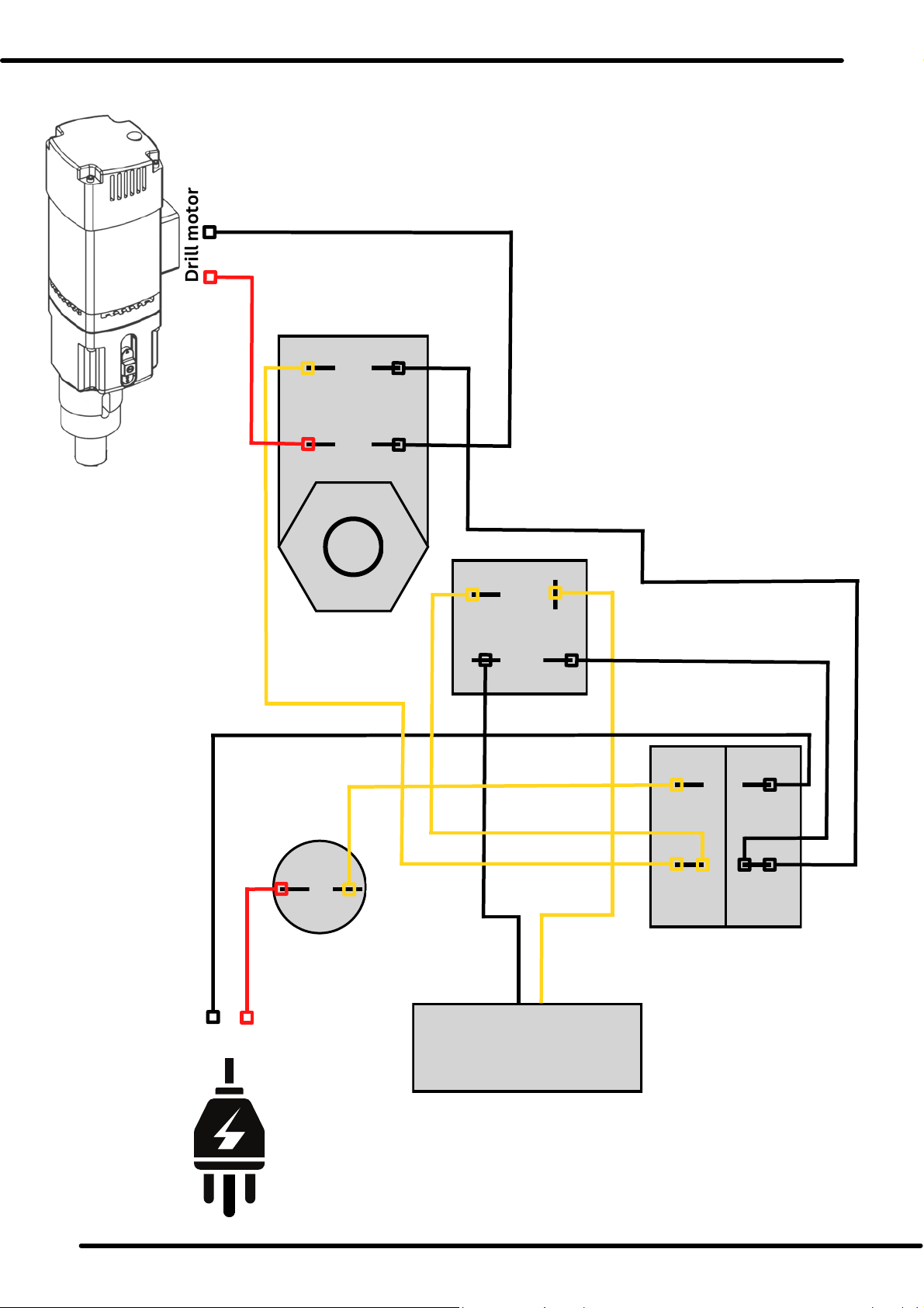
Rectifire
Drill motor
WIRING DRAWING
Electromagnet
Fuse
Holder
Drill Switch
Magnet Switch
Main plug
E1 E2
E2
E1
M1 M2
M1
M2
M3 M4
M4
M3
D1 D2
D3
D4
D1 D2
D4
D3
P1
P1
11Hole Matic 31/65
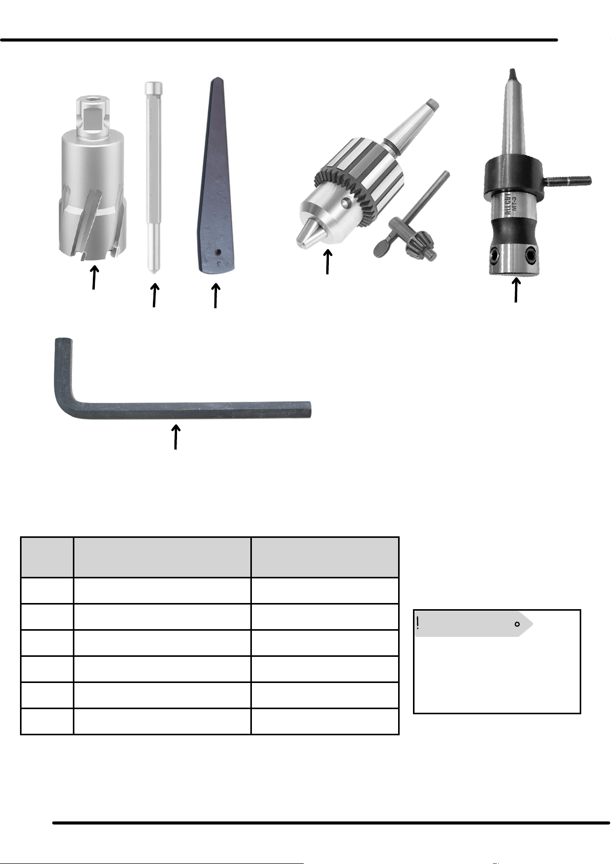
SR. NO.
ACCESSORIES
1
ANNULAR CUTTER (HSS/TCT)
AAC (ALL SIZES)
2
PILOT PIN
AAC
3
EJECTOR PIN
INC
4
DRILL CHUCK ARBOR
AAC
5
CUTTER ADAPTER
INC
8
ALLENN WRENCHES
INC
ACCESSORIES
12
4
5
8
3
(INC= INCLUDED) (AAC= AVAILABLE AS ACCESSORY)
The products which are
marked with AAC are extra
accessory and have to be
paid for each of them.
NOTE
12 Hole Matic 31/65

12Hole Matic 31/65

EXPERIENCE HAPPY AND SAFE DRILLING WITH ALLCUT MAG DRILLS
sales
www.allcut.in
IM_ALLCUT Hole Matic 31/65_A4 2023 ALLCUT MAGNETIC DRILLS
This manual suits for next models
1
Table of contents
Other ALLCUT Drill manuals

Popular Drill manuals by other brands

Makita
Makita HB500 Original instruction

Baier Elektrowerkzeuge
Baier Elektrowerkzeuge BST 200 Translation of the original instruction manual

Makita
Makita HP331D Repair manual

Parkside
Parkside SCHLAGBOHRMASCHINE PSBM 500 A1 Operation and safety notes

B+BTec
B+BTec KARAT 180 Series Translation of the original instructions

Makita
Makita FD02ZW instruction manual


