Alldaq ADQ-22 PXI User manual

Manual
Rev. 1.1 EN
ADQ-22/23 (PXI/PXIe/PCIe)
Digital I/O boards with up to 32 isolated digital inputs, up
to 32 isolated digital outputs, 16 TTL digital I/Os, ADQ-LINK,
optional 8 change-over relays

2
Manual ADQ-22/23-Serie Rev. 1.1
Imprint
Manual ADQ-22/23-Serie
Rev. 1.1
Date: 11.05.2021
Manufacturer and support
ALLNET® and ALLDAQ® are registered trademarks of ALLNET® GmbH Computersysteme. For questions,
problems and product information, please contact the manufacturer directly:
ALLNET®GmbH Computersysteme
Division ALLDAQ
Maistrasse 2
D-82110 Germering
Support
E-Mail: suppor[email protected]
Phone: +49 (0)89 894 222 – 74
Fax: +49 (0)89 894 222 – 33
Internet: www.alldaq.com/support
© Copyright 2015 ALLNET GmbH Computersysteme. All rights reserved.
All information contained in this manual has been compiled with the greatest care and to the best of
our knowledge. Nevertheless, errors cannot be completely ruled out. Specications and contents of this
manual are subject to change without notice.
We are grateful at any time for notication of possible errors.
Trademarks mentioned are registered trademarks of the respective companies.

3
Manual ADQ-22/23-Serie Rev. 1.1
Contents
1. Introduction ��������������������������������������������������������� 5
1.1 Scope of delivery �������������������������������������������������������� 5
1.2 Safety instructions ������������������������������������������������������� 6
1.3 Installation and assembly site ��������������������������������������������� 7
1.4 Brief description��������������������������������������������������������� 7
1.5 System requirements ����������������������������������������������������� 8
1.5.1 Hardware ����������������������������������������������������������� 8
1.5.2 Software ����������������������������������������������������������� 8
2. Commissioning ������������������������������������������������������� 9
2.1 Installation of the card ��������������������������������������������������� 9
2.2 Software installation ���������������������������������������������������� 10
2.2.1 Installation under Windows������������������������������������������� 10
2.3 Test programme �������������������������������������������������������� 10
2.4 ALLDAQ-Manager������������������������������������������������������� 10
3. Function groups ����������������������������������������������������� 13
3.1 Block diagrams ��������������������������������������������������������� 13
3.2 Isolated digital inputs ��������������������������������������������������� 15
3.2.1 Digital input lter��������������������������������������������������� 15
3.2.2 Wiring ������������������������������������������������������������ 15
3.2.3 Programming������������������������������������������������������� 16
3.2.3.1 Easy reading ���������������������������������������������������� 16
3.2.3.2 Streaming operation ��������������������������������������������� 16
3.2.3.3 Interrupt modes ������������������������������������������������� 16
3.2.3.3.1 Bit change �������������������������������������������������� 16
3.2.3.3.2 Bit pattern comparison ��������������������������������������� 17
3.2.3.3.3 Supply voltage missing ��������������������������������������� 18
3.2.3.3.4 Supply voltage too low ��������������������������������������� 18
3.3 Isolated digital outputs �������������������������������������������������� 18
3.3.1 Wiring ������������������������������������������������������������ 18
3.3.2 Programming������������������������������������������������������� 20
3.3.2.1 Easy output ����������������������������������������������������� 20
3.3.2.2 Streaming operation ��������������������������������������������� 20
3.3.2.3 Interrupt modes ������������������������������������������������� 20

4
Manual ADQ-22/23-Serie Rev. 1.1
3.4 Bidirectional digital inputs/outputs ���������������������������������������� 20
3.4.1 Wiring������������������������������������������������������������� 20
3.4.2 Programming������������������������������������������������������� 21
3.4.2.1 Simple input/output ���������������������������������������������� 21
3.4.2.2 Streaming operation ��������������������������������������������� 21
3.5 Relay ���������������������������������������������������������� 21
3.5.1 Wiring ���������������������������������������������������������������� 22
3.5.2Programming ���������������������������������������������������������� 22
4. Anhang �������������������������������������������������������� 23
4.1 Specications ���������������������������������������������������������� 23
4.2 Pin assignments �������������������������������������������������������� 27
4.2.1ADQ-22 ��������������������������������������������������������������� 27
4.2.1.1 78-pin Sub-D socket (ST1) ����������������������������������������� 27
4.2.1.2 25-pin Sub-D socket (ST2) ����������������������������������������� 28
4.2.1.3 25-pin Sub-D socket (ADQ-LINK)������������������������������������ 28
4.2.2 ADQ-23 �������������������������������������������������������� 29
4.2.2.1 78-pin Sub-D socket (ST1) ����������������������������������������� 29
4.2.2.2 25-pin Sub-D socket (ST2) ����������������������������������������� 30
4.2.3 Adapter cable with additional slot plate �������������������������������� 30
4.3 Accessories ������������������������������������������������������������ 32
4.4 Manufacturer and support ����������������������������������������������� 32
4.5 Important notes �������������������������������������������������������� 33
4.5.1 Packaging Ordinance ������������������������������������������������ 33
4.5.2 Recycling notice and RoHS conformity���������������������������������� 33
4.5.3 CE marking �������������������������������������������������������� 33
4.5.4 Warranty ���������������������������������������������������������� 33

Introduction 5
Manual ADQ-22/23-Serie Rev. 1.1 Introduction
1. Introduction
Please check the packaging and contents for damage and completeness before commissioning.
Should any defects occur, please inform us immediately.
• Does anything on the packaging indicate that something was damaged during transport?
• Are there any signs of use on the unit?
You must never operate the appliance if it is damaged. If in doubt, contact our technical cus-
tomer service.
Please read this manual carefully before installing the unit!
1.1 Scope of delivery
• ALLDAQ ADQ-22-PCIe or ADQ-22-PXI/PXIe or ADQ-23-PCIe or ADQ-23-PXI/PXIe
• 78-pin D-sub mating connector
• 25-pole Sub-D mating connector
• Additional slot bracket/panel with 25-pin Sub-D socket on 20-pin socket connector for cPCI
(ADQ-AP-D25F-cPCI) or PCIe systems (ADQ-AP-D25F-PCIe)
• Data carrier with driver software and documentation

6 Introduction
Introduction Manual ADQ-22/23-Serie Rev. 1.1
1.2 Safety instructions
Be sure to observe the following instructions:
• Ensure that the card is very well ventilated in the PC case, as the output drivers can get up
to 100 °C hot under full load.
• It is essential to avoid touching cables and connectors etc. inside the PC with the board.
• Never expose the unit to direct sunlight during operation.
• Never operate the unit near sources of heat.
• Protect the unit from moisture, dust, liquids and vapours.
• Do not use the unit in damp rooms and never in potentially explosive areas.
• Repairs may only be carried out by trained, authorised personnel.
• When commissioning the unit, please observe the installation regulations and all relevant
standards (incl. VDE standards), especially when operating with voltages greater than 42 V.
• We recommend connecting unused inputs to the corresponding reference ground to avoid
crosstalk between the input channels.
• Always disconnect your eld wiring from the power source before making or breaking cable
connections to the board.
• Make sure that no static discharge can take place via the device when handling the card.
Follow the standard ESD protection measures (see also chapter 2.1 on page 9).
• Never connect the units to live parts, especially not to mains voltage.
• Precautions to avoid unforeseeable misuse must be taken by the user.
ALLNET® GmbH Computersysteme accepts no liability for any damage resulting
from improper use.

Introduction 7
Manual ADQ-22/23-Serie Rev. 1.1 Introduction
1.3 Installation and assembly site
The PC plug-in cards of the ADQ-22/23 series are digital I/O cards for industrial use. Depending
on the version, the models of the ADQ-22/23 series are...
... for installation in a free PCI Express slot (ADQ-22-PCIe, ADQ-23-PCIe), or
... for installation in a free PXIe slot (ADQ-22-PXI/PXIe, ADQ-23-PXI/PXIe),
intended. PC plug-in cards must never be operated outside of suitable PC systems. For the
procedure for installing a plug-in card, please read the chapter „Commissioning“ in this manual
and the operating instructions of your PC beforehand.
The ADQ-22/23 series may only be used in dry rooms. PC plug-in cards are not suitable for use
in adverse environmental conditions (e.g. outdoors). Ensure that there is sufcient ventilation.
Ensure that the connection cables are securely seated. Installation must be carried out in such a
way that the cables (PC connection and external wiring) are not under tension, otherwise they
may come loose.
1.4 Brief description
The digital I/O boards of the ALLDAQ ADQ-22/23 series are for use in industrial automation
and control technology. Models for PXIe or standard PCI Express bus are available. The gal-
vanic isolation of 500 VACeff. between eld wiring and PC effectively suppresses interference.
To protect against contact bounce, these cards also offer the option of programming a digital
lter per input port. Streaming operation enables continuous polling of all digital inputs or
output of a bit pattern stream up to approx. 1 kHz.
The ADQ-22 has 32 (2 x 16 bit) isolated digital inputs and the ADQ-23 has 24 (3 x 8 bit) di-
gital inputs. The isolated inputs have a Schmitt trigger characteristic according to IEC 61131-2
(type 1) and are designed for a max. input voltage of 35 V. All isolated inputs are equipped with
status LEDs and can generate an interrupt in case of bit-pattern change, bit-pattern equality as
well as in case of missing external supply.
The ADQ-22 has 32 (2 x 16 bit) isolated digital outputs and the ADQ-23 has 16 (2 x 8
bit) digital outputs. Each output can drive up to 0.6 A. Multiple outputs can be connected in
parallel to increase output current, eliminating the need for an external driver stage for many
applications. An external voltage source in the range 11..35 V with sufcient power must be
provided to supply the outputs. The output drivers are equipped with thermal overload protec-
tion, current limiting, short-circuit protection and undervoltage monitoring.
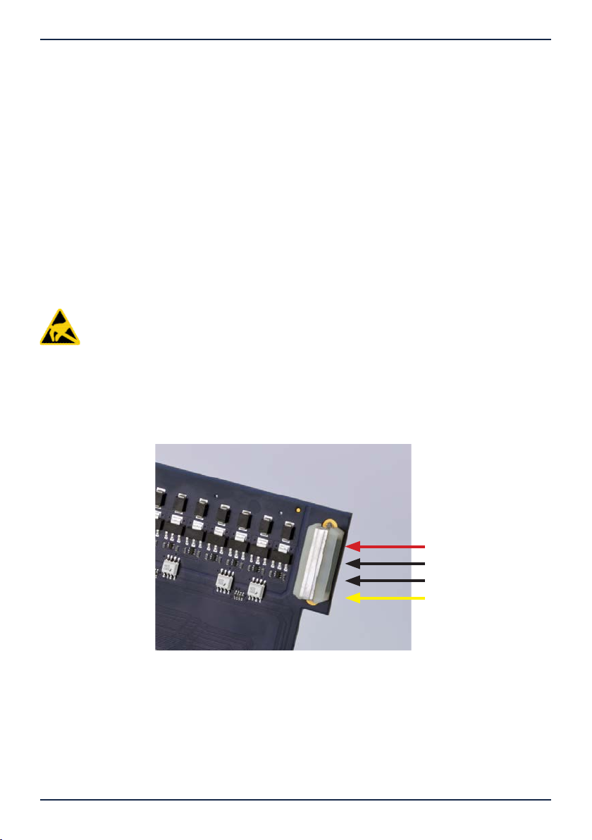
Via an adapter cable with slot bracket, a further 8 TTL digital inputs/outputs can be used,
which are addressed as a bidirectional 8 bit port. These are suitable for connecting accessory
products, for example.
The ADQ-23 also has 8 changeover relays (35 V/1 A)..

8 Introduction
Introduction Manual ADQ-22/23-Serie Rev. 1.1
1.5 System requirements
1.5.1 Hardware
• PC system with a current Intel® or compatible processor based
on the x86(-64) architecture.
• One free PCI Express x1 or CompactPCI Serial slot (4 TE)
1.5.2 Software
Included with the card is a Plug&Play driver for Windows Microsoft and higher (32 and 64 bit)
as well as a function library (API) with code examples for high-level language programming.
Please note the information in the corresponding help le adqSDK.chm.
Details on programming can also be found in the help le adqDriver.chm, which you can call up
via the „ALLDAQ Manager“ in the info area of the taskbar (usually at the bottom right) or the
Windows Start menu.

Commissioning 9
Manual ADQ-22/23-Serie Rev. 1.1 Commissioning
2. Commissioning
2.1 Installation of the card
Before installing the card, please read the manual of your computer regarding the installation
of additional hardware components.
The card should be handled with care to ensure that the unit is not damaged by electrostatic
discharge (ESD), mechanical stress or unauthorised power surges. Precautions should also be
taken to avoid electric shock. Follow standard ESD protection measures.
Note the following procedure:
• Pull out the mains plug of the PC system.
• Open the housing as described in the manual of your PC system.
• Make sure that no static discharge can take place via the card when it is inserted. At least
one hand should be earthed to discharge static charge.
• Only for PCI Express models: for the +5V supply of the card, an additional supply via the PC
power supply unit is required (current consumption without load typ. 300 mA). To do this,
connect a free power supply connector of your PC (as also used for supplying drives) to the
corresponding MOLEX connector on the PCIe card (see the following illustration). If requi-
red, adapters (cables), e.g. from 13-pin SATA power supply plug to 4-pin MOLEX socket, are
available from specialist dealers.
+5 V (PC)
GND_PC
GND_PC
n. c.
Fig. 1: 5 V supply for PCI Express models

10 Commissioning
Commissioning Manual ADQ-22/23-Serie Rev. 1.1
• Insert the plug-in card carefully and with little pressure into the slot provided. Make sure
that the card is not tilted and that it is fully inserted.
• If you want to use the additional slot bracket to use the TTL digital I/Os, select two adjacent
slots for installation. Remove (if necessary) an additional blanking plate for the slot.
• Screw down all slot plates.
• Close the housing again as described in the manual of your PC system.
2.2 Software installation
2.2.1 Installation with Windows
Basically, the following procedure applies:
Start the menu-guided installation of the ALLDAQ driver by executing the ALLDAQDriverSe-
tup64.exe (or ..32.exe) in the target directory of your download.
After successful installation, you will nd the ALLDAQ Manager in the notication area of the
taskbar, which gives you access to the Software Developer Kit (SDK), hardware manuals, help
les and utility programmes.
ALLDAQ measuring cards are recognised by Windows after installation and hardware drivers
are loaded automatically.
2.3 Testing programme
Simple test programmes can be found in the ALLDAQ SDK. There you will nd a subfolder „Ap-
plications“ for the respective programming language with test programmes for your ALLDAQ
hardware.
With the ALLDAQ Manager you can query various information of the installed
ALLDAQ hardware.

Commissioning 11
Manual ADQ-22/23-Serie Rev. 1.1 Commissioning
2.4 ALLDAQ Manager
The ALLDAQ Manager for Windows gives you a quick overview of the parameters of the ADQ
driver system and provides central access to software tools and help les. You will nd the ALL-
DAQ Manager in the info area of the taskbar (usually in the bottom right-hand corner).
ALLDAQ Manager at a glance:
• Information about the installed ALLDAQ hardware at a glance
• XML export of the driver conguration for archiving and support
• Tool for interactive display of the pin assignment with possibility of PDF generation
• Tool for user synchronisation
• Convenient access to the Software Developer Kit (SDK) for high-level language program-
ming with examples and simple test programs
• Quick access to help les (*.chm)
Fig. 2: ALLDAQ Manager and SDK programmes

12 Function groups
Function groups Manual ADQ-22/23-Serie Rev. 1.1

Function groups 13
Manual ADQ-22/23-Serie Rev. 1.1 Function groups
3. Function groups
3.1 Block diagrams
Block diagram ADQ-22
ADQ-22
DO_C15…0
DIO_E/F7…0
GND_EXT
DI_A15…0
GND_EXT
VEXT_DO
GND_PC
VCC_OUT (+5 V)
DO port C
GND_EXT
VEXT_DI
DI_B15…0
IRQ
DO_D15…0
GND_EXT
VEXT_DO
IRQ
DI port A
DI port B
DO port D
DIO port E/F ADQ-LINK
Pin plug 78-pin Sub-D socket
Address/
data bus
CompactPCI (PXI) / PCI-Express-Interface (PXIe)
Molex connection
(+5V for PCI Express)
Interrupt
Control and
interrupt logic
IRQ
Bit pattern comparison
Bit pattern change
16 bit digital input
IRQ
Bit pattern comparison
Bit pattern change
16 bit digital input
Temperature monitoring
TTL-I/Os
(2 x 8 bit port)
Current limit per channel
Opto-isolated up to 500 V
25-pin Sub-D socket
Pin plug
25-pin Sub-D socket
Digital
lter
Digital
lter
16 bit output port
16 bit output port
16 bit input port
16 bit input port
Fig. 3: Block diagram ADQ-22
• 32 isolated digital inputs (2 x 16 bit ports) with programmable lter
• 32 isolated digital outputs (2 x 16 bit ports)
• 16 bidirectional TTL digital I/Os (2 x 8 bit ports) usable via supplied adapter cable
if required
• 1x ADQ-LINK can be used via supplied adapter cable if required

14 Function groups
Function groups Manual ADQ-22/23-Serie Rev. 1.1
Block diagram ADQ-23
ADQ-23
DO_E7…0
DIO_G7…0
GND_EXT
DI_A7…0
GND_EXT
VEXT_DO
GND_PC
VCC_OUT (+5 V)
DI Port C
GND_EXT
VEXT_DI
DI_B7…0
IRQ
DO_F7…0
GND_EXT
VEXT_DO
IRQ
DI Port A
DI Port B
DO Port E
DO Port F
Relay P
ort D
DIO Port G
GND_EXT
DI_C7…0
CO_x
NO_x
NC_x
IDC connector
78-pin D-Sub female connector
Address-/
data bus
CompactPCI Serial / PCI Express interface
Molex connector
(+5V for PCI Express)
Interrupt
Control and
interrupt logic
Temperature monitoring
TTL-I/Os
(1 x 8 bit port)
Current limitation per channel
Isolated up to 500 V
IRQ
Bit-pattern match
Bit-pattern change
8 bit digital input
IRQ
Bit-pattern match
Bit-pattern change
8 bit digital input
IRQ
Bit-pattern match
Bit-pattern change
8 bit digital input
Digital
lter
Digital
lter
Digital
lter
8 bit output port
8 bit output port
8 bit input port
8 bit input port
8 bit input port
Fig. 4: Block diagram ADQ-23
• 24 isolated digital inputs (3 x 8 bit ports) with programmable lter
• 16 isolated digital outputs (2 x 8 bit ports)
• 8 bidirectional TTL digital I/Os (1 x 8 bit port) usable via supplied adapter cable if required
• 8 change-over relays (SPDT)

Function groups 15
Manual ADQ-22/23-Serie Rev. 1.1 Function groups
Block diagram ADQ-23
ADQ-23
DO_E7…0
DIO_G7…0
GND_EXT
DI_A7…0
GND_EXT
VEXT_DO
GND_PC
VCC_OUT (+5 V)
DI Port C
GND_EXT
VEXT_DI
DI_B7…0
IRQ
DO_F7…0
GND_EXT
VEXT_DO
IRQ
DI Port A
DI Port B
DO Port E
DO Port F
Relay Port D
DIO Port G
GND_EXT
DI_C7…0
CO_x
NO_x
NC_x
IDC connector 78-pin D-Sub female connector
Address-/
data bus
CompactPCI Serial / PCI Express interface
Molex connector
(+5V for PCI Express)
Interrupt
Control and
interrupt logic
Temperature monitoring
TTL-I/Os
(1 x 8 bit port)
Current limitation per channel
Isolated up to 500 V
IRQ
Bit-pattern match
Bit-pattern change
8 bit digital input
IRQ
Bit-pattern match
Bit-pattern change
8 bit digital input
IRQ
Bit-pattern match
Bit-pattern change
8 bit digital input
Digital
lter
Digital
lter
Digital
lter
8 bit output port
8 bit output port
8 bit input port
8 bit input port
8 bit input port
Fig. 4: Block diagram ADQ-23
• 24 isolated digital inputs (3 x 8 bit ports) with programmable lter
• 16 isolated digital outputs (2 x 8 bit ports)
• 8 bidirectional TTL digital I/Os (1 x 8 bit port) usable via supplied adapter cable if required
• 8 change-over relays (SPDT)
3.2 Isolated digital inputs
The ADQ-22 has 2 isolated digital input ports with 16 bits each and the ADQ-23 has 3 isolated
digital input ports with 8 bits each. The isolated inputs have a Schmitt trigger characteristic
according to IEC 61131-2 (type 1) and are designed for a max. input voltage of 35 V. All isolated
inputs are equipped with status LEDs. The isolation voltage against PC ground is 500 VACeff
according to EN60664-1 or UL1577.
If required, all inputs can be monitored for bit change or bit pattern equality and evaluated as
an interrupt event. In addition, an interrupt can be triggered if the external voltage supply is too
low (VEXT_DI < 8 V) or missing (VEXT_DI < 12.1 V).
3.2.1 Digital input lter
To prevent unwanted effects caused by contact bounce, you can programme a digital lter for
each input port. Choose between the following values:
10 ms (N = 1248) / 3.2 ms (N = 400) / 1.0 ms (N = 125) / 10 µs (bypass). The scan frequency is
100 kHz (typ.).
0
1
2
N-1
N-2
N-3
Scan frequenc
y
Input DI_x
Fi
lter output
F
ilter state
Signal is 1
Signal is 0
Filter time
Signal is
unchanged
Fig. 5: Digital input lter
3.2.2 Wiring
The isolated inputs have a Schmitt trigger characteristic according to IEC 61131-2 (type 1) and
are designed for the input high level UIH of typ. 24 V which is common in control technology.
Observe the following conditions:
• Threshold voltage L x H: > 15 V @ VEXT_DI = 24 V
• Threshold voltage H x L: < 11 V @ VEXT_DI = 24 V
• Hysteresis: typ. 1 V
The external supply VEXT_DI can be in the range 9.6..35 V, we recommend 24 V. Note that a
ground connection must always be made from the ext. circuitry to the reference ground of the
isolated digital inputs (GND_EXT). The digital input section and the digital output section use
GND_EXT together.

16 Function groups
Function groups Manual ADQ-22/23-Serie Rev. 1.1
Digital
filter
Fig. 6: Wiring of the isolated digital inputs
3.2.3 Programming
All input ports (DI_x) can be programmed independently of each other. The port direction is
predetermined by the hardware.
A digital lter can be programmed for each port: 10 ms / 3.2 ms / 1 ms / 10 µs (bypass).
3.2.3.1 Read single value
In this operating mode, you can read in one digital value at a time in the respective port width.
Follow the procedure described in the online help.
3.2.3.2 Streaming operation
The software-controlled streaming mode enables the continuous reading of the digital inputs
up to 1 kS/s port by port.
Follow the procedure as described in the online help.
3.2.3.3 Interrupt modes
If required, the isolated input ports can be monitored for bit change or bit pattern equality and
evaluated as an interrupt event. In addition, an interrupt can be triggered if the external voltage
supply is missing or too low. Programming is done in the „Interrupt“ operating mode.
3.2.3.3.1 Bit change
In the „bit change“ operating mode, one or more input bits can be masked that are to be moni-
tored for a change of state. One bit mask each for rising and falling edge denes which bit and
which edge should trigger an interrupt. As soon as a corresponding edge arrives at at least one
bit masked with a „1“, an interrupt is triggered (see Fig. 6).

Function groups 17
Manual ADQ-22/23-Serie Rev. 1.1 Function groups
Digital input port
Bitmask
Bitmask
IRQ
b0bx
Fig. 7: Bit change
Example for bit change:
• By passing the value FFHex in the parameter uiPortBitChangeRisingEdge of the
structure SA DQIRQEna ble in function a d q E n a bl eI R Q() for example, all bits of a
port are monitored for rising edge. If only individual bits are to be monitored (e.g. moni-
toring bit b2 for a rising edge), the corresponding bit of the mask must be set to „1“ (e.g.
uiPortBitChangeRisingEdge = 04Hex).
• An interrupt is triggered as soon as a rising edge arrives at bit b2.
• The interrupt event is evaluated with the parameters uiPortBitChangeRisingEdge
or uiPortBitChangeFallingEdge of the structure SADQIRQStatus in function
a d q W a it IR Q(). You receive the information which bit has triggered the interrupt with
which edge (rising/falling)..
3.2.3.3.2 Bit pattern comparison
In the operating mode „bit pattern comparison“, a previously dened reference bit pattern is
compared with the bit pattern present at the corresponding input port. If the bit patterns are
identical, an interrupt is triggered (see Fig. 7).
==
Digital input port
Reference bit pattern
IRQ
b0bx
Fig. 8: Bit pattern comparison

18 Function groups
Function groups Manual ADQ-22/23-Serie Rev. 1.1
Example for bit pattern comparison:
• The reference bit pattern is dened in the uiPortBitPatternValue parameter of the
SADQIRQEnable structure in function a d q E n a b le IR Q().
• Enable the interrupt by passing the boolean value TRUE in the parameter
bPortBitPatternCompare of the structure SADQIRQEnable in function
a d q E n a bl eI R Q().
• As soon as all bits on the input port match the reference bit pattern,
an interrupt is triggered.
• The interrupt event is evaluated with parameter bPortBitPatternCompare of the
structure SA DQIRQStatus in the function a d q W a it IR Q(). TRUE indicates that bit
pattern equality is present.
3.2.3.3.3 Supply voltage missing
If required, an interrupt can be triggered in the absence of an external power supply
(VEXT_DI < 12.1 V).
3.2.3.3.4 Supply voltage too low
If necessary, an interrupt can be triggered if the external voltage supply is too low
(VEXT_DI < 8 V).
3.3 Isolated digital outputs
The ADQ-22 has 2 isolated digital output ports with 16 bits each and the ADQ-23 has 2 iso-
lated digital output ports with 8 bits each. The outputs are equipped with a power FET in
the high path that switches up to 0.6 A per channel. The isolation voltage against PC ground
is 500 VACeff.
3.3.1 Wiring
The outputs are designed for the usual high level of 24 V (UOH = 11..35 V) in control technology.
The max. output current IO is 0.6 A per channel. To increase the output current, several outputs
can be connected in parallel. A ground reference to the external output circuitry must be es-
tablished via GND_EXT. The digital output section and the digital input section use GND_EXT
together.

Function groups 19
Manual ADQ-22/23-Serie Rev. 1.1 Function groups
The output stage offers comprehensive overload protection, including:
• Short-circuit-proof outputs (current limitation per channel)
• Switch-off at current peaks of typ. 1.4 A, e.g. with inductive loads
• Overvoltage protection for VEXT_DO > 47 V
• Undervoltage cut-off: VEXT_DO = min. 7 V/max. 10.5 V, restart at max. 11 V,
hysteresis: typ. 0.5 V
• Thermal overload protection with automatic restart. In case of overload (TTSD = typ.
135°C) the respective channel switches off and switches on again automatically as soon
as the junction temperature has dropped by 10°K. In the event of an overload, the driver
module (per port) can send an interrupt to the PC.
To supply the output stage, an external voltage source that can provide sufcient power must
be connected to the VEXT_DO pins. At full load, this is up to 19.2 A for the ADQ-22 and up to
9.6 A for the ADQ-23. Therefore, connect all Vext and GNDext pins as well.
Attention: the 78-pin sub-D connector (ST1) can heat up!
Fig. 9: Wiring of the isolated digital outputs

20 Function groups
Function groups Manual ADQ-22/23-Serie Rev. 1.1
3.3.2 Programming
The output ports (DO_x) can be programmed independently of each other. The port direction is
predetermined by the hardware.
3.3.2.1 Single-value issue
In this operating mode, you can output one digital value at a time in the respective port width.
Note: An output port can also be read back!
Follow the procedure as described in the online help.
3.3.2.2 Streaming operation
The software-controlled streaming mode enables the continuous output of a bit pattern stream
up to 1 kS/s port by port.
Follow the procedure as described in the online help.
3.3.2.3 Interrupt mode
If the output stage is overloaded, the port concerned is automatically switched off and an
interrupt is generated.
Observe the procedure as described in the online help.
3.4 Bidirectional digital inputs/outputs
The ADQ-22 series has a bidirectional 16 bit digital I/O port (DIO_x). The ADQ-23 series has a
bidirectional 8 bit digital I/O port (DIO_x). If required, the port can be tapped via the 25-pin
sub-D socket ST2. Depending on the form factor used, an additional slot bracket for PCI/PCIe
slots (ADQ-AP-D25F-PCI) or a front panel for cPCI slots (ADQ-AP-D25F-cPCI) is included in the
scope of delivery for this purpose (see pin assignment on page <?> and page 30).
After switching on the supply, all ports are switched to input.
3.4.1 Wiring
When wiring the inputs and outputs, make sure that the TTL level is maintained (see specica-
tions on page 25) and that a reference to PC ground (GND_PC at ST2) must be established. The
max. output current is IO= IOL = IOH = 10 mA.
This manual suits for next models
5
Table of contents
Other Alldaq PCI Card manuals
Popular PCI Card manuals by other brands

D-Link
D-Link DGE-528T Quick installation guide

Centurion
Centurion Guard installation guide

Encore
Encore ENLUSB2-5PCI-BR user manual

ADS Technologies
ADS Technologies PTV-305 Hardware user's guide

ADLINK Technology
ADLINK Technology PCIe-GIE7 Series manual

Airlink101
Airlink101 AWLH3028 Quick installation guide

Adaptec
Adaptec DuoConnect AUA-3121 user guide

StarTech.com
StarTech.com PEXUSB3S44V user manual

Teledyne Lecroy
Teledyne Lecroy PCI Express Gen4 M.2 User manual and quick start guide

ANTAIRA
ANTAIRA msc-401a1 installation guide

Adaptec
Adaptec ANA-6922A Specifications

Rockwell
Rockwell DeviceNet instruction manual