Allegheny GeoVISION User manual

GeoVISION
Deluxe Borehole Video System
User’s Manual
1/15
TM


Allegheny Instruments, Inc. www.AlleghenyInstruments.com
3
Introduction........................................................................................................................................................................................ 4
Quick Setup Guide ............................................................................................................................................................................ 7
System Setup..................................................................................................................................................................................... 15
System Operation.............................................................................................................................................................................17
Maintenance......................................................................................................................................................................................19
Troubleshooting...............................................................................................................................................................................21
Appendix A Deluxe Winch........................................................................................................................................................... 23
Appendix B Standard Stainless Steel Cameras........................................................................................................................... 29
Appendix C Standard Plastic Cameras........................................................................................................................................37
Appendix D Nano Camera ...........................................................................................................................................................45
Appendix E Nano Rotating Mirror .............................................................................................................................................51
Appendix F Dual-Scan Camera.................................................................................................................................................... 55
Appendix G Pan-Tilt Control.......................................................................................................................................................61
Appendix H Fixed Camera Mount ..............................................................................................................................................79
Appendix I Tilting Camera Mount .............................................................................................................................................. 83
Appendix J Standard Centralizer.................................................................................................................................................. 87
Appendix K Cable Support Clamp.............................................................................................................................................. 91
Appendix L Auxiliary Single Light...............................................................................................................................................95
Appendix M Auxiliary Double Light...........................................................................................................................................99
Appendix N Auxiliary Fixed Eight Light..................................................................................................................................103
Appendix O Auxiliary Adjustable Eight Light.........................................................................................................................107
Appendix P Emergency Crank Handle.....................................................................................................................................113
Appendix Q Cable End Replacement Kit ................................................................................................................................119
Limited Warranty ...........................................................................................................................................................................123

Allegheny Instruments, Inc. www.AlleghenyInstruments.com
4
Introduction
Thank you for purchasing an Allegheny Instruments, Inc., GeoVISIONTM Borehole Video System. Allegheny
Instruments is committed to providing the world’s highest quality borehole video systems along with the industry’s
best warranty and technical support. If you have any questions regarding your GeoVISIONTM system, please contact
us. Our office hours are Monday through Friday, 8:00 am to 5:00 pm Eastern Time and our contact information is as
follows:
Support: Sales:
(800) 343-3479 (800) 255-1353
(540) 468-3740 (802) 626-5302
Repair@AlleghenyInstruments.com Sales@AlleghenyInstruments.com
Allegheny Instruments, Inc. Allegheny Instruments, Inc.
1509 Jackson River Road 1509 Jackson River Road
Monterey, VA 24465 Monterey, VA 24465 USA
Terminology
This manual uses the following conventions to highlight
the presence of hazards, potential risk and important
information concerning the operation and maintenance
of this system.
DANGER: Denotes an imminently hazardous
situation which, if not avoided, can result in death or
serious injury.
WARNING: Denotes the presence of a condition
that can cause significant personal injury and/or
property damage and may void the product warranty if
ignored.
CAUTION: Denotes the presence of a condition
that can cause personal injury and/or property damage.
Note:Indicates supplemental information worthy of
attention.
Be sure to follow all instructions and related precautions.
They are intended for your safety and protection.
Foreword
This manual is to be used as a guideline for operation
and maintenance of a GeoVISIONTM Deluxe Borehole
Video System. It is divided into six sections for easy
reference.
Section 1 –Quick Setup Guide
Section 2 –System Setup
Section 3 –System Operation
Section 4 –Maintenance
Section 5 –Troubleshooting
Section 6 –Appendices

Allegheny Instruments, Inc. www.AlleghenyInstruments.com
5
Important Precautionary Information
The information contained on this page appears throughout this manual. Be sure to read and
understand these precautions prior to using the system.
DANGER
This system is not designed for use in
explosive atmospheres.
WARNING
The GeoVISIONTM Deluxe Winch and Control
Panel are not waterproof; both parts should
be protected from water and moisture.
Exposure to excessive moisture can cause a
safety hazard and/or system failure. If these
components are exposed to water, power to
the system should be removed, the power
supply panel should be removed from the
winch, and the components should be dried
immediately.
Failure to clean and dry system components
before placing them in the carrying case can
cause premature failure and void the
warranty.
If the interior of the carrying case is damp or
wet, it should be allowed to dry thoroughly
before the case is closed.
WARNING
This system must be powered from an AC
sine wave power source such as a generator,
commercial power, or a pure sine wave
inverter.
WARNING
Never support a camera by the 3-pin
connector. Always use the camera’s built in
clamp, if it has one, or use a Cable Support
Clamp.
CAUTION
Before using the system, be sure that the
“Camera Select” switch is in the correct
position for the camera you are using. Refer
to figure #6A.
CAUTION
This system is designed for use in potable
water wells. It should not be used in
environments where the plastic components
will come in contact with solvents, oils, or
fuels. Solvents, oils, or fuels can damage
plastic components and be absorbed into the
plastic, allowing contaminants to be
transferred from one well to another.
CAUTION
Chemical damage is not covered by the
warranty.
CAUTION
If the system is used in salt water, all
submerged electrical connections must be
protected using silicon grease. Coat both the
pins on the male connector(s) and the
contacts on the mating connector(s) with
grease. The connectors must be cleaned with
fresh water and dried after each such use.
Damage from use in salt water is not covered
by the warranty.
CAUTION
Plastic cameras should not be subjected to
thermal shock. If a plastic camera is very
cold, it should be allowed to warm to the
borehole temperature in air before it is placed
in the bore. If a plastic camera is hot, it is
best to turn the camera off for about 5
minutes inside the borehole, before it is
submerged. Damage resulting from thermal
shock is not covered by the warranty.
CAUTION
The operating temperature range for plastic
cameras is 32° F (0C) to 100° F (37C). Use
of plastic cameras in temperatures outside
this range can damage the camera and is not
covered by the warranty.
CAUTION
Plastic cameras will warp and leak if operated
or stored at temperatures above 120° F (49°
C). Temperature warped cameras are not
covered by the warranty.

Allegheny Instruments, Inc. www.AlleghenyInstruments.com
6

Allegheny Instruments, Inc. www.AlleghenyInstruments.com
7
Quick Setup Guide
Camera Configuration
The following image illustrates some common ways to configure various cameras based on the type of camera, bore
diameter and intended use. For a detailed description on how to configure each camera, see the appendix for the
camera.
Typical Camera Configurations

Allegheny Instruments, Inc. www.AlleghenyInstruments.com
8
Winch Setup
Set the switches on the top of the Control Panel.
Set the switches on the side of the Control Panel.
Set the Video Source switch
to “FROM CAMERA.”
Turn the Volume knob all
the way down.
Set the Camera switch for
the camera you are using.
Turn off the System
Power switch.
Set the Input Voltage switch
for the proper source
voltage, 115V or 230V.
Turn on all three light switches.
Set the Exposure Control switch to “Normal.”
Turn off the Winch Motor switch.
Rotate the Winch Control knob straight up to
the “Stop” position.

Allegheny Instruments, Inc. www.AlleghenyInstruments.com
9
Insert the winch legs.
Clamp the Depth Encoder to the well casing or a tripod placed over the bore.
Allegheny Instruments, Inc. www.AlleghenyInstruments.com
10
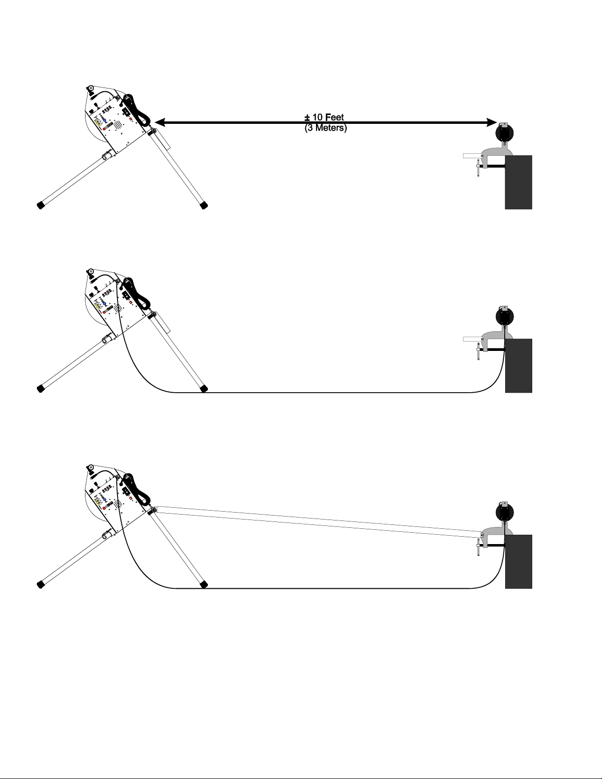
Place the winch on level ground approximately 10 feet (3 meters) from the Depth Encoder.
Connect the Encoder Cable between the winch and the Depth Encoder.
If the borehole is deeper than 600 feet (200 meters), we recommend placing a spacer pipe between the winch and the
Depth Encoder.
Plug in the winch and turn on the System Power switch.
With the Winch Control knob in the “Stop” position, turn on the Winch Motor switch.
Turn the Winch Control knob counterclockwise toward “Down” and spool off enough cable to reach
approximately 3 feet (1 meter) beyond the Depth Encoder.
Turn off the Winch Motor switch and, if necessary, return the Winch Control knob to the “Stop” position.

Allegheny Instruments, Inc. www.AlleghenyInstruments.com
11
Set the Camera switch for the camera you are using and attach the camera to the winch cable.
Mount the monitor on the winch.

Allegheny Instruments, Inc. www.AlleghenyInstruments.com
12
If glare makes viewing the monitor difficult, attach the Sunshade to the top of the monitor. A microphone can also
be attached to the hole in the Sunshade.
Lower the camera into the bore, place the winch cable over the Depth Encoder pulley, and secure it in place with the
pin.

Allegheny Instruments, Inc. www.AlleghenyInstruments.com
13
If desired, connect a video recorder.
If desired, connect a true sine wave inverter to a battery or a vehicle and plug the winch into the inverter.

Allegheny Instruments, Inc. www.AlleghenyInstruments.com
14

Allegheny Instruments, Inc. www.AlleghenyInstruments.com
15
System Setup
Install the Tripod Legs
This step is easier if the winch is placed on an elevated
surface with the rear leg sockets hanging over the
edge. The carrying case makes an acceptable work
surface for this purpose.
Insert the two rear tripod legs into their mating
sockets. The rear legs are the two identical ones and
do not have a brace pole bracket attached to them.
Insert the quick release pins to lock the legs in place.
Lift the winch by its handle and rock it back so that
the two rear legs are on the ground and supporting
the weight of the winch.
Insert the front tripod leg with the brace pole
attachment bar facing away from the winch spool and
insert the quick release pin.
Lower the winch so that it is supported by all three
legs.
Locate the Winch
Place the winch approximately 10 feet from the
borehole keeping it as level as possible.
Remove enough cable from the winch to allow the
end of the cable to extend 3 feet beyond the borehole.
Check the Winch Switches
Check that the Voltage Select switch is set to the
voltage you will be using, 115 or 230 volts AC.
Check that the System Power switch is turned off.
Check that the Winch Motor switch is turned off.
Check that the Winch Control knob is set to “0” or
“Stop.”.
Check that the Camera switch is set to the camera you
will be using.
Check that the Video Source switch is set to “FROM
CAMERA.”
Check that all three light switches are turned on.
Check that the Exposure Control switch is set to
“Normal.”
Install a Brace Pole
If you are logging deeper than 600 feet, it is
recommended that you install a brace pole between
the winch and the Depth Encoder using the
aluminum brackets attached to each.
Install the Depth Encoder
Attach the Depth Encoder to either the well head or
to a tripod positioned over the well.
Connect the grey telephone cord between the winch
and the Depth Encoder. Note that the ends of the
cord are different; the wide connector plugs into the
Depth Encoder, and the narrow connector plugs into
the winch.
Attach the Monitor
If you purchased a monitor with your system, follow
these steps to mount it to the winch.
Thread the bolt on the monitor mount into the hole
on the bottom of the monitor, just enough to engage
the threads.
Position the monitor so it faces the operator, and
tighten the bolt to lock the monitor in position.
Plug the monitor into the mating cord on the Control
Panel.
If glare makes it difficult to see the monitor, attach
the Sunshade to the monitor using the Velcro™ strips
along the top of both the monitor and the Sunshade.
Connect a Microphone
If your microphone requires a battery, be sure that the
battery is installed correctly.
If you purchased a monitor with your system, you can
use a small microphone clip to attach the microphone
to the hole in the Sunshade, so that the microphone is
mounted to the outside of the Sunshade facing the
operator.
Plug the microphone into the jack labeled
“MICROPHONE”on the Control Panel.
Set Up the Camera
Each camera can be configured in a number of ways,
depending on the size of the bore. Refer to the
Appendix that covers the camera you are using for
complete setup instructions. Appendices for the
cameras are as follows:
Appendix B –Standard Stainless Steel Cameras
Appendix C –Standard Plastic Cameras
Appendix D –Nano Camera
Appendix E –Dual-Scan Camera

Allegheny Instruments, Inc. www.AlleghenyInstruments.com
16
Place the Camera in the Bore
Remove the retaining pin from the top of the Depth
Encoder.
Place the camera in the bore and lay the winch cable
over the Depth Encoder pulley. Make sure there is
no twist in the cable between the winch and the
Depth Encoder.
Replace the retaining pin in the Depth Encoder.

Allegheny Instruments, Inc. www.AlleghenyInstruments.com
17
System Operation
Initial Settings
Check that the Voltage Select switch is set to the
voltage you will be using, 115 or 230 volts AC.
Check that the System Power switch is turned off.
Check that the Winch Motor switch is turned off.
Check that the Winch Control knob is set to “0” or
“Stop.”
Check that the Camera Select switch is properly set
for the camera attached to the cable.
Check that the
Video Source switch is set to “FROM CAMERA.”
Turn on all three light switches.
Set the Exposure Control switch to “Normal.”
Turn on the System Power switch.
Testing and On-Screen Depth Display
(OSD) Initialization
Press the “Screen Position” button repeatedly until
you see the OSD numbers on the screen and in the
position you desire.
Rotate the Winch Control knob so that it points
straight up in the “0” position.
Turn on the Winch Motor switch.
Slowly turn the Winch Control knob
counterclockwise to lower the camera into the bore.
Turn the knob back to “0” or turn off the Winch
Motor switch to stop the winch.
When the camera reaches the depth that will serve as
the reference depth, press and hold the two red
buttons to zero the OSD count.
Now is a good time to test the winch controls. If you
are using a Dual-Scan Camera or a Pan-Tilt Control,
test that the joystick is controlling the camera properly
and that the exposure control is functioning correctly.
Check that the light(s) is(are) working properly as
well.
If you plan to record the session, now is the time to
make a short recording (including audio if desired)
and to play it back to be sure everything is working
correctly. For more information on connecting a
video recorder, see Appendix A.
Logging the Bore
Use the Winch Control knob to lower the camera
down the bore. If the camera is going to be
submerged, keep in mind that the first trip down will
see the least amount of sediment. It is often best to
record video on this pass.
In an emergency, the Winch Motor switch or the
System Power switch can be used to stop the winch;
however, using the Winch Control knob rather than
the switches reduces wear and tear on the motor.
Turning off the System Power switch does not reset
the OSD count; however, if the cable is spooled out
or in while the power is off, the change will not be
reflected in the OSD count when power is restored.
When lowering into a bore for the first time, it is
always a good idea to look straight down the bore. If
you are using a Dual-Scan Camera or Pan-Tilt Control
and would like to look sideways, it is a good idea to
stop the winch before doing so.
Retrieving the Camera
When raising the camera out of the bore, it is very
important to dry the cable and wind it neatly on the
winch. Paper towels are an effective way to dry the
cable. Hold the cable in the fold of several paper
towels as you guide the cable neatly onto the winch.
After use, the paper towels can be discarded to reduce
the risk of cross contamination of wells.
WARNING
The GeoVISION Deluxe Winch and Control
Panel are not waterproof and should be
protected from water and moisture. Exposure
to excessive moisture can cause a safety
hazard and/or system failure. If these
components are exposed to water, power to
the system should be removed immediately,
the Control Panel should be removed from the
winch, and the components should be dried
thoroughly.
Failure to clean and dry system components
before placing them in the carrying case can
cause premature failure and void the
warranty.
If the interior of the carrying case becomes
damp or wet, all items should be removed
from the case, and it should be allowed to dry
thoroughly before it is used again.

Allegheny Instruments, Inc. www.AlleghenyInstruments.com
18

Allegheny Instruments, Inc. www.AlleghenyInstruments.com
19
Maintenance
Camera
After each use, flush the 3-pin connector on the rear
of the camera with clean, fresh water. When the
connector is dry, lightly coat the pins with silicone
grease and cover the connector with one of the yellow
nylon caps to protect it from dirt.
Occasionally check for a buildup of silicone grease
inside the 3-pin connector. If a buildup occurs, gently
remove it before cleaning.
Winch Cable
Always use one hand and a clean rag or paper towels
to guide the cable back onto the winch when
retrieving the camera. Wind the cable in neat rows to
ensure that all of the cable fits back on the winch; this
also helps you locate damaged sections in the cable.
Wiping the cable clean and dry extends the life of the
cable and helps prevent cross contamination between
wells.
Control Panel
The Control Panel should be kept clean and dry. If
the foam in the case becomes damp, remove it from
the case and allow it to dry thoroughly before
repacking the case.

Allegheny Instruments, Inc. www.AlleghenyInstruments.com
20
Table of contents


