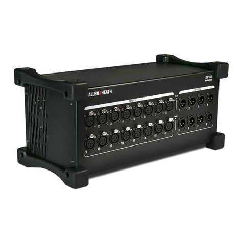
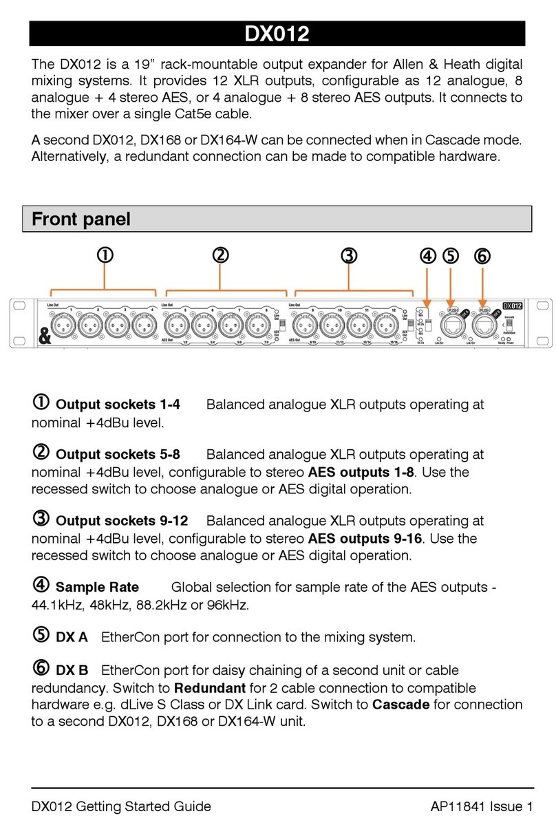
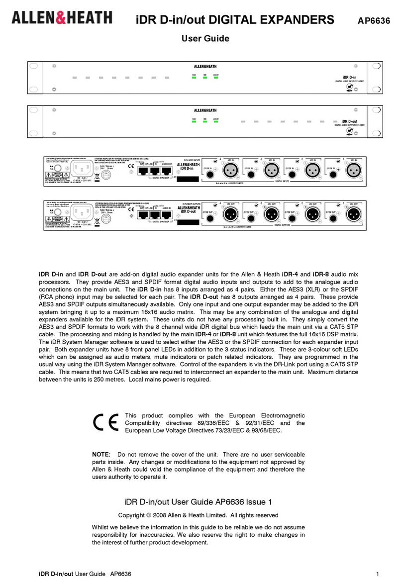
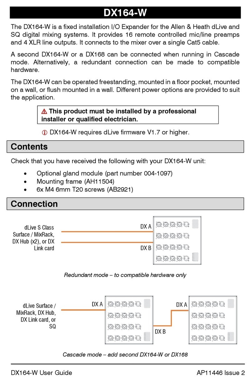
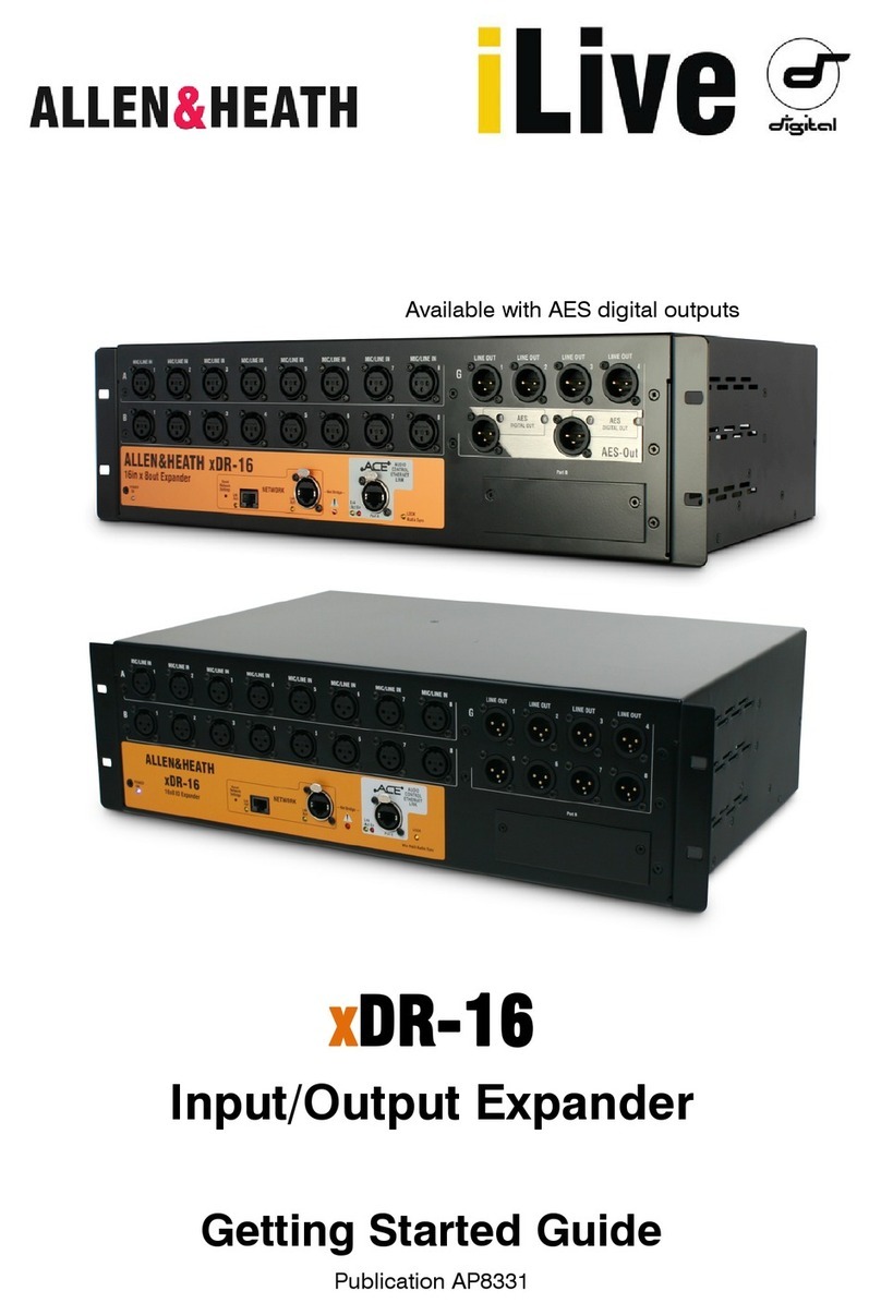
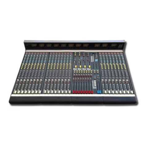
ALLEN & HEATH dLive DX32 User manual

DX32 Getting Started Guide
2
AP10242 Issue 5
DX32 Getting Started Guide
Copyright © 2021 Allen & Heath. All rights reserved.
Allen & Heath Limited, Kernick Industrial Estate, Penryn, Cornwall, TR10 9LU, UK
http://www.allen-heath.com
Limited One Year Manufacturer’s Warranty
Allen & Heath warrants the Allen &Heath -branded hardware product and accessories contained in the
original packaging ("Allen & Heath Product”) against defects in materials and workmanship when used
in accordance with Allen & Heath's user manuals, technical specifications and other Allen & Heath
product published guidelines for a period of ONE (1) YEAR from the date of original purchase by the
end-user purchaser ("Warranty Period").
This warranty does not apply to any non-Allen & Heath branded hardware products or any software,
even if packaged or sold with Allen & Heath hardware.
Please refer to the licensing agreement accompanying the software for details of your rights with respect
to the use of software/firmware (“EULA”).
Details of the EULA, warranty policy and other useful information can be found on the Allen & Heath
website: www.allen-heath.com/legal.
Repair or replacement under the terms of the warranty does not provide right to extension or renewal of
the warranty period. Repair or direct replacement of the product under the terms of this warranty may be
fulfilled with functionally equivalent service exchange units.
This warranty is not transferable. This warranty will be the purchaser’s sole and exclusive remedy and
neither Allen & Heath nor its approved service centres shall be liable for any incidental or consequential
damages or breach of any express or implied warranty of this product.
Conditions Of Warranty
The equipment has not been subject to misuse either intended or accidental, neglect, or alteration other
than as described in the User Guide or Service Manual, or approved by Allen & Heath. The warranty
does not cover fader wear and tear.
Any necessary adjustment, alteration or repair has been carried out by an authorised Allen & Heath
distributor or agent.
The defective unit is to be returned carriage prepaid to the place of purchase, an authorised Allen &
Heath distributor or agent with proof of purchase. Please discuss this with the distributor or the agent
before shipping. Units returned should be packed in the original carton to avoid transit damage.
DISCLAIMER: Allen & Heath shall not be liable for the loss of any saved/stored data in products that are
either repaired or replaced.
Check with your Allen & Heath distributor or agent for any additional warranty information which may
apply. If further assistance is required please contact Allen & Heath Ltd.
ALLEN&HEATH

DX32 Getting Started Guide
3
AP10242 Issue 5
IMPORTANT - Read before starting
Safety instructions
Before starting, read the Important Safety Instructions printed on the sheet supplied with the equipment.
For your own safety and that of the operator, technical crew and performers, follow all instructions and heed
all warnings printed on the sheet and on the equipment panels.
System operating firmware
The function of the DX expander is determined by the firmware (operating software) that the mising system
runs. Firmware is updated regularly as new features are added and improvements made.
Check www.allen-heath.com for the latest version of mixer firmware. Update to the
latest version before connecting the DX Expander. The unit might operate incorrectly
or fail to connect when running earlier firmware.
Software licence agreement
By using this Allen & Heath product and the software within it you agree to be bound by the terms of the
relevant End User Licence Agreement (EULA), a copy of which can be found at www.allen-
heath.com/legal. You agree to be bound by the terms of the EULA by installing, copying, or using the
software.
Further information
Please refer to the Allen & Heath website for further information, knowledgebase and technical support.
For more information on system setup and mixing functions please refer to the product guides available for
download at www.allen-heath.com.
Check for the latest version of this Getting Started Guide.
General precautions
•Protect the equipment from damage through liquid or dust contamination. Cover the expander
when it is not being used for a long period.
•If the equipment has been stored in sub-zero temperatures allow time for it to reach normal
operating temperature before use at the venue. Recommended operating temperature is 0 to 35
degrees Celsius.
•Avoid using the equipment in extreme heat and direct sunlight. Make sure the ventilation slots are
not obstructed and that there is adequate air movement around the equipment.
•Clean the equipment with a soft brush and dry lint-free cloth. Do not use chemicals, abrasives or
solvents.
•It is recommended that servicing is carried out only by an authorised Allen & Heath agent. Contact
details for your local distributor can be found on the Allen & Heath website. Allen & Heath do not
accept liability for damage caused by maintenance, repair or modification by unauthorised
personnel.
Register your product
Register your product online at www.allen-heath.com/register.

DX32 Getting Started Guide
4
AP10242 Issue 5
Packed items
Check you have received the following:
•DX32 expander
•Getting Started Guide AP10242
•Safety Sheet
•IEC mains lead
Introduction
The DX32 is a rack I/O Expander for Allen & Heath 96kHz digital mixing systems. It provides 4 slots for 8ch
analogue or digital I/O cards, in any combination, and a modular power supply with optional redundancy.
It connects to the mixing system over a single Cat cable, or two cables (to compatible hardware) for
redundancy.
Contents
IMPORTANT - Read before starting ............................................................................................................3
Safety instructions .................................................................................................................................3
System operating firmware....................................................................................................................3
Software licence agreement ..................................................................................................................3
Further information ................................................................................................................................3
General precautions ..............................................................................................................................3
Register your product ............................................................................................................................3
Packed items ................................................................................................................................................4
Introduction...................................................................................................................................................4
Contents .......................................................................................................................................................4
1. Installing the Expander ....................................................................................................................5
1.1 Free standing ..........................................................................................................................5
1.2 Rack mounting and flight casing.............................................................................................5
1.3 Rack ears ................................................................................................................................5
2. Front Panel ......................................................................................................................................6
3. Rear Panel .......................................................................................................................................7
4. I/O Modules .....................................................................................................................................8
5. Connect and power up ....................................................................................................................9
5.1 Connection to the mixing system............................................................................................9
5.2 Cables.....................................................................................................................................9
6. Dimensions.................................................................................................................................... 10
7. Technical specs............................................................................................................................. 11
DX32 Getting Started Guide
5
AP10242 Issue 5
1. Installing the Expander
1.1 Free standing
The Expander can be operated as a freestanding unit for shelf or floor use. It can be operated horizontally
with the connectors facing upward or sideward. Check that its plastic feet are fitted in the intended position.
Ensure adequate air flow around the unit. It must not be covered in any way. Always
stand the unit on a firm flat surface away from any soft furnishings or carpet.
1.2 Rack mounting and flight casing
The DX32 is designed as a 19 inch rack mount unit and occupies 4U of rack space. The plastic feet may
need to be removed before rack mounting; retain them for future use.
For rental, touring and other portable use, we recommend that you use a professional grade flight case.
Ensure natural convection of airflow around the unit by allowing good ventilation
below, in front of and behind the unit. Rack equipment known to produce a
significant amount of heat should not be mounted directly below the unit. Forced
convection by means of a rack mounted fan-tray may be desirable in situations
where space is restricted and the ambient air temperature is high.
1.3 Rack ears
The rack ears can be detached for shelf or floor operation, and can be mounted facing either the front or
rear panel to suit the application. They are secured to the sides of the Expander with 3 screws each as
indicated below. Use a Pozidrive screwdriver to remove or reposition the rack ears.
Feet fitted for
floor use
Feet fitted for
shelf use
Alternative mounting
points for rack ears

DX32 Getting Started Guide
6
AP10242 Issue 5
2. Front Panel
I/O modules –4x slots for fitting 8ch analogue or digital I/O modules. To fit
a module, switch the expander off, remove the blank panel by loosening the 2 thumb
screws, slide the module into the slot and press it firmly into the mating connector,
then secure it by tightening the thumb screws.
Use the mixer I/O screen or AHM System Manager Assign screen to patch signals
from or to the DX expander.
Status indicators –Power ON indicators for the 2 power supplies. The
Ready indicator lights up when the output sockets are ready to pass audio after power
up.
DX links –Dual redundant EtherCon ports for connection to the mixing
system over Fast Ethernet (IEEE 802.3 Layer 2 compliant). A single Cat5e (or higher)
cable carries 32x32 channels of 96kHz audio and control data. Use two cables for
redundant connection to compatible hardware e.g. dLive S Class or DX Link card.
Power Supply –Hot swappable power supply with mains IEC socket and
On/Off rocker switch. To remove or replace, loosen the 4 screws indicated below and
slide the PSU out of the slot.
DX Expanders ship with one PSU fitted. A second PSU can be fitted for redundancy
(part number MPS-16). Remove the 4 screws securing the blank panel using a star
Torx T8 screwdriver, slide the PSU into the slot, and tighten the 4 screws indicated
above. The Expander will automatically switch between the supplies without
interruption to the audio should one fail.
Heed the safety warnings printed on the panel.
A plastic P-clip cable clamp is provided to secure the mains cable. Slot the cable in
or lock it in place using a star Torx T20 screwdriver to refit the clamp around the cable.
1
2
3
4
3
1
4
2

DX32 Getting Started Guide
7
AP10242 Issue 5
3. Rear Panel
Plastic feet –Removable plastic feet. Use a flat-head screwdriver to remove
or reposition the plastic feet.
Kensington Lock - A slot for fitting standard Kensington anti-theft security
devices.
Fan –Ultra-quiet fan. Make sure the ventilation opening is not obstructed.
1
2
3
3
1
2

DX32 Getting Started Guide
8
AP10242 Issue 5
4. I/O Modules
M-AIN - Recallable preamps for balanced or unbalanced microphone and line level signals. Gain, Pad
and 48V are digitally controlled within the preamp. The PP indicator lights up when phantom power voltage
is detected at the socket, whether internally or externally sourced.
M-AOUT –Line level, balanced XLR outputs. Nominal level +4dBu. The outputs are relay protected to
prevent power on or off thumps.
M-DIN –4x stereo AES3 inputs with SRC (32kHz –192kHz sampling rate). Sample Rate Conversion can
be bypassed for each socket (for 96kHz operation only).
M-DOUT –4x stereo AES3 outputs (44.1kHz, 48kHz, 88.2kHz or 96kHz switchable with LED indication of
sample rate).
PRIME INPUT –Next-generation preamp design with DC coupled gain stage and 32bit ADC for class-
leading conversion.
PRIME OUTPUT –Next-generation output design using the very latest 32bit converters and specially
selected op amps for ultra-low noise.

DX32 Getting Started Guide
9
AP10242 Issue 5
5. Connect and power up
5.1 Connection to the mixing system
Connect the DX Expander to the mixing system. Use two cables for redundancy if required.
Redundant mode –to compatible hardware only
If the firmware in a connected DX Expander is not the same version as that in the
mixing system, then the host mixer or processor will automatically update the DX
firmware during power up. This can take up to 20 seconds. During this time the
Lnk/Err indicators on the DX Expander flash at a fast rate. Once updated normal
flash rate is restored.
5.2 Cables
Use Cat5e or higher STP cables with a maximum cable length of 100m per connection.
Allen & Heath can provide a number of Cat5e and Cat6 cables suitable for use with the GX Expander:
AH9997 2m CAT5e cable with Neutrik EtherCon locking connectors
AH10887 100m drum of CAT6 cable with Neutrik EtherCon locking connectors
AH10886 80m drum of CAT6 cable with Neutrik EtherCon locking connectors
AH10885 50m drum of CAT6 cable with Neutrik EtherCon locking connectors
AH10884 20m drum of CAT6 cable with Neutrik EtherCon locking connectors
Contact your local A&H dealer for more information.
dLive S Class
Surface / MixRack,
DX Hub (x2), or DX
Link card
DX A
DX B
dLive Surface /
MixRack, DX Hub,
DX Link card,
SLink
DX A

DX32 Getting Started Guide
10
AP10242 Issue 5
6. Dimensions
481.60
433.00
311.00
289.00
24.30
465.10
101.60
177.00

DX32 Getting Started Guide
11
AP10242 Issue 5
7. Technical specs
Inputs
System
Mic/Line XLR Inputs
Balanced XLR, +48V phantom power
Sampling Rate
96kHz +/- 20 PPM
Mic/Line Preamp
Fully recallable
Input Sensitivity
-60 to +15dBu
Analogue Gain
+5 to +60dB, 1dB steps
Pad
-20dB Active PAD
Latency
+ 8 samples, DX32 to Mixrack or
DX32 to Surface (DX hop)
Maximum Input Level
+30dBu (PAD in)
System latency
<0.6 ms (MixRack XLR in to
XLR out, Input to Mix)
Input Impedance
>4kΩ (Pad out), >10kΩ (Pad in)
+ 5 samples, Surface to Mixrack
(GigaACE hop)
Mic EIN
-127dB with 150Ωsource
Phantom Power
indication
Per socket, internal or external
phantom power sensing, triggered at
24V
Digital Inputs
AES3 2 Ch XLR, 2.5Vpp balanced
terminated 110 Ω
SRC on each pair, range 32k -
192kHz, with bypass option
Outputs
Temperature
Analogue XLR Outputs
Balanced, Relay protected
Operating Temperature
Range
Output Impedance
<75Ω
Fitted with
MPS16 V1 300w
0°C to 35°C (32°F to 95°F)
Nominal Output
+4dBu = 0dB meter reading
Fitted with
MPS16 V2 250w
0°C to 40°C (32°F to 104°F)
Maximum Output Level
+22dBu
Residual Output Noise
-92dBu (muted, 20-20kHz)
-90dBu (muted, 20-40kHz)
Digital Outputs
AES3 2 Ch XLR, 2.5Vpp balanced
terminated 110 Ω
96kHz sampling rate, switchable to
88.1kHz, 48kHz, 44.1kHz
Dimensions and
Weights
Power
Width x Depth x Height x Weight
DX32
433 x 290 x 177 mm x 10.5kg
(17” x 11.4” x 7” x 23lbs)
Mains Voltage Operating
Range
100-240V AC, 50/60Hz
Mains Power
Consumption
300W max (MPS16 V1 300W)*
250W max (MPS16 V2 250W)*
MPS16 power consumption is printed under AC inlet
Other manuals for dLive DX32
1
Table of contents
Other ALLEN & HEATH Extender manuals

ALLEN & HEATH
ALLEN & HEATH DX012 User manual

ALLEN & HEATH
ALLEN & HEATH iDR-8 Operating and installation instructions

ALLEN & HEATH
ALLEN & HEATH GX4816 User manual

ALLEN & HEATH
ALLEN & HEATH DX168 User manual

ALLEN & HEATH
ALLEN & HEATH iDR D-in User manual

ALLEN & HEATH
ALLEN & HEATH GL3000 User manual

ALLEN & HEATH
ALLEN & HEATH dLive DX32 User manual

ALLEN & HEATH
ALLEN & HEATH iDR-in User manual

ALLEN & HEATH
ALLEN & HEATH xDR-16 User manual

ALLEN & HEATH
ALLEN & HEATH DX164-W User manual