Allen-Bradley 2755-HDG-4 User manual

User
Manual
Hand-Held
Decoded Bar
Code Scanners
(Cat. No. 2755-HDG-4)
Allen-Bradley

Important User Information
The illustrations, charts, sample programs and layout examples
shown in this guide are intended solely for purposes of example.
Since there are many variables and requirements associated with any
particular installation, Allen-Bradley does not assume responsibility
or liability (to include intellectual property liability) for actual use
based upon the examples shown in this publication.
Allen-Bradley publication SGI-1.1, Safety Guidelines for the
Application, Installation, and Maintenance of Solid-State Control
(available from your local Allen-Bradley office), describes some
important differences between solid-state equipment and
electromechanical devices that should be taken into consideration
when applying products such as those described in this publication.
Reproduction of the contents of this copyrighted publication, in
whole or in part, without written permission of Allen-Bradley
Company, Inc., is prohibited.
Throughout this manual we use notes to make you aware of safety
considerations:
!ATTENTION: Identifies information about practices
or circumstances that can lead to personal injury or
death, property damage or economic loss.
Attention statements help you to:
•identify a hazard
•avoid the hazard
•recognize the consequences
Important: Identifies information that is critical for successful
application and understanding of the product.

Table of Contents
Publication2755-6.2
Preface
IntendedAudience P–1. . . . . . . . . . . . . . . . . . . . . . . . . . . . . . . . . .
Contents of this Manual P–2. . . . . . . . . . . . . . . . . . . . . . . . . . . . . . .
RelatedPublications P–3. . . . . . . . . . . . . . . . . . . . . . . . . . . . . . . . .
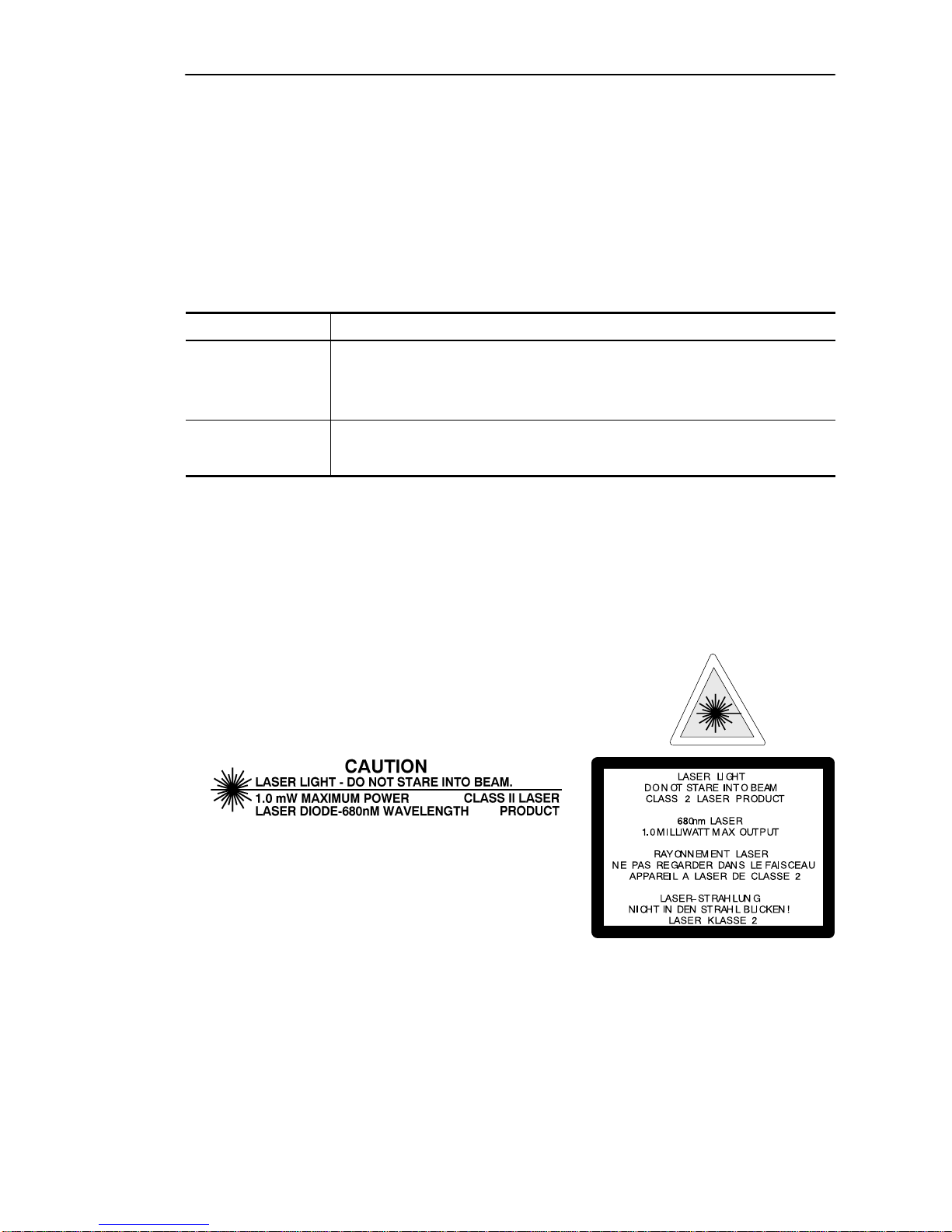
Laser Warning Symbol P–3. . . . . . . . . . . . . . . . . . . . . . . . . . . . . . . .
Chapter 1 Scanner Features
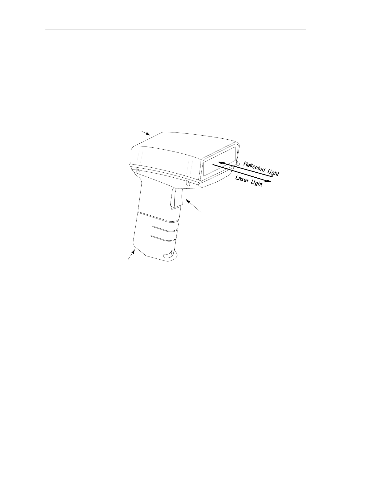
ScannerFeatures 1–2. . . . . . . . . . . . . . . . . . . . . . . . . . . . . . . . . . .
LED Indicators 1–3. . . . . . . . . . . . . . . . . . . . . . . . . . . . . . . . . . . . .
ConfigurationOptions 1–4. . . . . . . . . . . . . . . . . . . . . . . . . . . . . . . .
Decoding 1–4. . . . . . . . . . . . . . . . . . . . . . . . . . . . . . . . . . . . . . . . .
SafetyLabels 1–5. . . . . . . . . . . . . . . . . . . . . . . . . . . . . . . . . . . . . .
ScanningRanges 1–6. . . . . . . . . . . . . . . . . . . . . . . . . . . . . . . . . . .
Accessories 1–8. . . . . . . . . . . . . . . . . . . . . . . . . . . . . . . . . . . . . . .
Chapter 2 Connecting and Operating Scanner
Overview 2–2. . . . . . . . . . . . . . . . . . . . . . . . . . . . . . . . . . . . . . . . .
Scanner to Synapse Cable or AdaptaScan Pass Through Cable 2–3. .
Scanner Cable to Synapse Cable Connection 2–4. . . . . . . . . . . . . . .
Scanner Emulation Synapse Cable Connections 2–5. . . . . . . . . . . . .
RS-232 Synapse Cable Connection 2–6. . . . . . . . . . . . . . . . . . . . . .
Keyboard Wedge Synapse Cable Connections 2–8. . . . . . . . . . . . . .
AdaptaScan Pass Through Cable Connection 2–10. . . . . . . . . . . . . . .
Connecting Scanner to Enhanced Decoder Scanner Port 2–12. . . . . . .
Connecting Scanner to Enhanced Decoder Aux Port 2–13. . . . . . . . . .
Connecting Scanner to Flexible Interface (RB) Module 2–14. . . . . . . . .
Connecting Scanner to a PLC 2–15. . . . . . . . . . . . . . . . . . . . . . . . . .
Connecting Scanner to an SLC 2–16. . . . . . . . . . . . . . . . . . . . . . . . .
Operating the Scanner 2–17. . . . . . . . . . . . . . . . . . . . . . . . . . . . . . . .
AutomaticShutoff 2–18. . . . . . . . . . . . . . . . . . . . . . . . . . . . . . . . . . .
AudibleResponse 2–18. . . . . . . . . . . . . . . . . . . . . . . . . . . . . . . . . . .
Configuringthe Scanner and Synapse Cables 2–20. . . . . . . . . . . . . . .

toc–ii
Publication2755-6.2
Chapter 3 Configuring the Scanner
Important Notes on Configuring a Scanner 3–1. . . . . . . . . . . . . . . . .
Scanner Configuration Bar Codes 3–1. . . . . . . . . . . . . . . . . . . . . . . .
Configuringthe Scanner 3–2. . . . . . . . . . . . . . . . . . . . . . . . . . . . . .
Scanner Default Settings 3–2. . . . . . . . . . . . . . . . . . . . . . . . . . . . . .
Select Cable Type 3–4. . . . . . . . . . . . . . . . . . . . . . . . . . . . . . . . . . .
SelectSymbologies 3–4. . . . . . . . . . . . . . . . . . . . . . . . . . . . . . . . . .
UPC / EAN Options 3–5. . . . . . . . . . . . . . . . . . . . . . . . . . . . . . . . . .
CodabarOptions 3–8. . . . . . . . . . . . . . . . . . . . . . . . . . . . . . . . . . . .
Code 39 Options 3–9. . . . . . . . . . . . . . . . . . . . . . . . . . . . . . . . . . . .
MSI Plessey Options 3–11. . . . . . . . . . . . . . . . . . . . . . . . . . . . . . . . .
I 2-of-5 and Discrete 2-of-5 Options 3–12. . . . . . . . . . . . . . . . . . . . . .
Data Format Options 3–13. . . . . . . . . . . . . . . . . . . . . . . . . . . . . . . . .
Laser Control and Audible Response Options 3–17. . . . . . . . . . . . . . .
Chapter 4 Communication Setup (Cable Configuration)
CableDefaults 4–1. . . . . . . . . . . . . . . . . . . . . . . . . . . . . . . . . . . . .
Setting RS-232 Synapse Cable Options 4–2. . . . . . . . . . . . . . . . . . .
Setting IBM PC Keyboard Wedge Synapse Cable Options 4–9. . . . . .
Setting DEC VT520 Wedge Synapse Cable Options 4–13. . . . . . . . . . .
Setting DEC VT220 / VT320 / VT420 Wedge Synapse
CableOptions 4–16. . . . . . . . . . . . . . . . . . . . . . . . . . . . . . . . . . .
Setting Scanner Emulation Synapse Cable Options 4–19. . . . . . . . . . .
Setting AdaptaScan Pass Through Cable Options 4–24. . . . . . . . . . . .
Chapter 5 Troubleshooting and Maintenance
Troubleshootingthe Scanner 5–2. . . . . . . . . . . . . . . . . . . . . . . . . . .
Cleaning the Scan Window 5–4. . . . . . . . . . . . . . . . . . . . . . . . . . . .

toc–iii
Publication2755-6.2
Appendix A Specifications
Appendix B Hands-Free Stand Operation
Appendix C Scanner Pinout Connections
Appendix D ASCII Chart
Appendix E European Union Directive Compliance
Glossary

Preface
Publication2755-6.2
Using this Manual
Read this preface to familiarize yourself with the rest of the manual.
This preface covers the following topics:
•intended audience
•chapter contents
•laser warning symbol
•related publications
Intended Audience
No special knowledge is required to understand this document or use the
scanner. Decoded scanners may be connected to a variety of host
devices. We assume you are familiar with the host’s communication
ports.
Important: You will need the Bar Code Programming Guide for
Decoded Hand-Held Scanners (Publication 2755-6.5) to configure the
scanner and interface cables.

Using this ManualP-2
Publication2755-6.2
Contents of this Manual
The following table briefly describes the contents of each section.
Chapter Title Contents
Preface Using this Manual Describes the purpose, background, and scope
of this manual. Also provides a list of related
publications.
1Scanner Features Overview of the scanner. Includes read range
charts and description of accessory items.
2Connecting and Operating
the Scanner Describes how to connect the scanner to a host
device. Operating tips are also provided.
3Configuring the Scanner Describes how to configure the scanner using
the bar codes provided in the Bar Code
Programming Guide.
4Communication Setup
(Cable Configuration)
Describes how to configure the scanner cables
using the bar codes provided in the Bar Code
Programming Guide.
Appendix A Specifications Provides physical, electrical and environmental
specifications.
Appendix B Hands-Free Stand
Operation Describes scanner automatic operation when
using the adjustable stands.
Appendix C Scanner Connector
Pinouts Provides scanner pinout signal names and a
brief description of each.
Appendix D ASCII Chart ASCII conversion chart also provides Code 39
Full ASCII encoded characters.
Appendix E European Union Directive
Compliance Provides requirements for scanners when used
within the European Union.
Glossary Provides definitions of commonly used
teminology.
Inside Back
Cover Bar Code Test Symbols Sample symbols useful for testing the operation
of your bar code system.

Using this Manual P-3
Publication2755-6.2
Related Publications
Below is a list of related publications you may need to refer to when
using the scanner.
Publication No. Title
2755-6.5 Bar Code Programming Guide
Provides the configuration bar codes for the decoded scanner and
interface cables.
2755-921 Bar Code Basics
Describes bar code symbologies, equipment, and typical applications.
Laser Warning Symbol
Be aware of the following laser caution symbol.

Chapter 1
Publication2755-6.2
Scanner Features
This chapter describes the features of the decoded scanner.
Included are descriptions of:
•major features
•LEDs
•scanning ranges
•configuration options
•decoding
•safety labels
•accessories

Scanner Features1-2
Publication2755-6.2
Scanner Features
The scanners use a low power visible (red) laser diode for scanning. The
trigger turns on the laser which scans a label at approximately 36 scans
per second.
Trigger
Cable Connector
LEDs
The laser beam:
-exits through the scan window
-reflects off the label back through the window
-is detected by a sensor in the scanner
When a label is read, the laser beam is automatically turned off until the
trigger is pressed again. If no label is read, the laser beam automatically
turns off after 0.5 to 3 seconds (timeout is adjustable) and remains off
until the trigger is released and pressed again.
Note: When used with the adjustable stands (Catalog No.
2755-HFN-K1, -K2), the scanner operates automatically for hands-free
operation. Refer to Appendix B.

Scanner Features 1-3
Publication2755-6.2
LED Indicators
On the back of the scanner there is a clear window through which two
LEDs are visible.
Green Red
Green LED = Decode, indicating that a bar code symbol has been
scanned and decoded. LED remains on until the next scan
(trigger pressed).
Red LED = Scanning, indicating that the laser light is on.

Scanner Features1-4
Publication2755-6.2
Configuration Options
The scanner is readily adaptable to a wide variety of applications by
scanning configuration bar codes. The configuration bar codes control
the operation of:
•decoding
•laser light
•communications
Chapters 3 and 4 describe the configuration options.
Decoding
The scanner can decode the following symbologies:
•UPC-A •UPC-E
•EAN 8 •EAN 13
•Codabar •Code 39
•Code 39 Full ASCII •Discrete 2 of 5
•Interleaved 2 of 5 •Code 128
•MSI Plessey •Code 93
•EAN 128
The scanner is autodiscriminating so that multiple symbologies may be
enabled at the same time. The only exception is the scanner cannot
discriminate between Code 39 and Code 39 Full ASCII.

Scanner Features 1-5
Publication2755-6.2
Safety Labels
The scanners use a low power visible laser diode. As with any bright
light source, you should avoid staring directly into the beam.
Momentary exposure to a CDRH Class II laser is not known to be
harmful.
The following figure shows the location of all safety labels as they
appear on the scanner.
AVOID EXPOSURE
LASER LIGHT IS
EMITTED FROM
THIS APERATURE.
LASER LIGHT
DO NOT STARE INTO BEAM
CLASS 2 LASER PRODUCT
680nm LASER
1.0 MILLIWATT MAX OUTPUT
RAYONNEMENT LASER
NE PAS REGARDER DANS LE FAISCEAU
APPAREIL A LASER DE CLASSE 2
LASER–STRAHLUNG
NICHT IN DEN STRAHL BLICKEN !
LASER KLASSE 2
COMPLIES WITH
IEC 825–1:1993/EN 60825
CAUTION – LASER LIGHT WHEN OPEN –
DO NOT STARE INTO BEAM.
ATTENTION – RAYONNEMENT LASER EN
CAS DOUVERTURE. NE PAS REGARDER
DANS LE FAISCEAU
VORSICHT!
LASERSTRAHL, WENN ABDECKUNG GEOEFFNET
Appears on both sides.

Scanner Features1-6
Publication2755-6.2
Scanning Ranges
The scanner can read bar code symbols at various distances depending
upon the bar code width (width of bars or spaces).
Minimum Bar Code
Width
Read Range
(Catalog No. 2755-HDG4)
Inches / Centimeters
4.0 mil
(.13 mm) 1.5 in to 2.0 in
(3.8 cm to 5.1 cm)
5.0 mil
(.13 mm) 1.25 in to 3.25 in
(3.2 cm to 8.2 cm)
7.5 mil
(.19 mm) 0.0 in to 7.0 in
(0.0 cm to 17.8 cm)
20.0 mil
(.51 mm) 0.0 in to 25.0 in
0.0 cm to 63.5 cm)
40.0 mil
(1.02 mm) 2.0 in to 40.0 in
(5.1 cm to 101.6 cm)
55.0 mil
(1.40 mm) 3.0 in to 55.0 in
(7.6 cm to 140 cm)

Scanner Features 1-7
Publication2755-6.2
0
30 35
0
5 (12.7 cm)
10 (25.4 cm)
40 mil
5 mil
Distance From Front of Scanner
76 89
inches
centimeters 252015105
7.5 mil
(0.19 mm)
(1.02 mm)
(0.13 mm)
12.7 25 38 51 64
Decoded Scanner
Catalog No. 2755-HDG-4
Scanner
5 (12.7 cm)
10 (25.4 cm)
40
102
55 mil
(1.40 mm)
Scan Width
20 mil
(0.51 mm)
Scanner
45
114 50
127 55
140
15 (38.1 cm)
20 (50.8 cm)
15 (38.1 cm)
20 (50.8 cm)
4 mil
(0.10 mm)

Scanner Features1-8
Publication2755-6.2
Accessories
The following accessories are available.
Scanner Cables – Connects scanner to Synapse
cable. See page 2–3 for connections.
•8 ft. / 2.44 meter
(Catalog No. 2755-HDC-GS1-08)
•20 ft. / 6.1 meter
(Catalog No. 2755-HDC-GS1-20)
RS-232 Synapse Cables – Provide RS-232
output. Cables are configurable.
See page 2-7 for connections.
•RS-232-C, 25-pin DB, male, Txd on Pin 3
(Catalog No. 2755-HFC-SR2-01)
•RS-232-C, 9-pin DB, female, Txd on Pin 2
(Catalog No. 2755-HFC-SR3-01)

Scanner Features 1-9
Publication2755-6.2
Power Supplies –Connect to RS-232, keyboard
wedge or scanner emulation Synapse cable.
Provides power for the scanner ➀.
•100 - 240 VAC, 50 - 60 Hz
(Catalog No. 2755-HFP-D1)
•Power cable for power supply, IEC 320,
terminated, US 110V AC
(Part No. 77121-801-01)
•Power cable for power supply, IEC 320,
unterminated, US 240V AC
(Part No. 77121-801-02)
•Power cable for power supply, IEC 320,
unterminated, European 240V AC
(Part No. 77121-801-03)
➀ Some applications may not require a power supply when the host provides adequate
power for the scanner. This ability of the host to power the scanner will vary with
system configurations. The scanner with cable requires 150 mA at 5 volts (typical).
Keyboard Wedge Synapse Cables –Connects
between keyboard and host device. Host device
receives decoded bar code data the same as
keyboard input. See page 2–8 for connections.
•For IBM XT/AT keyboard, 5-pin DIN
(Catalog No. 2755-HFC-SP1-01)
•For PS/2 keyboard, 6-pin Mini-DIN
(Catalog No. 2755-HFC-SP2-01)
•For DEC VT220, 320, 420 keyboards
(Catalog No. 2755-HFC-SV1-01)
•For DEC VT520 keyboards
(Catalog No. 2755-HFC-SV2-01)

Scanner Features1-10
Publication2755-6.2
Scanner Emulation Synapse Cable –Provides
undecoded scanner output. See page 2-12 for
connections.
•(Catalog No. 2755-HFC-SA1-01)
AdaptaScan Pass Through Cable –Connects
scanner to custom cable for connection to
AdaptaScan RS-232 and power terminal blocks.
See page 2-10 for connections.
•RS-232-C, 25-pin DB, male, Txd on Pin 3
(Catalog No. 2755-HDC-GA2-08)
Adjustable Stands –Provide hands-free
operation. When placed into the stand, the
scanner automatically turns on and remains on
in a blinking mode. Any symbol passed under
the scan line is decoded. Has separate
adjustments for scanner angle and height.
•5 to 18 inch (127 to 457 mm) height
(Catalog No. 2755-HFN-K1)
•9 to 16 inch (229 to 406 mm) height
(Catalog No. 2755-HFN-K2)

Scanner Features 1-11
Publication2755-6.2
Multi-mount Stand –Rubber coated, fixed
mount holder for counter or wall mounting.
The stand has the following approximate
dimensions: 3.5 x 4.0 x 6.5 inches (89 x 102 x
165 mm).
•(Catalog No. 2755-HFN-K3)
Protective Boot –Heavy canvas boot provides
additional protection for the scanner.
•(Catalog No. 2755-HFN-H1)

Chapter 2
Publication2755-6.2
Connecting and Operating
Scanner
This chapter describes how to connect and test the operation of the
scanner. Sections include:
•Scanner cable
•Scanner Emulator Synapse cable connections
•RS-232 Synapse cable connections
•Keyboard Wedge Synapse cable connections
•AdaptaScan Pass Through cable connections
•Allen-Bradley Enhanced Decoder applications
•Flexible Interface Module (RB) application
•PLC application
•SLC application
Safety
!ATTENTION: Caution - use of controls or
adjustments or performance of procedures other than
those specified herein may result in hazardous laser
light exposure.
Table of contents
Other Allen-Bradley Barcode Reader manuals

Allen-Bradley
Allen-Bradley Bulletin 2755 User manual

Allen-Bradley
Allen-Bradley StrataScan 2755-LHR-5B User manual

Allen-Bradley
Allen-Bradley DS Series User manual

Allen-Bradley
Allen-Bradley 2-D User manual

Allen-Bradley
Allen-Bradley 2755-HUG-4 User manual

Allen-Bradley
Allen-Bradley 2755-LS7-SB User manual

Allen-Bradley
Allen-Bradley 2755-SN3 User guide

Allen-Bradley
Allen-Bradley 2755-HTG-4 Operating instructions