Allen-Bradley 2755-HUG-4 User manual

User
Manual
Hand-Held
Undecoded Bar
Code Scanner
Cat. No. 2755-HUG-4,
2755-HUG-9
Allen-Bradley

Publication2755-6.1
Important User Information
Because of the variety of uses for the products described in this publication,
those responsible for the application and use of this control equipment must
satisfy themselves that all necessary steps have been taken to assure that each
application and use meets all performance and safety requirements, including
any applicable laws, regulations, codes and standards.
The illustrations, charts, sample programs and layout examples shown in this
guide are intended solely for purposes of example. Since there are many
variables and requirements associated with any particular installation,
Allen-Bradley does not assume responsibility or liability (to include intellectual
property liability) for actual use based upon the examples shown in this
publication.
Allen-Bradley publication SGI-1.1, Safety Guidelines for the Application,
Installation, and Maintenance of Solid-State Control (available from your local
Allen-Bradley office), describes some important differences between solid-state
equipment and electromechanical devices that should be taken into consideration
when applying products such as those described in this publication.
Reproduction of the contents of this copyrighted publication, in whole or in part,
without written permission of Allen-Bradley Company, Inc., is prohibited.
Throughout this manual we use notes to make you aware of safety
considerations:
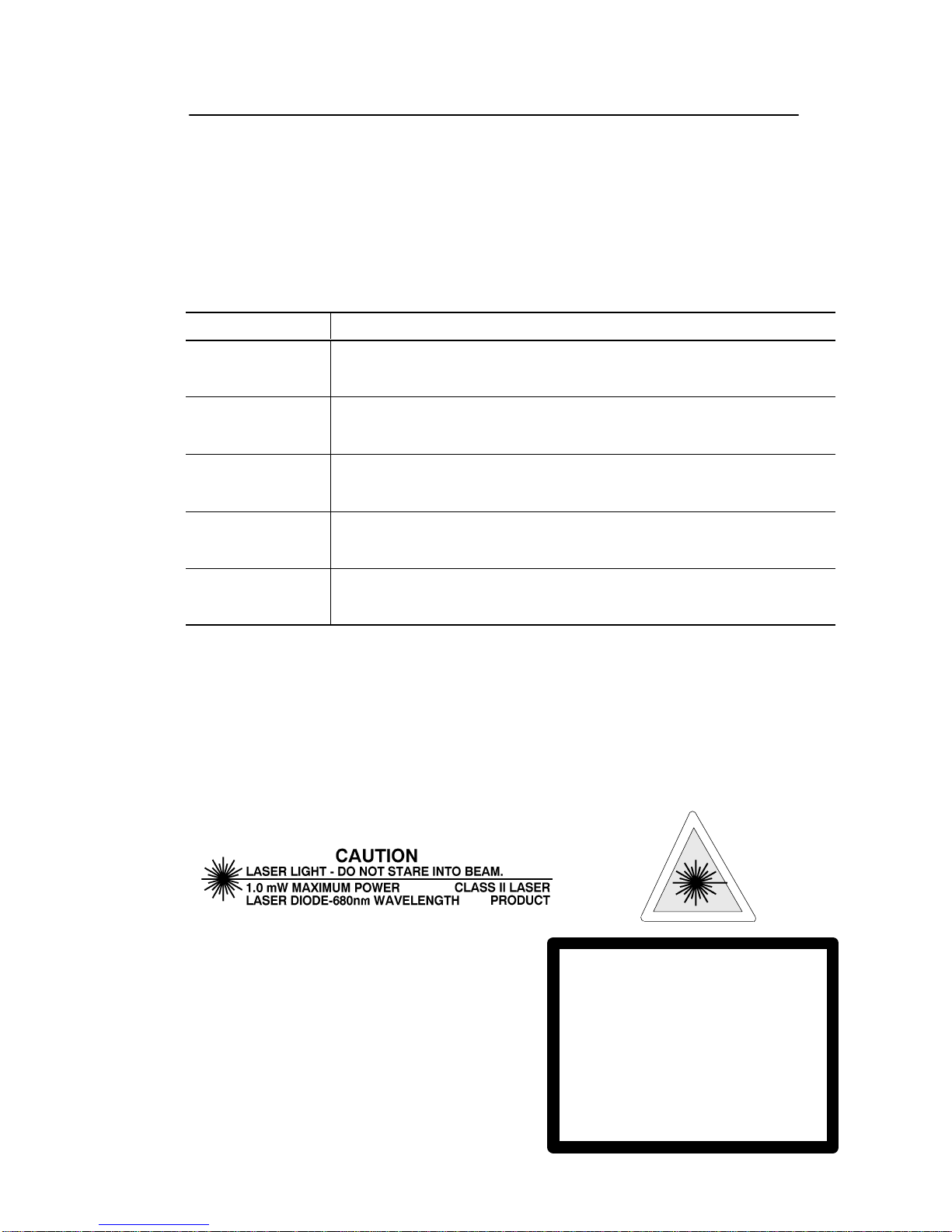
!ATTENTION: Identifies information about practices or
circumstances that can lead to personal injury or death,
property damage or economic loss.
Attention statements help you to:
•identify a hazard
•avoid the hazard
•recognize the consequences
Important: Identifies information that is critical for successful application and
understanding of the product.

Table of Contents
Publication2755-6.1
Preface
IntendedAudience P–1. . . . . . . . . . . . . . . . . . . . . . . . . . . . . . . . . .
Contents of this Manual P–2. . . . . . . . . . . . . . . . . . . . . . . . . . . . . . .
RelatedPublications P–3. . . . . . . . . . . . . . . . . . . . . . . . . . . . . . . . .
Laser Warning Symbol P–3. . . . . . . . . . . . . . . . . . . . . . . . . . . . . . . .
Chapter 1 Scanner Features
ScannerFeatures 1–2. . . . . . . . . . . . . . . . . . . . . . . . . . . . . . . . . . .
LED Indicators 1–3. . . . . . . . . . . . . . . . . . . . . . . . . . . . . . . . . . . . .
SafetyLabels 1–4. . . . . . . . . . . . . . . . . . . . . . . . . . . . . . . . . . . . . .
ScanningRanges 1–5. . . . . . . . . . . . . . . . . . . . . . . . . . . . . . . . . . .
Standard Range Scanner (Catalog No. 2755-HUG-4) 1–6. . . . . . . .
Extended Range Scanner (Catalog No. 2755-HUG-9) 1–7. . . . . . .
Accessories 1–8. . . . . . . . . . . . . . . . . . . . . . . . . . . . . . . . . . . . . . .
Chapter 2 Connecting and Operating Scanner
CompatibleDecoders 2–1. . . . . . . . . . . . . . . . . . . . . . . . . . . . . . . .
ScannerCable 2–2. . . . . . . . . . . . . . . . . . . . . . . . . . . . . . . . . . . . .
Connecting the Scanner to a Decoder 2–3. . . . . . . . . . . . . . . . . . . . .
Operating the Scanner 2–5. . . . . . . . . . . . . . . . . . . . . . . . . . . . . . . .
Spotter Beam 2–6. . . . . . . . . . . . . . . . . . . . . . . . . . . . . . . . . . . . . .
AutomaticShutoff 2–6. . . . . . . . . . . . . . . . . . . . . . . . . . . . . . . . . . .
AudibleResponse 2–6. . . . . . . . . . . . . . . . . . . . . . . . . . . . . . . . . . .
OperatingTips 2–7. . . . . . . . . . . . . . . . . . . . . . . . . . . . . . . . . . . . .

toc–ii
Publication2755-6.1
Chapter 3 Troubleshooting and Maintenance
Troubleshootingthe Scanner 3–2. . . . . . . . . . . . . . . . . . . . . . . . . . .
Cleaning the Scan Window 3–4. . . . . . . . . . . . . . . . . . . . . . . . . . . .
Specifications
Appendix A
Connector Pinouts
Appendix B
European Union Directive Compliance
Appendix C
Glossary

Preface
Publication2755-6.1
Using this Manual
Read this preface to familiarize yourself with the rest of the manual.
This preface covers the following topics:
•intended audience
•chapter contents
•laser warning symbol
•related publications
Intended Audience
No special knowledge is required to understand this document or to use
the scanner. Undecoded scanners require a decoder. We assume that you
are familiar with the operation and cable inputs to your decoder.

P–2
Publication2755-6.1
Contents of this Manual
The following table briefly describes the contents of each section.
Chapter Title Contents
Preface Using this Manual Describes the purpose, background, and scope
of this manual. Also provides a list of related
publications.
1Scanner Features Overview of the scanner. Includes read range
charts and description of accessory items.
2Connecting and Operating
the Scanner Describes how to connect the scanner to a
decoder. Operating tips are also provided.
3Troubleshooting and
Maintenance
Provides solutions to the most common
operating problems. Also includes instructions
on cleaning the scan window.
Appendix A Specifications Provides physical, electrical and environmental
specifications.
Appendix B Scanner Connector
Pinouts Provides scanner pinout signal names and a
brief description of each.
Appendix C European Union
Compliance Directives Lists requirements for use of scanner within the
European Union.
Glossary Provides definitions for commonly used
terminology.
Inside Back
Cover Bar Code Test Symbols Sample symbols useful for testing the operation
of your bar code system.

P–3
Publication2755-6.1
Related Publications
Below is a list of related publications you may need to refer to when
using the scanners.
Publication No. Title
2755-921 Bar Code Basics
Describes bar code symbologies, equipment, and typical applications.
2755-833 User Manual for
DS/DD Series B Enhanced Decoders
2755-ND010 User Manual for
Single-Head Enhanced Decoder (Catalog No. 2755-DS1A)
2755-ND011 User Manual for
Dual-Head Enhanced Decoder (Catalog No. 2755-DD1A)
2755-2.37 Product Data Sheet for
Bulletin 2755 Gun Adapter (Catalog No. 2755-NC16)
Laser Warning Symbol
Be aware of the following laser caution symbols.
LASER LIGHT
DO NOT STARE INTO BEAM
CLASS 2 LASER PRODUCT
680nm LASER
1.0 MILLIWATT MAX OUTPUT
RAYONNEMENT LASER
NE PAS REGARDER DANS LE FAISCEAU
APPAREIL A LASER DE CLASSE 2
LASER–STRAHLUNG
NICHT IN DEN STRAHL BLICKEN !
LASER KLASSE 2

Chapter 1
Publication2755-6.1
Scanner Features
This chapter describes the features of the standard and extended range,
undecoded scanners. Included are descriptions of:
•major features
•LEDs
•scanning ranges
•safety labels
•accessories

1–2
Publication2755-6.1
Scanner Features
The scanners use a low power visible (red) laser diode for scanning. The
trigger turns on the laser which scans a label at approximately 36 scans
per second.
Trigger
Cable Connector
LEDs
The laser beam:
-exits through the scan window
-reflects off the label back through the window
-is detected by a sensor in the scanner
When a label is read, the laser beam is automatically turned off until the
trigger is pressed again. If no label is read, the laser beam automatically
turns off after approximately 3 seconds and remains off until the trigger
is released and pressed again.
Note: The Extended Range Scanner (Catalog No. 2755-HUG-9) has a
two position trigger. The first detent provides a spotter beam and the
second position provides a scan line.

1–3
Publication2755-6.1
LED Indicators
On the back of the scanner there is a clear window through which two
LEDs are visible.
Green Red
Green LED = Good Read, indicating that a bar code symbol has been
scanned and decoded. LED remains on until the next scan
(trigger pressed).
Red LED = Scanning, indicating that the laser light is on.

1–4
Publication2755-6.1
Safety Labels
The scanners use a low power visible laser diode. As with any bright
light source, you should avoid staring directly into the beam.
Momentary exposure to a CDRH Class II laser is not known to be
harmful.
The following figure shows the location of all safety labels as they
appear on the scanner.
AVOID EXPOSURE
LASER LIGHT IS
EMITTED FROM
THIS APERATURE.
LASER LIGHT
DO NOT STARE INTO BEAM
CLASS 2 LASER PRODUCT
680nm LASER
1.0 MILLIWATT MAX OUTPUT
RAYONNEMENT LASER
NE PAS REGARDER DANS LE FAISCEAU
APPAREIL A LASER DE CLASSE 2
LASER–STRAHLUNG
NICHT IN DEN STRAHL BLICKEN !
LASER KLASSE 2
COMPLIES WITH
IEC 825–1:1993/EN 60825
CAUTION –LASER LIGHT WHEN OPEN –
DO NOT STARE INTO BEAM.
ATTENTION –RAYONNEMENT LASER EN
CAS DOUVERTURE. NE PAS REGARDER
DANS LE FAISCEAU
VORSICHT!
LASERSTRAHL, WENN ABDECKUNG GEOEFFNET
Appears on both sides.

1–5
Publication2755-6.1
Scanning Ranges
The scanners can read bar code symbols at various distances depending
upon the bar code symbol density (width of narrow bars or spaces). The
following table lists the read ranges for both the standard and extended
range scanners.
Minimum
Symbol
Density
Standard Range
(Catalog No. 2755-HUG4)
Inches / Centimeters
Extended Range
(Catalog No. 2755-HUG9)
Inches / Meters
5.0 mil
(.13 mm) 1.25 in to 2.7 in
(3.2 cm to 6.9 cm) Not Applicable
7.5 mil
(.19 mm) 1.0 in to 7.0 in
(2.5 cm to 17.8 cm) 5.0 in to 11 in
(0.13 m to 0.28 m)
10.0 mil
(.25 mm) Data Not Available 4.0 to 13 in
(0.10 m to 0.33 m)
15.0 mil
(.38 mm) Data Not Available 4.0 to 60 in
( 0.10 m to 1.52 m)
20.0 mil
(.51 mm) 1.0 in to 27 in
(2.5 cm to 69 cm) 5.0 to 65 in
(0.13 m to 1.65 m)
40.0 mil
(1.02 mm) 4.5 in to 37 in
(11.4 cm to 94 cm) 14 in to 120 in
(0.36 m to 3.05 m)
55.0 mil
(1.40 mm) 7 in to 50 in
(17.8 cm to 127 cm) 24 in to 156 in
(0.61 m cm to 3.96 m)
70.0 mil
(1.78 mm)
Reflective Not Applicable 96 in to 276 in
2.43 m to 7.01 m
100 mil
(1.02 mm)
Reflective Not Applicable 96 in to 420 in
(2.44 m to 10.67 m)

1–6
Publication2755-6.1
0
30 35
0
5 (12.7 cm)
10 (25.4 cm)
40 mil
5 mil
Distance From Front of Scanner
76 89
inches
centimeters 252015
105
7.5 mil
(0.19 mm)
(1.02 mm)
(0.13 mm)
12.7 25 38 51 64
Standard Range Scanner
Catalog No. 2755-HUG4
Scanner
5 (12.7 cm)
10 (25.4 cm)
40
102
55 mil
(1.40 mm)
Scan Width
20 mil
(0.51 mm)
Scanner
50
127

1–7
Publication2755-6.1
0
300 350
0
25 in (63.5 cm)
50 in (127 cm)
55.0mil
15.0mil
Distance From Front of Scanner
762 889
inches
centimeters 250200150
10050
20.0mil
(0.51mm)
(1.40 mm)
(0.38 mm)
127 254 381 508 635
Extended Range Scanner
Catalog No. 2755-HUG9
Scanner
25 in (63.5 cm)
50 in (127 cm)
420
1067
70.0milReflective
(1.78 mm)
100 mil Reflective
(2.54 mm)
Scan Width
See Inset
Inset
40 mil
(1.02 mm)
Scanner
Scan Width
inches
centimeters 1196
3
7.6 15.2 22.9 27.9 13
33.0
0
0
1.5 in (3.8 mm)
3 in (7.8cm)
3 in (7.8cm)
1.5 in (3.8 mm)
7.5 mil
(.19 mm)
10 mil
(0.25 mm)

1–8
Publication2755-6.1
Accessories
The following accessories are available.
Scanner Cables – Connect scanner to A-B
decoder. See page 2–2 for connections.
•8 ft. / 2.44 meter
(Catalog No. 2755-HUC-GA1-08)
•15 ft. / 4.57 meter
(Catalog No. 2755-HUC-GA1-15)
•20 ft. / 6.1 meter
(Catalog No. 2755-HUC-GA1-20)
Adjustable Stands – Holds scanner at adjustable
angles and heights for hand-free scanner
operation.
•5 to 18 inch (127 to 457 mm) height
(Catalog No. 2755-HFN-K1)
•9 to 16 inch (229 to 406 mm) height
(Catalog No. 2755-HFN-K2)
Multi-mount Stand – Rubber-coated, fixed
mount holder for counter or wall mounting.
•(Catalog No. 2755-HFN-K3)
Protective Boot – Heavy canvas boot provides
additional protection for the scanner.
•(Catalog No. 2755-HFN-H1)

Chapter 2
Publication2755-6.1
Connecting and
Operating Scanner
This chapter describes how to connect and test the operation of the
scanner. Sections include:
•compatible decoding devices
•installing / removing the interface cable
•connecting to a decoder
•operating scanner
Safety
!ATTENTION: Caution - use of controls or
adjustments or performance of procedures other than
those specified herein may result in hazardous laser
light exposure.
Compatible Decoders
The undecoded scanners are compatible with the following
Allen-Bradley decoders:
•Bulletin 2708-DH5 Attended Workstations
•Multi-Purpose Bar Code WorkStation
(Catalog No. 2755-DH1)
•Single or Dual-Head Enhanced Bar Code Decoder
(Catalog No. 2755-DD1x, -DS1x)

2–2
Publication2755-6.1
Scanner Cable
The scanner cables connect to the bottom of the scanner handle.
See page 1–8 for lengths available.
Connector
Slot for Locking Collar
Cable Connector
Locking Collar
To attach the scanner cable to the scanner.
1. Pull back the locking collar from the connector.
2. Insert the cable connector into the scanner.
3. Align the tabs on the locking collar with the slots on the handle.
4. Push in and turn the locking collar counterclockwise to lock.
Connector is locked when flat edge of locking collar aligns with the
flat edge of the scanner handle.
Remove a scanner cable by rotating the locking collar clockwise until the
cable can be pulled out of the scanner.

2–3
Publication2755-6.1
Connecting the Scanner to a Decoder
The scanner interface cable connects to the input port of the decoder.
The following table summarizes the cable and connectors required for
each decoder.
Note: A Gun Adapter (Catalog No. 2755-NC16)
may be required to connect the scanner to some
Series B decoders.
Decoder Type
2755-NC16
Series B
Gun Adapter
Bulletin 2708-DH5
Attended WorkStations No
Multi-Purpose
Bar Code WorkStation
(Catalog No. 2755-DH1) No
Single or Dual-Head
Enhanced Bar Code Decoder
(Catalog No. 2755-DS1A, -DD1A) Required
!ATTENTION: Do not install or remove the scanner
cables or connectors until the power to the scanner and
decoder is turned off. Failure to follow this caution may
result in damage to the scanner or decoder.
!ATTENTION: Make sure you use the Series B Gun
Adapter (Catalog No. 2755-NC16, Series B). If you are
ugrading from an earlier version Allen-Bradley hand-held
scanner (such as the 2755-G2 or -G3) which used the
Series A gun adapter, you will need to purchase the series
B gun adapter.

2–4
Publication2755-6.1
The 2755-NC16 Gun Adapter connects to the decoder input port as
shown below for the Enhanced Decoder, the High Speed Decoder is
similar.
Gun Adapter

2–5
Publication2755-6.1
Operating the Scanner
1. Check your connections.
•Is the scanner cable securely attached?
•If connecting to a High Speed or Enhanced
decoder, is the Gun Adapter present?
•Is power applied to the decoder?
2. Test the scanner
Aim the scanner at the work
surface and press the trigger.
You should see the red beam
on the work surface, and the
red LED on the back of the
scanner should be on.
3. Scan a label.
Scan a bar code. Adjust the
scanner position so that the scan
beam is centered on the bar
code and overlaps both sides.
When the scanner has read a
symbol:
•You will hear a beep from the
decoder (if enabled).
•The green LED will turn on
and remain on until the next
scan.
This manual suits for next models
1
Table of contents
Other Allen-Bradley Barcode Reader manuals

Allen-Bradley
Allen-Bradley Bulletin 2755 User manual

Allen-Bradley
Allen-Bradley StrataScan 2755-LHR-5B User manual

Allen-Bradley
Allen-Bradley 2-D User manual

Allen-Bradley
Allen-Bradley DS Series User manual

Allen-Bradley
Allen-Bradley 2755-HTG-4 Operating instructions

Allen-Bradley
Allen-Bradley 2755-SN3 User guide

Allen-Bradley
Allen-Bradley 2755-HDG-4 User manual

Allen-Bradley
Allen-Bradley 2755-LS7-SB User manual