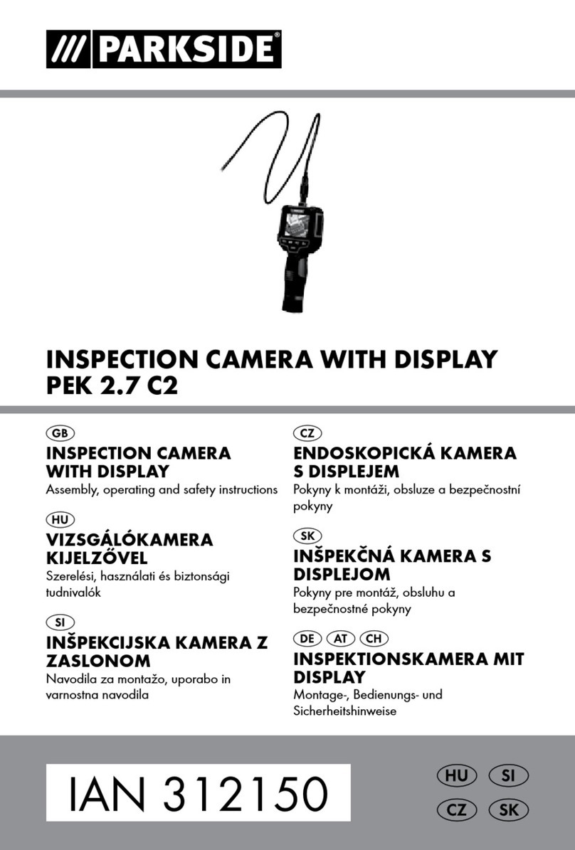
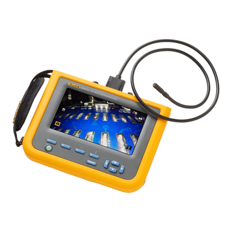
Alliance Technology Vutek GT Series User manual

1 of 16
An Alliance Technology Company
600 Dekora Woods Blvd. Saukville, WI 53080
Toll Free: 800-488-8177 Local: 262-268-9330 Fax: 262-268-9952
An Alliance Technology Company

2 of 16
An Alliance Technology Company
600 Dekora Woods Blvd. Saukville, WI 53080
Toll Free: 800-488-8177 Local: 262-268-9330 Fax: 262-268-9952
An Alliance Technology Company
TABLE OF CONTENTS
Revised on: May 21, 2012.
Warranty……………………………….page 2
Command Module……………………page 5
Remote…………………………………page 9
BaseFrame…………………………….page 10
Camera…………………….…………...page 12

3 of 16
An Alliance Technology Company
600 Dekora Woods Blvd. Saukville, WI 53080
Toll Free: 800-488-8177 Local: 262-268-9330 Fax: 262-268-9952
An Alliance Technology Company
1 YEAR WARRANTY
Alliance Technology, LLC warrants to the original purchaser that should any of its products prove to
be defective in material or workmanship in normal use, within one (1) year from the date of delivery,
Alliance Technology, LLC will, at its exclusive option, repair, replace or exchange the product or any
of its parts. THIS WARRANTY IS SUBJECT TO THE FOLLOWING LIMITATIONS:
1. The warranty does not apply to any product which has been subject to accident, negligence,
alteration, abuse, misuse, overload, repair by anyone other than Alliance Technology, LLC or its
authorized representatives, or not maintained in accordance with the manufacturer's suggested
maintenance schedule.
2. The warranty applies only to components manufactured by Alliance Technology, LLC. The
appropriate manufacturer's warranty, if any, shall apply to components not manufactured by the
company.
3. The warranty does not apply to flex-link connectors, rod, LED light rings, cable, rollers, o-rings,
and skids, or other parts, which are considered consumable. The replacement of these items is
part of normal product maintenance.
4. The warranty shall not apply if the products are used or operated in any manner not consistent
with their intended purpose.
5. The warranty is limited to repair or replacement of defective products and parts during the
warranty period, and shall be the exclusive remedy. Alliance Technology, LLC shall in no event
have any other obligation or liability of any nature arising from the breakdown, malfunction, defect
or other failure of the product, including, without limitation, any liability for service, maintenance,
repairs, personal injury, property damage, loss of profits, loss of use or other consequential
damages.
6. Any action for any claimed breach of this warranty shall be brought within one (1) year from the
date of delivery of the product.
7. The purchaser must return the defective product, part or component to the Alliance Technology,
LLC factory in Saukville, WI 53080 at the purchaser's expense, properly and adequately
packaged, with insurance and transportation pre-paid. Alliance Technology, LLC will either repair
or replace the defective product, part or component, at its option, and will return it to the
purchaser at the customer's expense. In no event shall Alliance Technology, LLC be liable for
delay in repair or replacement and return under this warranty. Alliance Technology, LLC will
endeavor to effect appropriate repairs in the shortest time practical, with respect to the customer
having beneficial use of their equipment.
8. Alliance Technology, LLC neither assumes nor authorizes any person to assume any other
liability or make any other warranty in connection with the products.
9. THIS WARRANTY IS EXPRESSLY GIVEN IN LIEU OF ALL OTHER WARRANTIES
EXPRESSED OR IMPLIED. ALLIANCE TECHNOLOGY, LLC EXPRESSLY DISCLAIMS ANY
OTHER WARRANTY, INCLUDING, WITHOUT LIMITATION, ANY WARRANTY OF
MERCHANTABILITY OR FITNESS FOR A PARTICULAR PURPOSE.

4 of 16
An Alliance Technology Company
600 Dekora Woods Blvd. Saukville, WI 53080
Toll Free: 800-488-8177 Local: 262-268-9330 Fax: 262-268-9952
An Alliance Technology Company
SETTING UP YOUR VuTEK INSPECTION SYSTEMS
SYSTEM MAINTENANCE REQUIREMENTS
The following maintenance procedures are recommended for all VuTek Systems. Standard
warranty policy dictates that components and accessories subject to wear and tear are not
covered under the One (1) year warranty. Therefore we are strongly recommending that all
systems be maintained according to the following procedures. Please be advised that VuTek
will not allow warranty coverage for these items if these procedures are not followed.
VuTek Command Module:
The VuTek CM incorporates a USB port as its standard recording device. This port has no
moving parts or recording heads so it does not require a cleaning device. However, if water,
dirt or dust become present in this connector due to extreme conditions in the field,
owners/operators will be responsible for the cleaning of the connector/port area using a Q-tip
or other non-abrasive cleaning tool to remove the debris before inserting a memory stick.
FAILURE TO FOLLOW THIS PROCEDURE INVALIDATES ANY WARRANTY
CLAIM AGAINST VUTEK FOR THE FUNCTIONALITY OF THE RECORDING
DEVICE AND WARRANTY COVERAGE WILL NOT BE GRANTED.
O-Rings: O-rings are critical to insure the watertight integrity of the camera and connection
areas. O-rings are subject to wear and tear and can also suffer failure due to age and other
factors. They should be inspected regularly and replaced whenever needed.
When O-rings are working properly, a small amount of water and sometimes fine particles of
grit will build up behind them. Any time the camera or sonde connection is taken apart and
exposed, there exists the risk of grit wearing down or possibly even tearing the o-ring. It is
also possible for water to then enter the connection area once exposed. All connections, once
opened or exposed, MUST be thoroughly cleaned and dried before re-connecting. We
recommend using an old toothbrush or other soft bristled brush to clean the o-ring areas and
remove the grit or fine debris. Then, completely dry the area around male and female
connector and the o-ring before re-connecting.
Camera Head: All VuTek camera heads (CV, CVSL and CVmicro) are covered for one (1)
year under the standard warranty against all defects in workmanship. These cameras are all
sealed and pressurized with nitrogen to prevent water ingress. Warranty coverage will apply

5 of 16
An Alliance Technology Company
600 Dekora Woods Blvd. Saukville, WI 53080
Toll Free: 800-488-8177 Local: 262-268-9330 Fax: 262-268-9952
An Alliance Technology Company
for any and all internal failures to the camera head unless external damage is evident. This
would include a broken sapphire window and any deformation to the stainless steel metal
housing of the camera head.
VuTek has provided a small and large protective skid that MUST be used at all times. These
skids are designed to aid in the centering of the camera head and have the added benefit of
helping to protect the camera head from extreme wear. Failure to use the provided skids will
result in the direct wear of the metal, especially at the front window array, resulting in the
eventual wearing down of the metal. This wear could result in a breach of the window seal
allowing water into the camera head. This type of wear will not be covered under warranty.
Push Rod: VuTek push rod terminations are covered for one (1) year under warranty. This
warranty policy covers workmanship on the termination connection ONLY and does not
cover push rod breakage or kinks in other parts of the rod.

6 of 16
An Alliance Technology Company
600 Dekora Woods Blvd. Saukville, WI 53080
Toll Free: 800-488-8177 Local: 262-268-9330 Fax: 262-268-9952
An Alliance Technology Company

7 of 16
An Alliance Technology Company
600 Dekora Woods Blvd. Saukville, WI 53080
Toll Free: 800-488-8177 Local: 262-268-9330 Fax: 262-268-9952
An Alliance Technology Company
MAIN SYSTEM CONTROLS
1. Brightness Up –Increase Camera Head
LED brightness - recommended to keep
this at full brightness.
2. Brightness Down –Decrease Camera Head
LED brightness.
3. System Power ON/OFF button. Red LED
indicates system is ON.
4. On-Screen Distance Counter Position.
Button will toggle distance counter to 6
positions on display.
5. On-Screen Distance Counter Reset.
Button will reset distance counter to zero.
6. LED System Indicators
a. Green “Charging On”LED
- ON Green - Full Charge
- BLINKING Green - Charging
- OFF Green - Not Charging
b. Yellow “Power Low”LED
- OFF Yellow - Normal
- 1/2 sec ON, 1/2 sec OFF - Power Low
- 1 sec ON, 1 sec OFF - System Fault
c. Blue “Mic On”LED
- ON Blue - Microphone ON
- OFF Blue - Microphone Off
7. Built-In Microphone and IR remote window
8. Microphone ON/OFF button. Blue “MIC”
LED and on-screen “MIC”appear when ON.

8 of 16
An Alliance Technology Company
600 Dekora Woods Blvd. Saukville, WI 53080
Toll Free: 800-488-8177 Local: 262-268-9330 Fax: 262-268-9952
An Alliance Technology Company
9. On-Demand Recording ON/OFF Button. Red
blinking LED indicates recorder is turning ON
and will be ready for use shortly. Green LED
indicates recorder is ON and is ready for use.
10. Speaker ON/OFF button. Sound playback
is available during video playback. Button
will toggle volume from lowest to highest.
(5 steps)
11. Built-In Speaker
12. MENU Button - Menu button brings up
the on-screen configuration menu.
Please call VuTek customer support
for assistance. Also doubles as a “soft”
key for on-screen display.
13. AUX Button - This button is used as a
“soft”key for on-screen display
14. TEXT WRITER Button - This button is used as a
“soft”key for on-screen display. Also
doubles as a textwriter selection screen
15. Text-Writer Page Selector - 4 pages
a. Pg 1 - No text. Distance counter only
b. Pg 2 - Contractor Form Page
c. Pg 3 - Client Form Page
d. Pg 4 - Free Form Page
16. USB to PC Port - Used to connect the Optional
Internal Hard Drive to a P.C. to move files
efficiently to an external computer.
17. Video Out Jack
18. Audio Out Jack

9 of 16
An Alliance Technology Company
600 Dekora Woods Blvd. Saukville, WI 53080
Toll Free: 800-488-8177 Local: 262-268-9330 Fax: 262-268-9952
An Alliance Technology Company
19. Camera Test Port - Camera Diagnostic Port.
20. Main System Connection –Connection for the provided VuTek
Interconnect Cable.
21. Main System Power Connection –Connection for the external
15V DC Power Supply cable. This connection will power
your VuTek Camera System AND recharge the
internal battery. Note: Advanced functionality
recharges internal battery even when system is off.
22. Auxiliary System Power - Same as number 21
above but WITHOUT internal charging of battery

10 of 16
An Alliance Technology Company
600 Dekora Woods Blvd. Saukville, WI 53080
Toll Free: 800-488-8177 Local: 262-268-9330 Fax: 262-268-9952
An Alliance Technology Company
REMOTE CONTROL LAYOUT
Select “Camera View”from Main Menu to
view live video
Use GUIDE key to switch from “Camera View”
to “Main Menu”
1. One-Touch Recording Button - When in
Camera View, hit button to start recording.
2. Display - Show additional information during
playback and recording
3. Zoom - Zoom into video during playback. Use
arrow buttons for additional functionality.
4. Select - Select file names when performing
copy/paste/delete file functions on optional internal
Hard Drive and external USB Thumbdrive.
5. Option - Use for additional file name functionality
including file rename and deletion
6. GOTO - Additional functionality during playback
7. GUIDE - Return to main Menu System from
Camera View.
8. OK Selection Button and Arrow Buttons - Used
to Select highlighted items and navigate menu
9. Return - Return to previous menu item.
10. Playback-Video Functions
Stop - Used to Stop Recording or Playback.
Play - Used to Play recorded videos.
Fast Rewind/Fast Forward Button - Used
during playback
Previous/Next Button - Used during playback to
go to previous or next recording
Slow - Used during playback
Pause/Step - Used during playback to pause video

11 of 16
An Alliance Technology Company
600 Dekora Woods Blvd. Saukville, WI 53080
Toll Free: 800-488-8177 Local: 262-268-9330 Fax: 262-268-9952
An Alliance Technology Company
Vutek Large Base Frame Reel
The large base frame is a ruggedized aluminum reel
designed to house 200’, 300’and 400”of the rigid (A)
type rod or semi-rigid (B) type rod.
This base frame comes with an integral digital footage
counter.
The design of this frame brings the push rod out from
the front to allow for easy operation.
When camera is not in use please store in basket.
All anti-slide supports are made with a non-marring
material safe for all floor surfaces.
The top part of the base frame includes a mounting
bracket for any of the VuTek command modules.
Stiff Rod (A)
The letter A following the rod length designates the VuTek rigid push rod. Example:
200A = 200’of stiff rod.
This push rod is .475”in diameter and has been specifically designed for longer
pushing distances in 2”-12”pipe.
Attempts should not be made to push this rod type through 2”90 degree bends as rod
breakage may occur. This rod type is available in 200’, 300’and 400’lengths on the
large vertical base frame.
Semi-rigid Rod (B)
The letter B following the rod length designates the VuTek semi-rigid push rod.
Example: 150B = 150’of semi-rigid rod.
This push rod is .365“in diameter and has been specifically designed for pushing
normal distances in 2”through 4”pipe and achieving multiple 90-degree bends.
This rod type is available in the standard 100’, 150’length. 200’lengths are by
special order only.

12 of 16
An Alliance Technology Company
600 Dekora Woods Blvd. Saukville, WI 53080
Toll Free: 800-488-8177 Local: 262-268-9330 Fax: 262-268-9952
An Alliance Technology Company
Debris Bag
This optional item comes in two sizes, one for each size of base frame reels.
It is intended to minimize drippings while working indoors.
It is easily removable for cleaning.

13 of 16
An Alliance Technology Company
600 Dekora Woods Blvd. Saukville, WI 53080
Toll Free: 800-488-8177 Local: 262-268-9330 Fax: 262-268-9952
An Alliance Technology Company
ClearView Camera
This camera has a self-leveling feature that will position the camera so that the top of
the pipe will appear on the top of the display.
This is a color camera with a LED light ring for illumination of the pipe being
inspected.
The camera module has an integrated auto iris feature, which will automatically
adjust for varied light levels.
The Sonde is not built into the camera.
This camera is intended for operation in pipes 2-12”I.D.
This camera will function with any of our VuTek command modules as well as our
Silver Bullet Crawler or Universal Jetcam systems.
Diameter is 1.30”
Sonde/Spring Assembly
The removable sonde is located inside the spring assembly
It continually transmits a signal at 512Hz, while the camera is turned on, and can be
located with any locator capable of picking up a 512Hz signal.
Skid Set
The skids are intended to protect the camera from damage due to debris in the pipe
being inspected.
The standard skids come in two sizes.
The small skid is for use in 3-4”diameter pipes.
The large skid is for use in 4-6”diameter pipes.

14 of 16
An Alliance Technology Company
600 Dekora Woods Blvd. Saukville, WI 53080
Toll Free: 800-488-8177 Local: 262-268-9330 Fax: 262-268-9952
An Alliance Technology Company
Installation and removal of skids.
The skid is a two-piece device that must be unscrewed for installation.
Slide the rear half over the pushrod and forward to the rear of the camera.
Slide the front half over the front end of the camera to meet the rear half.
Screw the two pieces together to hold the skid in place.
Removal is the reverse of the installation steps.
Frequently asked questions.
1. How do I record a video on my new VuTEK System?
a. Make sure the On-Demand Recorder is ON. From the Camera View
mode press the ONE TOUCH RECORDING button (button 1 on the
remote). Recording is indicated by a red dot on the upper left corner of
the screen.
b. Stop your recording by simply pressing the STOP button on your
remote.
2. How do I know if I am recording on my new VuTEK System?
a. While in Camera View mode, press the Display button (button 2 on the
remote), if the system is recording the monitor will display the word
“RECORDED”with a counter of time recorded.
b. If the system is NOT recording the monitor will display the time of day.
3. How do I play back my recording on my computer?
a. We have provided the portable VuTEK MEDIA PLAYER with your new
VuTEK system for the most convenient option. The player can also be
downloaded for the VuTek website.
http://www.vutekpipetools.com/gt100.php
b. Insert USB Memory Stick into your computer. From the USB Memory
Stick, launch the VuTEK Media Player. Simply use the open file
functions in the player to open and play recorded videos. Please contact
your computer support person for additional information on playing
videos on your specific computer.

15 of 16
An Alliance Technology Company
600 Dekora Woods Blvd. Saukville, WI 53080
Toll Free: 800-488-8177 Local: 262-268-9330 Fax: 262-268-9952
An Alliance Technology Company
4. Does my VuTEK GT system charge when the system is powered OFF?
a. Yes. The system will charge the internal battery if the system is plugged
into the power outlet. However, the Green “Charging On”LED will not
indicate status.
5. What connection will recharge and power my system?
a. The 15V Power Supply Cable needs to be connected to the DC receptacle
labeled as “MAIN SYSTEM POWER”. (#21 of Main System Controls)
6. Is it OK to leave my system plugged in all the time even when not in use for long
periods of time?
a. Yes. It is perfectly OK to leave your system plugged in all the time.
Trouble Shooting Guide
1. Why is there fog inside my camera lens?
a. Water moisture indicates a failure of the camera head. Your VuTEK
camera head was manufactured to the highest standards and procedures.
Please contact VuTEK for assistance in returning your system to its
optimum performance. (TOLL FREE 800-488-8177)
2. What happens when I lose video during operation?
a. The loss of video during operation could indicate a number of different
situations. Your VuTEK system includes exclusive live-personal support.
Please contact VuTEK for assistance in returning your system to its
optimum performance.
3. Why don’t I see my distance counter on the screen?
a. Press the “POS”button (button 5) on the front of your VuTEK command
module. The “POS”button toggles the position of the distance counter on
the screen.
b. Please contact VuTEK for assistance if the distance counter fails to
reappear after hitting the “POS”button.
4. What happens if I lose the LED lights on my camera head during an inspection?
a. Verify that the LED lights are fully bright by pressing the “UP”button,
(button 1) on the front of your VuTEK command module, a number of
times.
b. Remove camera from push rod and test camera for lights using camera test
port of Command Module. (#19 of Main System Controls)
c. Disconnect push rod from basket at basket hub and connect camera to hub
connection.

16 of 16
An Alliance Technology Company
600 Dekora Woods Blvd. Saukville, WI 53080
Toll Free: 800-488-8177 Local: 262-268-9330 Fax: 262-268-9952
An Alliance Technology Company
d. If the LED lights do not increase to full brightness contact VuTEK for
additional support.
5. My VuTEK has been sitting on the shelf for a few weeks and it no longer seems
to recharge properly.
a. The internal battery has completely discharged. You will need to
disconnect/reconnect your power cable 3 or 4 times to condition the
batteries for proper charging.
6. My VuTEK command module monitor is displaying in black and white.
a. Your system is in PAL mode, this is caused when the video driver of the
recorder system loses video signal with the camera head. The easiest fix is
to cycle on and off the power button of the On Demand Recorder (button
9) on the front of the VuTek command module.
b. Pal mode is usually cause when the camera head to remove and reconnect
to the system while the On Demand Recorder is ON. (Hot Swapping the
camera) Please assure that the camera head is attached to the system
before the On Demand Recorder is turned ON.
Popular Analytical Instrument manuals by other brands
Teledyne
Teledyne 2120 operating instructions
Teledyne
Teledyne 7600 operating instructions

BURG WATCHER
BURG WATCHER QUADRO PS 7350 operating instructions

Baker Hughes
Baker Hughes Panametrics XDP user manual

DART SYSTEMS
DART SYSTEMS MINI DARTEYE user guide
Parkside
Parkside PKIK 4.3 A1 Operating instructions and safety instructions

