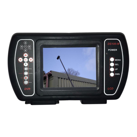
DART SYSTEMS MINI DARTEYE User manual

1
MINI DARTEYE –USER GUIDE
CONTENTS
Introduction
Mini DartEye Controls
Monitor Controls, Battery Meter
Light Operation, Sonde Operation
Distance Counter, Screen Titler
Wi-Fi
Wi-Fi App Note
Battery Charging/Recharging
Specifications
DS100 Initial Setup
DVR System Settings
Set Time Date menu
Manual Capture menu
Auto Capture menu
Motion Detect menu
Advanced Setting menu
Using the Display controls
Using the DVR Controls
Screen Icons
Keypad Controls
Still Image Capture
Manual Record and Playback
Charging the Batteries
Powering the system from AC adapter
Quick Tips
Specifications
Notes
2
3
6
6
7
8
9
10
11
12
14
17
18
20
21
21
22
23

2
MINI DARTEYE –USER GUIDE
INTRODUCTION
DartEye Mini Variants
Variant Part No Description
1 565-900 Mini DartEye 30 Mtr Standard Unit
2 565-901 Mini DartEye 30 Mtr Sonde & Meter Counter
3 565-902 Mini DartEye 30 Mtr Sonde, Meter Counter, Text
Editor & Wi-Fi
SAFETY WARNINGS
The system is not earthed. If mains operated equipment is connected to the system
then the external equipment must be earthed.
Do not use the Mini DartEye system in potentially explosive environments. This
equipment is not approved for use in hazardous environments.
Foul water can be a source of biological hazards. Wear appropriate protection at all
times.
The camera head will get hot during use, this is normal. Take care when handling
the camera at all times.

3
MINI DARTEYE –USER GUIDE
MINI DARTEYE CONTROLS
1. On / Off Switch
2. Monitor Controls
3. Recording Controls
4. Battery Charge Socket
5. 12v Adapter Socket
6. SD Card Slot
7. Battery Status Indictor
8. Light Control
9. Meter Counter Controls (Variant 2 & 3)
10. Video out Socket
11. Keyboard Socket (Variant 3) –Provides 10 pages of saveable text
plus shortcuts
12. 33Khz Sonde Switch (Variant 2 & 3) Switches Sonde off / on
13. Camera Connection Socket
2
3

4
MINI DARTEYE –USER GUIDE
13
5
4
1
6
9
8
7
12
Fig 2
Fig 1

5
MINI DARTEYE –USER GUIDE
11
10
Fig 3

6
MINI DARTEYE –USER GUIDE
MONITOR CONTROLS
Switch on
Turn the system on using the power
switch located at (fig 1 (1)).
The splash panel displays DartEye
Mini –No keyboard.
If version 3 unit then screen will
display DartEye Mini –keyboard
when turned on if the keyboard is
connected.
The total length of cable fitted to the
unit is displayed momentarily in the
bottom right of the screen.
Battery Meter
Check the battery level by pressing
and holding button (fig 2(7)) on the
Hub Control Panel, each
illuminated segment represents
20% battery life remaining.
Brake
Release the brake to allow the
camera and cable to be used by
lifting and turning the spring
plunger. To engage the brake turn
the spring plunger and the plunger
will drop into the next hole on the
reel hub.
Skids
The 50mm Skid provided with the
system is for use in pipes from
50mm to 100mm. The Camera can
be used without the skid fitted if
pipes under 50mm diameter are to
be inspected.
Monitor Removal
To remove the monitor from the
frame, loosen the two star knobs on
the reverse of the monitor and slide
the monitor up. The monitor can
then be used remotely. To store the
monitor in the transit case (optional)
unscrew the collar from the
connection cable and then pull to
release.
Connection is the reverse of this
operation.
When refitting the monitor to the
frame the cable should be routed
through the central slot in the
monitor mount plate.
LIGHT OPERATION
The Mini DartEye Camera head
has six high output LED’s. Use the
control knob on the Hub Control
Panel to vary the intensity of the
LED’s depending on working
conditions.

7
MINI DARTEYE –USER GUIDE
Sonde 33 KHz (Variant 2
& 3)
The unit is fitted with a high output
Sonde Transmitter which operates
at a frequency of 33KHz. The
Sonde is locatable by a standard
Camera / Cable locator with a
depth function.
To turn the Sonde on press the
Sonde Button (fig 2 (12)). A green
LED illuminates signifying that the
Sonde is working.
Due to the high output of the
transmitter the image is turned off
whilst the sonde is turned on, due
to interference caused by the high
signal strength.
DISTANCE COUNTER
(Variant 2 & 3)
The on screen distance counter
provides an estimate of how much
rod has been deployed, which can
be used to establish the position of
the camera head. The counter
should be calibrated before cable
deployment. The cable count can
be reset to zero at any time to give
a relative distance count, by
pressing F12.
Before each operation the system
should be calibrated with the
Camera Head in the Rod guide and
the entire rod stored in the reel and
pressing F11 on the keyboard.
When starting a survey the counter
can be zeroed by pressing F12.
Screen Titler Controls
(Variant 3)
NOTE –When the keyboard is
plugged in control of the meter
counter switches to the keyboard
from the Hub Plate. When the
keyboard is disconnected
control of the meter counter
switches back to the Hub Plate.
F1-F10 -Text Pages, loads a text
page, or toggles it off.
F11 -'CAL' function. Zero’s the
absolute count, and the relative
offset. It should only be used with
the entire rod on the reel.
F12 -'Zero' function. Updates the
distance offset so that the
displayed relative meterage will
read zero at this point.
Control-C -Clears the text display
and the current page from the
memory.
To move around the screen use the
arrow keys (up, down, left, right)
and the backspace / delete keys.
Control-M -Cycles meterage mode,
from metric, to imperial, to off, and
back to metric.
8
MINI DARTEYE –USER GUIDE
Control-D -Types the diameter
symbol.
Control-K -Types the degrees
symbol.
Control-E -Types the euro symbol.
Please ensure that the keyboard is
plugged in and disconnected whilst
camera is powered off. If the
keyboard isn’t functioning correctly
turn the camera off and back on
again.
Wi-Fi (Variant 3)
Go to the google play store or APP
store and search for “WIFIAV-
HD” and install the APP (see
logo for relevant APP) on the
device.
The icon should now appear on
your device.
Go to the Wi-Fi settings on your
device and select WIFIAV (Default
password: 12345678).
To view images remotely select the
APP on your device. Only one
device can be linked to the live view
at a time.
Controls
1 Press to record video, red
clock logo will appear in the
top left when view is being
recorded
2 Not Used
3 Press to save still image
4 Press to view recorded
video files
5 Press to view still images
6 Settings allows the
password to be changed
Zoom in and zoom out function can
be used if the mobile device allows.
1 2 3 4 5 6

9
MINI DARTEYE –USER GUIDE
Wi-Fi APP NOTE
The WIFI module in the DS100 is
by DEFAULT set for use with
iPhone SSID:WIFIAV (this is the
name of the WiFi connection as
seen on the mobile device).
If required the mode can be
changed to operate with any
ANDROID handset by following the
instructions below:
The DS100 monitor should be
powered on during this process.
On the back of the DS100 to the
right hand side of the product label
is a small hole. Using a pin, or
similar instrument, press the
internal switch 4 times to ENABLE
SSID:WIFIAV-SAMSUNG (this is
the name of the WiFi connection as
seen on the mobile device).
Check your mobile device to see
that WIFIAV-SAMSUNG is
available.
To return to iPhone press the
internal switch and hold for a
minimum of 10 secs.
Check your mobile device to see
that WIFIAV is available.
IT IS RECOMMENDED THAT THE
RESET HOLE BE COVERED
USING ONE OF THE LABELS
SUPPLIED TO PREVENT
MOISTURE AND DUST INGRESS.
Wifi reset switch

10
MINI DARTEYE –USER GUIDE
CHARGING THE
BATTERIES
N.B When the battery charger is
plugged in ensure the AC adapter
is NOT attached as damage to the
equipment may occur.
To Charge the System
Battery
The power switch on the Monitor
should be switched off, and the
charger three pin plug connected to
the socket on the underside of the
monitor (fig1(4)). The charger can
then be plugged into a suitable
mains outlet and switched on. The
charger will display a red LED until
fully charged then it will display
green.
Power Options
N.B When the AC adapter is
plugged in ensure that the battery
charger is NOT attached as
damage to the equipment may
occur.

11
MINI DARTEYE –USER GUIDE
INITIAL SET-UP
Connections
Connect short spiral cable (straight
connector) to the 4 pin socket
located on the back of the Display
Handset. Connect the second
connector of the spiral cable to the 4
pin socket on the Camera.
Insert SD card into Display
Handset and replace cover to
prevent water and dirt ingress.

12
MINI DARTEYE –USER GUIDE
DS100 OPERATING
FUNCTIONS

13
MINI DARTEYE –USER GUIDE
DVR SYSTEM SETTINGS
To Change the settings on each
screen:
Use the or to scroll up and
down the settings
Use the or to make change
to the settings
In each case, when complete,
press the ‘Settings’ button to
navigate to the next settings
screen, or ESC to go back to the
Preview screen where you can
create videos or take images.
CAM 1
SD
SETTINGS
Power-up the DS100 by switching it
on.
On power-up the ‘splash screen’
briefly appears followed by the
default screen.
Changing Default Settings
Press the ‘Settings’ button to access
the set-up screens. To navigate
through the screens, just press the
‘Settings’ button each time until
you’ve gone through all the setting
screens.

14
MINI DARTEYE –USER GUIDE
Channel 2 Video Settings: Screen 3
Frame Rate: 5/15/30 fps selectable.
The higher the frame rate, the bigger
the file memory.
File Save: Set to ‘No’.
Time Settings: Screen 1
Navigate and change the settings as per
the above instructions.
Channel 1 Video Settings: Screen 2
Frame Rate: 5/15/30 fps selectable.
The higher the frame rate, the bigger
the file memory.
File Save: Set to ‘Yes’ to save to SD
Card.
Record Settings: Screen 4
Quality: High/Middle/Low selectable - the
higher the quality the bigger the file
memory.
Overwrite: Overwrite automatically once
SD Card memory is full.
Section: 5/15/30/60 minutes for each
record file.
REC Mode:
Manual: Start/Stop recording manually.
Imotion: Start recording by motion detection.
Auto: Start recording by DVR on power-up.

15
MINI DARTEYE –USER GUIDE
SD Card Settings: Screen 5
Navigate and change the settings as per
the above instructions.
Size: Displays SD Card capacity.
Remain Size: SD Card memory available.
Remain File Num: Approx number of
recorded files left on SD Card. Format:
Format SD Card on recording.
System Settings: Screen 6
Navigate and change the settings as per
the above instructions.
Language: Select language.
Alarm Period: Set the alarm time frame,
set by motion detection. Time Stamp: Set
time and date to appear on video and
images. Reset: Reset to default settings.
Version: Software version number.

16
MINI DARTEYE –USER GUIDE
USING THE DISPLAY
CONTROLS
The display controls are on the
right hand side of the Display
Handset and are as follows:
a. To change PICTURE settings
press Menu once then Sel to select
either Bright, Contrast, Colour or
Language. Use Up/Down key to
adjust level or language.
b. To flip screen image
Press Menu twice then Up/Down
to select picture orientation.
N.B SYSTEM and CLOCK menus
are not currently utilized.

17
MINI DARTEYE –USER GUIDE
USING THE DVR SETTINGS
– VIDEO/STILL IMAGE
CAPTURE
Channel Settings
Whist in ‘Preview’ mode, select the
recording channel the camera is
connected to by pressing either of
the ‘CH 1/2 SEL’ (Channel Select)
buttons.
Still Image Capture
Whilst in ‘Preview’ mode, to
capture a static image press the
‘Image’ capture button.
Still Image Viewing
Whilst in ‘Preview’ mode, to view
static image files, first access and
view the folder on the SD Card by
pressing the ‘Folder’ button.
Use the or to scroll up and
down if there is more than one
folder.
Press the ‘SEL’ (select) button to
select the folder and to view the
files within the folder.
Use the or to scroll up and
down through the files.
CH 1/2 SEL
CH 1/2SEL
REC
SEL

18
MINI DARTEYE –USER GUIDE
To delete files and folders press
the ‘Folder’ button twice.
Press the ‘SEL’ button to select the
file and to view the image.
Manual Record Video
Whilst in ‘Preview’ mode, to record
video press the ‘REC’ (record)
button.
To stop recording press the ‘STOP’
button.
Viewing Recorded Video
Whilst in ‘Preview’ mode, to view
record video files, first access and
view the folder on the SD Card by
pressing the ‘Folder’ button.
Use the or to scroll up and
down if there is more than one
folder.
Press the ‘SEL’ button to select the
file and to view the image.
Use the or to scroll up and
down through the files.
REC
SEL
REC
SEL
REC
SEL

19
MINI DARTEYE –USER GUIDE
To delete files and folders press
the ‘Folder’ button twice.
Press the ‘SEL’ button to select the
file and to view the video.
To play video press ‘PLAY’ button.
Use this button to also ‘PAUSE’
video.
To ‘FAST FORWARD’ or
‘REWIND’ use or .
CHARGING THE
BATTERIES
N.B. When charging the batteries
ensure that the AC adapter is
NOT plugged in, damage to the
equipment may occur.
The internal and auxiliary external
battery are charged by the same
charger supplied with the system.
To Charge the Internal
Battery
The power switch on the Handset
should be switched off, and the
charger 3 pin plug connected to the
socket on the underside of the
Handset. The charger can then be
plugged into a suitable mains outlet
and switched on. The charger will
display a Red LED until fully
charged then it will display Green.
To Charge the Internal
Button Battery
The power switch on the Handset
should be switched off, and the
charger 3 pin plug connected to the
charging socket on the underside
of the Handset. The charger can
then be plugged into a suitable
mains outlet and switched on. Turn
the DS100 Handset on and charge
for 6 hours. After 6 hours turn the
DS100 Handset off and remove the
charger. The internal Button
Battery which runs the internal
clock is now fully charged.
THIS MUST BE DONE ONCE A
MONTH.
REC
SEL
FOLDERS/PLAY/PAUSE/DEL
Table of contents
Other DART SYSTEMS Analytical Instrument manuals