Metrohm 845 Eluent Synthesizer User manual

845 Eluent Synthesizer
Handbuch
8.845.8001EN


Metrohm AG
CH-9100 Herisau
Switzerland
Phone +41 71 353 85 85
Fax +41 71 353 89 01
www.metrohm.com
845 Eluent Synthesizer
Handbuch
8.845.8001EN 08.2008 zst

Teachware
Metrohm AG
CH-9100 Herisau
This documentation is protected by copyright. All rights reserved.
Although all the information given in this documentation has been
checked with great care, errors cannot be entirely excluded. Should you
notice any mistakes please send us your comments using the address
given above.
Documentation in additional languages can be found on
http://documents.metrohm.com.

Contents
845 Eluent Synthesizer / Instructions for Use 8.845.8001EM
I
Table of contents
1Introduction.................................................... 1
1.1 Instrument description ............................................................. 1
1.2 Parts and controls .................................................................... 1
1.2.1 Front of 2.845.0010 .......................................................................2
1.2.2 Front of 2.845.0020 .......................................................................3
1.2.3 Rear view .......................................................................................4
1.3 Information on the Instructions for Use .................................. 6
1.3.1 Organization ..................................................................................6
1.3.2 Notation and pictograms ..............................................................7
1.4 Safety information..................................................................... 8
1.4.1 Electrical safety..............................................................................8
1.4.2 General precautionary rules ..........................................................8
2Installation ..................................................... 9
2.1 Setting up the instrument ......................................................... 9
2.1.1 Packaging......................................................................................9
2.1.2 Check.............................................................................................9
2.1.3 Location .........................................................................................9
2.2 Mains connection...................................................................... 9
2.3 Connection to PC.................................................................... 10
2.4 Dosino(s)/Stirrer connections................................................ 11
2.5 Tubing connections ................................................................ 11
2.5.1 Instrument with tubing connections ............................................12
2.5.2 Connecting the drainage tubing .................................................13
2.5.3 Connections to bottle adapter ....................................................13
2.5.4 Connecting the components.......................................................13
2.6 pH Controller........................................................................... 14
2.6.1 Tubing connection for pH Controller...........................................14
2.6.2 pH Controller cable connection ..................................................15
3«Mix Control» software................................. 16
3.1 Introduction to the software ................................................... 16
3.1.1 The principle of «Mix Control» .....................................................16
3.1.2 Procedure after the first start of «Mix Control» ............................16
3.2 Main Window........................................................................... 16
3.2.1 Menus..........................................................................................16
3.2.2 Description of the symbols .........................................................19
3.3 Method..................................................................................... 20
3.3.1 General information about methods ...........................................20
3.3.2 Parameters ..................................................................................20
3.3.3 pH Adjustment.............................................................................21
3.3.4 Creating a method.......................................................................23
3.4 Configuration .......................................................................... 23
3.4.1 Depot ...........................................................................................23
3.4.2 Components................................................................................25
3.4.3 System Settings...........................................................................26
3.4.4 Report Configuration ...................................................................27
3.4.5 User Administration .....................................................................29
3.4.6 Rinse............................................................................................33
3.5 Extras....................................................................................... 36
3.5.1 Sign methods ..............................................................................36

Contents
845 Eluent Synthesizer / Instructions for Use 8.845.8001EN
II
3.5.2 Audit trail...................................................................................... 37
3.5.3 Window "Report List" ................................................................... 39
3.5.4 GLP Manager .............................................................................. 41
3.5.5 Firmware Update......................................................................... 43
3.5.6 Login Service............................................................................... 44
4Maintenance - Troubleshooting...................45
4.1 Care ......................................................................................... 45
4.1.1 Decommissioning ....................................................................... 45
4.2 Dosing units ............................................................................ 45
4.2.1 Deinstallation............................................................................... 45
4.2.2 Cleaning ...................................................................................... 46
4.2.3 Installation ................................................................................... 47
4.3 Troubleshooting...................................................................... 49
5Annex ............................................................ 50
5.1 Technical data......................................................................... 50
5.1.1 Interfaces..................................................................................... 50
5.1.2 Mains connection........................................................................ 50
5.1.3 Safety specifications ................................................................... 50
5.1.4 Electromagnetic compatibility (EMC) ......................................... 50
5.1.5 Ambient temperature .................................................................. 51
5.1.6 Dosing drive ................................................................................ 51
5.1.7 Dosing Unit.................................................................................. 51
5.1.8 Reference conditions .................................................................. 51
5.1.9 Dimensions ................................................................................. 51
5.2 Standard equipment ............................................................... 52
5.2.1 Standard equipment for 2.845.0010........................................... 52
5.2.2 Standard equipment for 2.845.0020........................................... 54
5.2.3 Accessories for pH adjustment (optional) .................................. 57
5.2.4 Optional accessories .................................................................. 61
5.2.5 Producers of concentrates and standards ................................. 62
5.2.6 Systems for producing ultra pure water ..................................... 62
5.3 Warranty .................................................................................. 63
5.3.1 Warranty ...................................................................................... 63
5.3.2 Declaration of Conformity ........................................................... 64
5.3.3 Quality Management Principles .................................................. 65
5.3.4 Index............................................................................................ 66
List of figures
Figure 1: Front of 2.845.0010 ....................................................................... 2
Figure 2: Front of 2.845.0020 ....................................................................... 3
Figure 3: Rear view of 845 Eluent Synthesizer ............................................. 4
Figure 4: Tubing connections..................................................................... 12
Figure 5: Dosing unit attachment ............................................................... 46
Figure 6: Connections with one Dosino ..................................................... 47
Figure 7: Connections with two Dosinos.................................................... 48
1.1 Instrumentdescription
845 Eluent Synthesizer / Instructions for Use 8.845. 8001EN
1
1 Introduction
The 845 Eluent Synthesizer and its associated «Mix Control» soft-
ware can be used for the fully automatic preparation of solutions and
mixtures such as eluents, mobile phases, buffer solutions or standards
with the required concentration and component ratios.
The 845 Eluent Synthesizer is based on the Dosino technology which
allows high-precision dosing to be carried out. Both aqueous (acidic or
basic) and organic mixtures can be prepared. The system (with an op-
tional extension) can also be used to adjust the pH.
1.1 Instrument description
Two versions of the instrument are available :
• 2.845.0010 845 Eluent Synthesizer with one Dosino
• 2.845.0020 845 Eluent Synthesizer with two Dosinos
The 2.845.0010 Eluent Synthesizer with one Dosino can be used to mix
together three components (of which one is the main component).
The 2.845.0020 Eluent Synthesizer with two Dosinos can be used to
mix together five components (of which one is the main component).
Both versions contain a built-in magnetic stirrer The software «Mix Con-
trol» is supplied with the instrument.
The 2.702.0120 Eluent Synthesizer Package for the automatic pH ad-
justment is offered as an option. In addition to a 702 Titrino this also
contains an Aquatrode, a 10 mL exchange unit and a Remote Box (see
Section 5.2.3).
The 845 Eluent Synthesizer is connected to a PC via a USB and ope-
rated with the «Mix Control» PC software provided. The operation of the
software is described in the online help and in Section 3of these In-
structions for Use.
1.2 Parts and controls
In this Section you will find the numbers and designations of the parts
and controls of the 845 Eluent Synthesizer. The numbering applies
throughout the Instructions for Use, i.e. bold numbers in the text (e.g.
3
) refer to the parts and controls illustrated here.
1 Introduction
845 Eluent Synthesizer / Instructions for Use 8.845. 8001EN
2
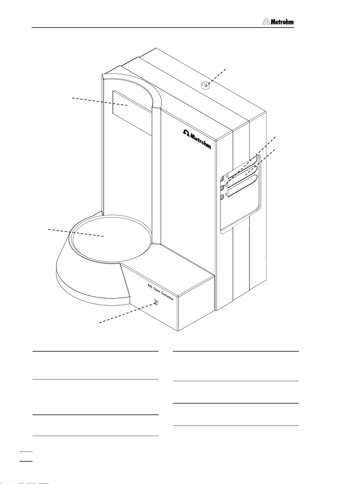
1.2.1 Front of 2.845.0010
Figure 1: Front of 2.845.0010
1LED "Power"
Lights up green when the instrument is
switched on.
2Place for eluent bottle
To place the eluent bottle while pre-
paring the mixture. There is a built-in
magnetic stirrer beneath it.
3Holder for bottle adapter
Holder for bottle adapter 21.
4Dosino 1 outlet
Outlet for the components from Dosino
1.
5Connections for components
Connections for components 1 - 3.
6Recesses for magnetic labels
For identifying components 1 - 3.
2
3
6
1
4
5

1.2 Partsandcontrols
845 Eluent Synthesizer / Instructions for Use 8.845. 8001EN
3
1.2.2 Front of 2.845.0020
Figure 2: Front of 2.845.0020
1LED "Power"
Lights up green when the instrument is
switched on.
2Place for eluent bottle
The eluent bottle is placed here for
preparing the mixture. There is a built-
in magnetic stirrer beneath it.
3Holder for bottle adapter
Holder for bottle adapter 21.
4Dosino 1 outlet
Outlet for the components from Dosino
1.
5Connections for components
Connections for components 1 - 5.
6Recesses for magnetic labels
For identifying components 1 - 5.
7Dosino 2 outlet
Outlet for components from Dosino 2.
1
2
7
4
5
6
3

1 Introduction
845 Eluent Synthesizer / Instructions for Use 8.845. 8001EN
4
1.2.3 Rear view
Figure 3: Rear view of 845 Eluent Synthesizer
8Lead-throughs for Dosino cables
9Lead-through for stirrer cable
10 Connection "Stirrer / MSB3"
For connecting a stirrer (cable marked
with "Stirrer").
11 USB-connections USB1 and USB2
USB-ports (type A) for connecting de-
vices with a USB cable.
12 Controller connection
For connecting to a PC.
11
12
10
13
14 15
16
9
8 18
17
19

1.2 Partsandcontrols
845 Eluent Synthesizer / Instructions for Use 8.845. 8001EN
5
13 Connection "MSB1 / Dosino 1"
For connecting Dosino 1 (cable
marked with "Dosino 1").
14 Connection "MSB2 / Dosino 2"
For connecting Dosino 2 (cable
marked with "Dosino 2") (only for ver-
sion 2.845.0020).
15 Connection "Remote Box / MSB4"
For connecting the Remote-Box for pH
adjustment with Titrino(s) (see Section
2.6.2).
16 Mains connection socket
Mains connection (see Section 2.2).
17 Device type and serial number
18 Connection for drainage tubing
For draining off any liquid that has es-
caped inside the instrument (see Sec-
tion 2.5.2).
19 Rear panel

1 Introduction
845 Eluent Synthesizer / Instructions for Use 8.845. 8001EN
6
1.3 Information on the Instructions for Use
Please read through these Instructions for Use carefully before you put
the 845 Eluent Synthesizer into operation. The Instructions for Use
contain information and warnings to which the user must pay attention
in order to assure safe operation of the instrument.
1.3.1 Organization
These Instructions for Use 8.845.1003 for the 845 Eluent Synthesizer
provide a comprehensive overview of installation, operation, mainte-
nance, fault rectification and technical specifications of this instrument.
The Instructions for Use are organized as follows:
Sect. 1 Introduction
General description of instrument, parts and controls
and safety notes.
Sect. 2 Installation
Installation of the instrument, mains connection, con-
nection to PC, connection of Dosino(s)/stirrer, pH
controller.
Sect. 3 «Mix Control» software
Explanation of how to use the «Mix Control» software.
Sect. 4 Maintenance - Troubleshooting
Care, cleaning the dosing units, troubleshooting.
Sect. 5 Annex
Technical data, standard equipment, options, war-
ranty, conformity declarations, index.
To find the required information on the instruments, use either the Ta-
ble of contents or the Index at the back.

1.3 InformationontheInstructionsforUse
845 Eluent Synthesizer / Instructions for Use 8.845. 8001EN
7
1.3.2 Notation and pictograms
The following notations and pictograms (symbols) are used in these In-
structions for Use:
12 Part or control
Hazard
This symbol draws attention to a
possible danger to life or of injury if
the associated directions are not
followed correctly.
Warning
This symbol draws attention to
possible damage to instruments or
instrument parts if the associated
directions are not followed cor-
rectly.
Caution
This symbol marks important in-
formation. First read the associated
directions before you continue.
Comment
This symbol marks additional in-
formation and tips.
1 Introduction
845 Eluent Synthesizer / Instructions for Use 8.845. 8001EN
8
1.4 Safety information
This instrument must only be operated in accordance with the infor-
mation provided in these Instructions for Use.
1.4.1 Electrical safety
While electrical safety in the handling of the 845 Eluent Synthesizer is
assured in the context of the specifications EN / IEC 61010-1, the fol-
lowing points should be noted:
• Electronic parts
Only qualified Metrohm technicians should carry out service work on
electronic components.
• Protection against electrostatic charges
Electronic components are sensitive to electrostatic charges and can
be destroyed by a discharge.
1.4.2 General precautionary rules
• Handling of solvents
Check all lines of the IC system periodically for possible leaks. Follow
the relevant instructions regarding the handling of flammable and/or
toxic solvents and their disposal.

2.1 Settinguptheinstrument
845 Eluent Synthesizer / Instructions for Use 8.845. 8001EN
9
2 Installation
2.1 Setting up the instrument
2.1.1 Packaging
The 845 Eluent Synthesizer is supplied together with the separately
packed accessories in special packagings containing shock-absorbing
foam linings designed to provide excellent protection. Please store all
these special packagings as only they assure transport of the
instrument free from damage.
2.1.2 Check
After receipt, immediately check whether the shipment is complete and
has arrived without damage (compare with delivery note and list of
accessories in Section 5.2). In the case of transport damage, see in-
structions in Section 5.3.1 "Warranty".
2.1.3 Location
This instrument was developed for internal laboratory use; it should not
be used in explosion-endangered locations.
Place the instrument on a suitable vibration-free laboratory bench, pro-
tected as much as possible from corrosive atmospheres and contact
with chemicals. Choose a location where the temperature is usually be-
tween +5°C and +45°C. The instrument should be protected against
excessive variations in temperature and direct sunlight.
2.2 Mains connection
Mains cable
The instrument is supplied with one of three mains cables
• 6.2122.020 with plug SEV 12 (Switzerland, …)
• 6.2122.040 with plug CEE(7), VII (Germany, …)
• 6.2122.070 with plug NEMA 5-15 (USA, …)
which are three-cored and fitted with a plug with a grounding pin. If a
different plug has to be fitted, the yellow/green lead (IEC standard)
must be connected to protective ground (protection class 1).
Any break in the grounding inside or outside the instrument can make
it a hazard!
Mains connection
Plug the mains cable into mains connection plug 16 of the 845 Eluent
Synthesizer.

2 Installation
845 Eluent Synthesizer / Instructions for Use 8.845. 8001EN
10
2.3 Connection to PC
The 845 Eluent Synthesizer is controlled by the «Mix Control» PC soft-
ware (see Section 3).
System requirements
• Processor: Pentium III
• Main memory: 256 MB RAM
• Free memory space: 100 MB for program files
• CD-ROM drive
• Connection: one free USB slot (type A)
Microsoft WindowsTM 2000 or WindowsTM XP or WindowsTM Vista
must be used as the operating system.
Installation
To connect the instrument and install the software proceed as follows:
1 Installing the «Mix Control» program
• Insert installation CD in CD disk drive.
• If autostart has not
been activated for the CD drive: select
<Start> and Run. Search for the Setup.exe file on the in-
stallation CD and click on <OK>.
• Click on "Mix Control" and follow the instructions of the
setup program.
2 Connection 845 - PC
• Connect the 845 Eluent Synthesizer (socket "Controller" 12)
to a USB connection
(type A) of your computer with the
6.2151.000 Cable (see the instruction manual for your
computer).
• A system test will automatically be carried out on the 845
Eluent Synthesizer.
• The LED "Power" 1lights up when the system test has been
completed and the instrument is ready for use.
The plug for connection of the 845 Eluent Synthesizer is fitted with a
"pull-out protection device" which prevents the cable from being
pulled out accidentally. When you wish to insert or remove the plug
you must first pull back the outer plug sleeves (marked with arrows).
You can extend the connection with a commercially available USB ex-
tension cable (type A/m – type A/f). The length of the connection
should not exceed 5 m. If you require a longer connection then you
must use a USB signal amplifier. Up to five USB signal amplifiers can
be connected in series; this allows a maximum extension of 25 m.

2.4 Dosino(s)/Stirrerconnections
845 Eluent Synthesizer / Instructions for Use 8.845. 8001EN
11
3 Start the «Mix Control» program
• Double click on the icon of the «Mix Control» software.
• The device is recognized automatically.
2.4 Dosino(s)/Stirrer connections
Dosino(s) and stirrer are part of the instrument. The instrument is supp-
lied with them already connected up; these connections should not be
altered.
Correct connection:
Cable markings Connection markings
Dosino 1 MSB1
Dosino 1
Dosino 2 MSB2
Dosino 2
Stirrer Stirrer
MSB3
2.5 Tubing connections
The drainage tubing (Section 2.5.2) and the component inlets and out-
lets (Sections 2.5.3/2.5.4) must be connected.
2 Installation
845 Eluent Synthesizer / Instructions for Use 8.845. 8001EN
12
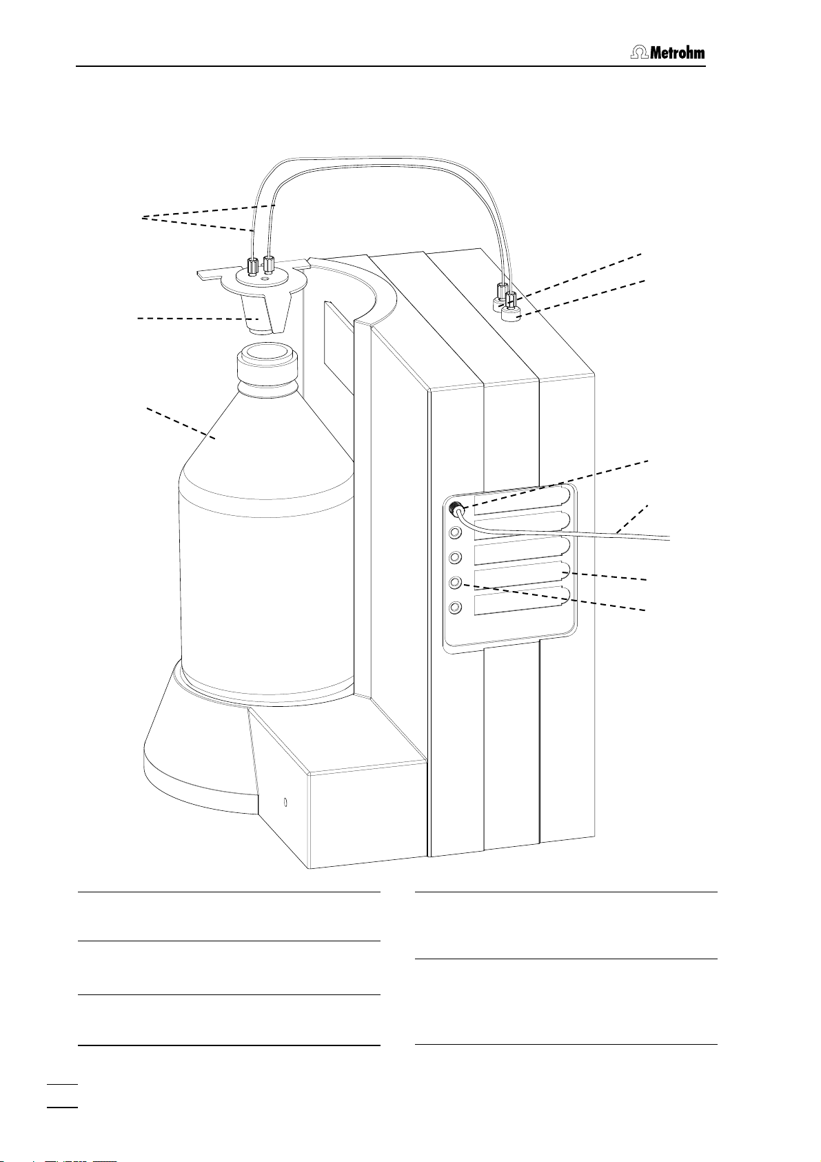
2.5.1 Instrument with tubing connections
Figure 4: Tubing connections
4Dosino 1 outlet
Outlet for components from Dosino 1.
5Connections for components
Connections for components 1 - 5.
6Recesses for magnetic labels
For identifying components 1 - 5.
7Dosino 2 outlet
Outlet for components from Dosino 2
(only for version 2.845.0020).
20 FEP tubing connection
6.1838.000 Tubing connections for
connecting "Dosino 1 outlet" 4/ "Dos-
ino 2" outlet 7to the bottle adapter 21.
22
21
20
7
23
24
5
6
4

2.5 Tubingconnections
845 Eluent Synthesizer / Instructions for Use 8.845. 8001EN
13
21 Bottle adapter
6.1602.180 Bottle adapter as connec-
tion piece between eluent bottle 22
and tubing connection 20.
22 Eluent bottle
6.1608.070 Clear glass bottle for the
mixed eluent.
23 Pressure screw
6.2744.170 Pressure screw for con-
necting component capillary 24 to
component connection 5.
24 PTFE capillary
6.1803.130 Capillary for connecting the
components.
2.5.2 Connecting the drainage tubing
Connect 6.1816.020 Silicone tubing to connection 18 on the rear panel
of the 845 Eluent Synthesizer and place the other end in a waste bottle.
2.5.3 Connections to bottle adapter
The tubing should not dip into the produced mixture. Make sure that
the FEP- Tubing Connection 6.1838.000
20
does not loom too deep
into the bottle.
2.845.0010:
Connect 6.1838.000 FEP Tubing connection 20 to the 6.1602.180 21
Bottle adapter and to Dosino outlet 4. Then, attach the Bottle adapter to
the Eluent bottle 6.1608.070.
2.845.0020:
Connect two 6.1838.000 FEP Tubing connections 20 to the 6.1602.180
21 Bottle adapter and to Dosino outlets 4and 7. Then, attach the Bottle
adapter to the Eluent bottle 6.1608.070.
2.5.4 Connecting the components
The main component (e.g. water) must be connected to the com-
ponent connection with the number 1 (see Section 3.4.2). The main
component is used (at the end of the mixing process) to make the
volume up to the total volume given in the method (see Section
3.3).
Proceed as follows to connect the various components:
1 Connect capillary to 845
Connect 6.1803.130 PTFE capillary 24
with 6.2744.170 Pressure
screw 23 to component connection 5.

2 Installation
845 Eluent Synthesizer / Instructions for Use 8.845. 8001EN
14
2 Connect capillary to the components
Components from a bottle:
• Insert 6.1803.130 PTFE tubing 24 through the bottle attach-
ment into the component bottle (e.g. the combination
6.1602.160 bottle attachment GL 45 and 6.1608.030 bottle;
see Optional accessories section 5.2.4).
Components from an MPak (from Chata Biosystems, see section
5.2.5):
• Push the 6.1808.200 MPak coupling onto 6.1803.130 PTFE
tubing 24
by loosening the screw cap from the coupling
and pushing the smaller opening over the tubing. Then
screw the coupling into the cap:
• Click the 6.1808.200 MPak coupling onto the lower outlet of
the MPak.
2.6 pH Controller
The pH of the prepared mixture can, if necessary, be adjusted auto-
matically by using the (optional) extension kit. If the pH is to be adjusted
from one side then one pH Controller is required, adjustment from both
sides (without changing the titrant solution) requires two pH Controllers.
We recommend the use of 702 Titrinos as pH Controllers (for supply
package see Section 5.2.3). Other Titrinos can also be used (supply
package for required accessories see Section 5.2.3).
2.6.1 Tubing connection for pH Controller
If the pH is to be adjusted automatically after the mixing process then
adaptations are required to the tubing connections to the 845 Eluent
Synthesizer.
1 Replace bottle adapter 21
6.1602.180 Bottle adapter 21
must be replaced by 6.1602.190
Eluent bottle head.
• Screw off the 6.1838.000 FEP tubing connection(s) 20 from
6.1602.180 Bottle adapter 21.
• Screw the 6.1838.000 FEP tubing connection(s) 20 to M6
thread(s) of 6.1602.190 Eluent bottle head.
This manual suits for next models
2
Table of contents
Other Metrohm Analytical Instrument manuals

Popular Analytical Instrument manuals by other brands


Sutter Instrument
Sutter Instrument Lambda 721 Operation manual

P&E Microcomputer Systems
P&E Microcomputer Systems USB Multilink ACP Technical summary

Bosch
Bosch GLM 50 C Professional Original instructions

flexbar
flexbar 13290 user manual

Holex
Holex 49 2928_2000 instruction manual

RND
RND 355-00004 user manual


