Allied Radio KNIGHT VTVM User manual

THEKNIGHT
vTvi
AtLI
ED
RADIO
IOO N. WESTERN AVE.. CHTCAGO SO, tLL. HAYMARK€T t-6eoo

HOWTOREADCOI.OR
(ODT
OlIRTSISIORS
A}IDCOIIDE}ISTRS
All carbon resistorsare produced and color<od.d under standardsset by ihe RTMA {Radio and TelevisionManu-
facturers'Association).Undcr thesestandardsthe useris assurd of a wide rangc of valu€s
atrd of a univenal color-
coding systemthat permits casy idrntification of any carbon r*tor. To detemine the value of a resistor,hold it
with the colorcd bandsreadinefron the left end. as illustrated.and refer to the chart.
BANDA BANDB BANDC IAND D
Color Color Color
Eloct
Gr.y
0
I
2
3
5
6
7
9
slock
R.d
8lu.
0
I
2
3
1
5
6
7
I
9
Blo.t
R.d
Bluc
Gold
Silv.r
0
xt0
xl00
xt.000
xt0,000
xr00,000
X |0Million
- r0
_ t00
Silv.r ):20%
+ t0%
Thc first band (A) shows
the firlt 6gure of the resistor
value, the secondband (B) showsth€ second6gure,the thi.d
band (C) iDdicatcsthe number of zerosto add. The fourth band (D), which js not included on all resiston,mrrely
indicatcstolcran.c: silver for a (plus or minus) l0%, gold fot t 5%. lf the (D) band is omitted, thc tol.ran(c
n :! 20/..
Hereisanexamplc:BandA yellow,
bandB violet,
bandC yellow,
bandD silver: (4) (7) (X10,000)(110%)
or 470,000
ohms,i l0% tolerance.
Mica condrnsen arc frequently color-.oded. The colored dots havethc sane figure meaning asfor resistors
(that is,
black is 0, brown is l, elc.) but the.e are three systemsfor reading thc complete values.
OLD RMA SIX
DOTSYSTEM RTMA
PROPOSED
ANDJAN-C-5
THREE
DOT SYSTEM
tr
ooo
ooo
ooo
ooo
Enti,eConrenhCoptrighr6d 1956,
b),ALIIEDiADIO CORP, p'i{sd ii U.S,A.

SPECIFICATIONS
DC
Ranses-.........-...-.....-..-.-.C€nter
scaleat 10 with
multiptiersXl,Xl0,
x 100,x 1000,
x 10K,
X 100K,X 1Mes.
PrintedCirGuill
Tube Complemenl:
Bortery:
Ranaes............-...... .... 1.5,
5, 15,50, 150,
500,
and 1500volts full scale.
Input Resistance ..........11Megohms (1 Megohm
in probe) on all ranges.
Circr1it....-...-..... ... Push -Pull batanced
bridge with 12AU7 t\rin
triode.
Accuracy ..... ... 13% full scale.
RMS Ran9es..................-1.5, 5, 15, 50, 150, 500,
1500 volts full scale.
Accuracy.............-.............15t;futl scale,
Peak-to-PeakRanges.....4,14,40,140,400,1400,
4000 volts.
4Y." 200aA mov€m€nt.
1% pr€cision
type.
Copperetchedotr lami
12AU7,
twin triode me-
6AL5, twin diode fuu
105-125volts,50-60cy-
clesAC.
1.5
volt "C" battery.
voltage, rcsistance,and AC voltage after rectification
by the fullwave rectifier. \
The meter employed
is an €xtremely stable,sensitive
200 microampere movement. The muttipliers are 1%
precision
type. Overall accuracjr
of tl1eDC functions is
13% of full scalereadins, and :!5% on AC functions.
A wide choice
of measurements
is provided arvDa you
seven ranses on DC, AC, and resistance. Bot}l RMS
and peak-to-peakAC voltages may b€ measurcd.
Your KNIGHT VTVM, through the useof the print-
cd circuit. saves
a greal d"at of t,dious wiring, as;ures
you ot a finisl'ed,nstrument
which compsres
closety
lo rhe original ensinFerina
modet,
ana irov:aes yoir
wrth an instl.ment \ orlh manv limes
irs low cost.
Before startina to build your KNIGHT VTVM,
check each palt against the Palts List on page 23. If
you are unableto identify someof the parts by sight,
locate them on the pictorial diagrams. Capacitor and
r€sistor values,if not printed on the part, canbe found
with the aid of the color codechat.
Hardware is listed in the last part of the parts List.
To keep our kits at the lowest possiblepdce, we frc,
quently weigh hardware raiher than to count it.
Therefore, do not be concerned if more nuts anar
machine screws, for example, are supplied than are
specified in the Parts List.
The only tools required for buildins your KNIGHT
VTVM are: Long-nosepliels, diasoral cutters, screw-
driver,
sei-scrF$d.ivcr. rnd a 50-wa||soldering
iron.
You may want to use a larger iron for soldedna the
contacts other than the pdnted circuit, but DO NOT
USE AN IRON LARGER THAN 50 WATTS FOR
MAKING THE SOLDER CONNECTIONS ON TIIE
PRINTED CIRCUIT. A good set of tools is listed at
t]le erd of tlje Parts List.
Study the pictorial diasrams and notehow the palts
are mounted.These
pictorial diagrams showthe actuat
location of all parts and wirirs. The schematic dia-
gram shows how the parts are cormect€d electrica.lly
aDd is helpful in understanding how Urc circuitg work.
The step-by-Etepinstructions wer€ prepaled by a
skilled techDicianwhite he was actually building the
KNIGHT VTVM. Therefore, they are the best and
fastest way of assembling this instrum€nt. We suggest
that you read throuah the instructions b€fore building
the VTVM. This will €nable you to Jamiliarize yourseu
with the proc€du.e and avoid possible erroru. We
invite you to use the blank parentheses,( ), beforc
eachstep to check it off ajter you have completedit.
Each step is clearly illustraLedon an accompanying
line drawing. Somebuilders prefer to "cross out" each
wire and component on the drawings with a colored
pencil after it is instaUed.While an excellent way to
avoid mistakes, atrd hiAhly recommendedby us, this
procedure .esults in drawinAs that are difficult to re-
use.Fo! this reasor eachwiring view is reproducedon
a sepamte,folded sheetof paper.
You arenowreadyto build your KNIGHT VTVM.
AC
HOW TO BUITDTHE
KNIGHT
VTVM
Your KNIGHT VTVM usesa p nted circuit which
assuresyou that the VTVM will be an accurate, reti
abletest instrument regardlessof age.A sheetof cop-
per is bondedto a sheet of phenolic.When the wiring
pattern has been determined, the unused portion of
the coppe. sh€et is etched off leaviDgan exact dupli-
cation of the enginee ng prototype. Exact duplication
is one of the Areatest advantages of pdnted circuits,
and pr€vents variation in wiring aDd performance
from instrument to instrument.
Your KNIGHT VTVM is ait eiectronic. That is, the
bridge ci.cuit is used for every measurement of DC

PIII JACX OETAIL
10K
t(-za
OHMS
ADJ
10K
ZERO
ADJ
5@,,o
<b-s
FIGUREI. MOUNTING
THEPARTS
ON TflEPANEI.

MOUNTINGTHE
Before you begin mounting t]le parts, place a pad
or a soft cloth on your work table to protect the finish
on the front panel.
SEEFIGURESI AND 2
( ) Insert the Ehort flat head screw throush the hole
in the top center of the panel. Placean extenal
iockwasher over the screw. Next put one of the
cable clampsove. the screw. Now, put on an in'
temal lockwasher and tighten a nut over it very
securely. SeeFiFrre 2.
S *ut
rnr€RflaL
Locxw
sHaR
@CABINET
MOUNIING
CLIP
<-€>i1{cAB.E cLAMp)
YFJ
I
ETTERNAL
LOCT*ASHER
€D
I
$..o, ".o0."".*
FIGURE2. HOWTOASSEI,ISLETHECABINETCLAMP
( ) MountR-25,
10KohmsOHMSADJUSTpotenti-
omete.,
in thelalAe
hole
in theleft centerof the
paDel.Use two nuts to hoDnt this coDtlol as
showtrin Eigure3.
PARTs
ON THEPANEI"
( ) Mount J-3, the black pin jack, ir the lower right
corner of the parcl in the
( ) Mount J-2, the chassis connecto. in tte lart€
hole in the lower center of the panel. This con-
nector is supplied with a shoulderedfiber wash-
er. Take this vasher off and throw it away.
Place the flat fib€r washer over the sma-ll
threaded end of the conn€ctor. Scnpe the paint
from around this hol€ on the .ear of the parcl.
Insert the small thr€aded end t}lloush the hole
in the panel. Place the solder lua and the flat
metal washer on the connector and tiahten the
rut securely. SeeFigure 4.
WIRINGAND SOLDERING
HINIS
How well a pieceof electronic equipm€nt works of-
t€n deperdson the quality of workmanship usedin it!
construction. It is for this reason that the following
sugge6tions
are made. Thesehints are mainly for the
besinDer, however, even experienced persons mav
beDefit from a brief review.
5
FIGURE4. HOW TO MOUNTTHE
CHASSISCONNECTOR
( ) Mount S-1,the lons triple wafer RANGE switch
i! the hole in the lower left corner of the panet.
The long contact on the endwsfer must be posi-
tioned as shown in Figure 1. Th€ blank spaceon
the wafer near the shaft end must be toward
J-1. Use a larse nut and a lockwasher on tbe
inside of the panel. Fasten it securely witb
another la.ge nut. Place a large knob on th€
shaft. Be sure the line on the knob lines up ex-
actty with the printed dots on the panel. ff not,
rotate S-1so the scaleon the panel and the lir€
otr the knob cor?*pond.
( ) Mouni S-2, the other tdpie waler FUNCIION
switch, in the other hole on the riaht of the
panel. Us€another large nut and Iockwasher ir-
sidet}Ie panel. Usea large nut outside the pan€1.
Again place
a knob on the shaft alld be Bure
that
the line on the knob lines up with the scale on
You hav€ finished mounting the parts oD the pan€I
until aft€r the switches are wired.
/zcoNrRoL
FIGURE3. HOW TO MOUNTA CONTROL
( ) Mount R-27, 10K ohm ZERO ADJUST potenti-
ometer, in the large hole in the right center of
the panel, in the same manner.
( ) Mount the pilot liAht socket betveen R-25 and
R-27. The bracket must be lositioned as shown
in Figure 1.
( ) Mount J-1, the red pin jack, in the lower left
corner of t]1e panel. Use a shoutilered liber
washer on the inside oI the panel to insulate the
jack f.om the panel. Now, tighten a nut against
the washer- Refer to the pin jack detail in the
upper left comer of Figure 1.
FRONT
PANEL

The insulated wire furnish€d wit}1this kit is cut to
lensth and th€ ends are st pped. Each different col-
ored wire is a different lensth, ther€fore, be sure to
usethe color specifiedin eachof the wiring steps
A lotrg piece
of bare wire is inctuded.
whenever it is
necessa.y to use some of it, the exact letrgth of the
pi€cer€quir€d is given.
The flexible tubing Eupplied is called "spash€tu".
SpaAhetti 's us€d to cover the bare end leads of some
of the components and portions of some of tbe bare
wi.es when there is danger they will touch oth€r bare
wires or the chassis.
The proper way to conn€cta wire or lead to a solder
terminal is shown in Figure 5. To insure a good me-
chanical connection,
squeeze
the wire agarnst tbe ter-
minal wit]l your long nose pliers after it has been
hook€d on. Make sure the wires, leads, and terminals
are cleanbefore connectins them. If necessarv,
s€rape
them witli a pocket knife until any foreiAn substance,
such as wax, is removed.Be extremely careful not to
nick the wirc with the knife, or it may brcak wh€D it
B€foresoldelinA,thetip of yoursolderingironmust
beprop€rlytinned.To do this, cleanthe surfaces
of
the tip with Bteelwool,or a fine file, until the bright
copp€rsurface is exposed.Plug the iron in ard allow
it to heat until it melts solder. Apply solder to the tip
until it is weu cove.ed with a thiD coat. Wipe off the
excess solder with a ra8. The tip should now be
"shiny". Re-tintle tip whenever
it becom€g
covered
with a layerof scale
(flakes
of gray matte.).
FIGURE5. HOW TO CONNECIA WIRE
IO A TERMINAL
Unless otherwise stated, all the leads or the resis-
to.s, capacitorE,and tmnsformer should be ar short
as possible. Figure 6 illustrates the b€st way to con-
nect a component. As shown, the end leadsshould be
pulled through the ternimls so ti.Iat the parts are
tiAhtly mounted. After a lead is pulled tl.ougb a
teminal, bend it amund t]Ie termiml and cut off the
USEONI.Y
ROSINCORESOLDER
IF YOUAREIN DOUETABOUTTHESOLDER
YOU
/VIAY
ALREADYHAVE,WE RECOA,TMENDTHATYOU
OBTAIN
A NEW ROLIPLAINLYMARKED:
"ROSIN
CORE50LDER".KITSWIRED
WITH ACID CORE
gOLDER
ORACIDFI.UXWILI CORRODE
ANDWILL
NOTWOR( LONG.SUCHKITSARENOT ELIGISLE
FORREPAIRORSERVICE.
6
'it;,. -*""". *^'
FIGURE6. THEBESIWAY TO
CONNECTA COMPONENT
Before soldering a connection
besure the iron is hot
erough to melt solder. Preheat the CONNECTION by
hotdirg the tip of tlle iron against the joint to be
soldered.
After the joint is heated,apply solder to tho
joht, NOT to the iron tip. Use onry enough solder to
fill tl1ecrevices
and cover all of tte wires and t}}e ter-
minal. Do Dot solder any connection until all wires
have beeDcomected to it.
After you have soldercd a connection, push ary
insulation or spaghetti as ctoseto t}le connectioDas
possible. This will prevent close connecuots ftom
lou.hing oneanotberand csusing
a shor(
wren wiring the contacts of the switches,becar€ful
not to bendthe switch contacts which will reducetle
spriDgpressure of tlle contacts. If the flux runs out
around the contacts,it will caNe a leakagepath
The precision *sistors furnished with your lT\a[
are sensitiveto heat. When you make a solderconDec_
tion closeto the body of one of these resistors, hold
tbe lead wiUr the lons nose pliers betw€entle body
ud the coDDection
to be soldered The jaws of tlxe
plieru will corduct the heat away fmm t]Ie body of
You are now ready to beain wiring your KNIGHI
VTVM. As you are wiring, we would lik€ you to keep
the foltowins in miDd: Do your best to positior the
palts as shown in tle wirins diagrams, and, ebove
all, USE ONLY ROSIN CORESOLDER
wlRlNGswlTcH5-l
S-1is the tluee wafer switcb in th€ lower left corrcr
of the panel.The openspacebetweentwo of the ter_
minals,ontlle wafer nesrerthe shafted, is us€da!
the refereDce
poirt for numbedng the terminals.

5EEFIGUREZ.
( ) Connect,
but do not solde., one end of R-2, g20K
ohm resistor, to terminat 1 of S-1. Connect,but
do not solder,the other end to terminat 4 of S-1.
PositioD R-2 as shown in Fig!.e 7.
( ) Conlect, but do not solde., on€ end of R-3, 900K
ohm, 1 watt, resistor, to teminal 1. Connect,
but do not Bolder,the other end to terminal 6.
Position R-3 as showtr in Figu.e 7.
( ) Solder one end of a 2 inch bare wire to terminal
1.Insert the other end throush a 1ri inch lenath
of spaahetti. Solder it to terminat 5.
( ) Solderoneend of R-1, 150K ohm reFistor,.o rcr-
hinal 4. Connect, but do not solde., the other
end to terminal 13.
( ) Connect,
but do trot solder,one endof R-16,10K
ohm resistor, to terminal 13. Inse.t the other
end
throuAh
a rz incblengih
of spaghetti.
Con_
npcr,
but do not solder,it lo r.rm,nat tZ.
( ) Connect,
but do not solder,oneend of R-20, 90K
ohm resistor, to terminal 14. Connect, but do
not solder, the other end to terminal 25.
( ) Connect,but do not solder, oDeend of a 2 inch
bare wire to teminal 14. Solder the other end
to terminal 26.
( ) Solder one end of R-21, 9K ohm resislor ro rcr-
minal 14. Connect,but do not solder, the other
end to teminal 2?.
( ) Conneci,but do not solder, one end of R"22, 900
ohm iesistor, to terminal 16. Solder the other
end to terminal 27.
( ) Connect,but do not solder, one end of a Z inch
ba.e wire to terminal 16. Solder the other end
to terminal 28.
( ) Sold€. on€€nd of R-23, 90 ohm resisror, to ter-
minat 16. Connect,but do not soliier, the other
end to terminal 29.
27
MIJST
WIRETHE
IANGE
SWITCH
LEFT SIDE RIGHTSIDE
FJGURE
7, HOWTO
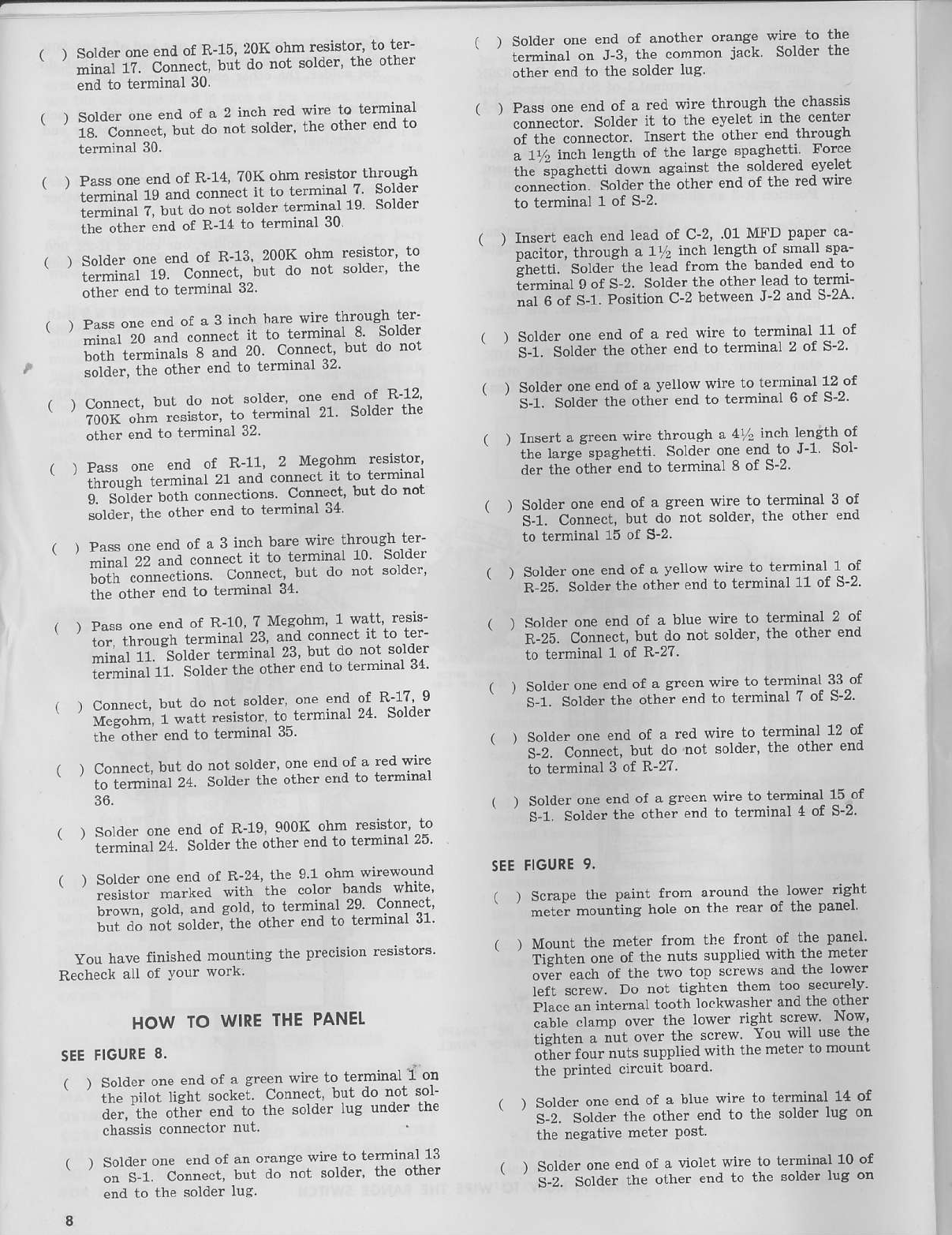
. soldpr
one
endof R-15 20K
ohmresisror'
1otPr-
' i]'ir'ri c-*", ourdo nor solder'
rhp other
end to terminal 30.
, Solder
one
"nd ot - 2 inchreo sire lo rFrminal
il.-f;;;";., b'' do nor
sorder'
the orhpr
end10
terminal 30
r pass
one
pnd
of R_14
?0KohmreFistor
lhrough
' i"#r',i is"* connocr
I'rorerminar,T
sorder
i"ii",ii,i
i, ',"'o"
'"' sorder
rerminar
re sorder
ihe otherendof R-14
to termrnar
ru
' Solder
on' eno of R-I3 200h ohm resjsror'
lo
' '.".iri"r'r' ,g. Conna'l bur do not sorder'
rhe
other end to terminal 32
, """" 6n" endof s 3 inch
harewire througr rer
-:;;i; "n,r -^'*t i ro rprminar
e sorder
ili; ."".-';;'" 8 and 20 connecr br I do not
solder,
the oLher
endLotermrnar
Jz'
" ffii":l
J":"l"1"lll""liH;"lii'1"'"ll"l'1';
other end to terminal 32
end of R-]1 2 lvlesohn resistor'
il't-"*r, Frmrnzl
2l and 'onne't il.to termrnar
ir. iii"" ""," 'onnecrions connect hxt do not
solder,
the otherendto termtnal
o+
. ' Pass
onF
pnd
of a 3 inch barewirP
ihro'rsh ler
' -Hitr;;;..""" irto
termin'l
r0 sordPr
',,.ir,
#^i:.". conne-'r'.bur
donot
soldpr'
ihe oiher end to tennrnar J4'
, r Pass
one
enooi F_!0 7 N'leSohm
l watr' resls-
' i.,.-"-,r,",,"r,rcrminai 23,
and connp.l
il to rer-
i'i""j ii l.ra'. rerminar
23bu'
do
norsorder
l"".r""i r
' solder
the
othe-
end
ro
rarnrnal
34
, I ConnP(r,
bul do not solder'
oneendol R 17 9
' i,li".rl- l-""]i rFsisro' to rerminar
04 sorder
ihe other end
to term)nar
rD
, , Connp.r,
b.ri
do notsold"r'
one
endor a red
w're
t. ienr.,r',, Zq. Soldpr
theorher
eud
ln iprm'nar
36
, ) Solo'
r onc Frd of R_19
900K ohm r"slsror'ro
' ;;:;,i tl sorder
rhe
otrer end
rotcminal 25
, , Sold"'onp endof R_24
the 9 r ohrr $'r"wouno
' ' i*"i".--'*'a wjth tl'" 'olor bands white
i.""*". *"ru andsold to lerminal 29 ConnPct
i"i'a. "'"il.ia"'ltr' orhe-
'nd IorF'minar
3r'
You have finished mounting the precisionreststors-
Recheck aU of Your work
HOWIO WIRE
THEPANEL
SEE
FIGURE
8.
r r SoldFr
onp
"nd of a Cre'nwrre
ro tprminal
I on
' ;i"-;i"' lisht 'oc\ei connecr'
but do not sor-
;;;, "G t;"- end ro rhe sordp'
Iut under rhe
chassis.orneclo.
nJ1
l So
deronp erd of "n orang"
wi"" ro Ier'inal 13
' iii-r. conn"r' tr do nor soldcr' thP other
end to the solder lug
8
r r Soldpr
one end of snolhProranAe
wjre io lbe
i"^i".r o" J-3, Ihe 'ommon jack Solder
th€
other end to th€ solder lug
{ r Pass
one
endot a red wire lhrough the c}assis
;;"""-.. soloFr
ir to rhe pvFlet
in the center
"i-ii'" """*ct*. rnsert the otherendthrouah
;1 inch len#h ot the largespashalli Force
irre ioaeherri down against rhe soldered evelel
""""""tiot. SotO". 't'. olher Fndof the red wire
to t€rminal 1 of S-2
I ) lnse$ each end lead of C-2' -01 MFD paper ca-
Dacilor,
through
a 1r. in'h leng_h
of small
spa-
!r'r"r'i. Sota"irn" lead from rhebsnded
end10
ifr.inar gor s-z Solder
tneolherlPadto termi-
i.le "i s-r' Posilion
c-2 between
J-2and S-2A
r ) Solder
on. eno of a red wire lo l€rmintl 11of
i-r. Sora"r
theorher
endto terminal
2 of S-2'
I ) Soldpr
on. end
of a vFllow
$)r" lo terminal
12
of
s-i Sora."
rheotherendro lprminal6 of S-2
r ) Ioserr
a arFen
wirethrouqha 4 inchlength
of
rt'" iu.g"'"p.gt'.rri SoldPr
one
endIo I'l Sol-
derthaoft;r endto lcrminal 8 of S-2
( ) Sold€r one end of a sreen wire to terminal 3 of
' ' i-i. C.r"*t, but d; not solder, the other etrd
to terminal 15 of S-2'
i ) Solderone end of a vellow wire to terminal 1 of
' ' R-25. Solder
the other endto terminal 11 of S-2
, , Solder
one
endot a bluF
wire to terminal 2 of
c-ii. c"'*,t, bur do not solder'
rheolher end
to t€rminal 1 of R-27
( ) Solaler
oneend of a green wire to terminal 33 of
' ' i-i. -i"rJ* tr'" othe;
end
to terminar
7of s"2'
, I SoldPr
one
'nd ot a red wite ro tctminal 12 of
' i-i. --c-**r' bur do nor soldPr'
Ine olher end
to terminal 3 of R-27.
r r Solder
one
end
ot a areen
wire10
jerminal
l5 of
' i-i. soro""
rr'" orhi end lo terminal
4 of S-2
SEE
FIGURE
9.
, , Scrape
the painr from aroundthe low€r riabt
' -"*t ,."""ii"g hole on ihe rpar of the panel
, I Mounr the mpler fror lie tronr of tbe panei'
ri.n,"t *" of lhp nutssupplied
with lhemeter
."Ei *+ "r rhF tqo rops'rews andrhe lower
lefLs.rew Do nol riShlen lhem too securery
i;r*" ." i"t"t"'t to.tt' lockwasherandthe other
;;;;;;i;-" over rhe rower titht s'rew Now'
iiJi." " ,i"t ove" rbe scrPw You $ilr u€e tre
.ii". ro," nur=
"uppti"a
wirhthp
metFr
ro
mouni
the Printealcircuit board'
, ) Solder
one
end
ol a blu' wir" to rerminal
14 of
i-i. sora"" ,t'" other end ro lhp solder
lug on
the negative meter Post
, , Solderonp end of a violet wire to terminal 10 of
i-2. So.a.. the olher end ro rhe solder
lus oD
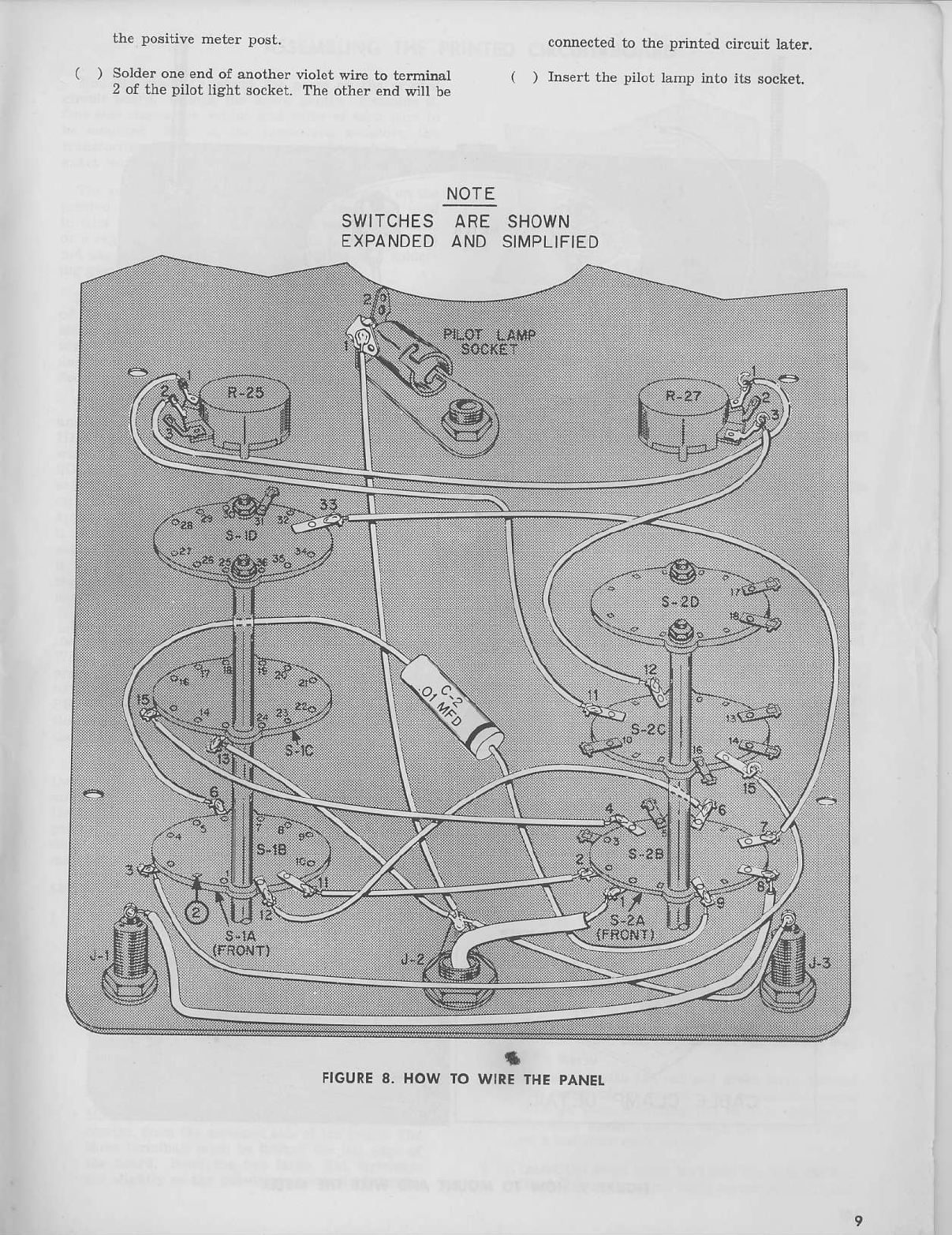
()
the positive meter post.
Solder one end of another violet wire to teminal
2 of the pilot light socket. The other end will be
connected
to the p nted circuit late!.
( ) Insert the pilot tamp into its sock€t.
NOTE
SWITCHES
ARE SHOWN
EXPANDEDAND SIMPLIFIED
rt
FIGURE8. HOWTOWIRETHE
PANEL

ry=--x
oo
I IsFAcEF
(ro
3E
YouNlEo
LAIEF)
ilUT€I
ae\**.**"
>z-
*ar**ao"-*^*a"@ _f
CABLECLAMP DETAIL
A METER
SOIJNIINC
SCREW
lo
FIGURE
9. HOW TO MOUNI AND WIRE
THEMETER

ASSEMBTING
THE
PRINTEDCIRCUITBOARD
You are .eady to mount ttle parts on the priDted
circuit boa.d. Eandl€ the board seDtly. Exarine it.
One side shows the outline and value of each part to
be mounted. That is, the capacitors, resisto.s, the
transformer, the battery, etc., are picturcd in th€ir
The solderirg technique which MUST be used on tbe
printed circuiL is somewhat ditferen{ from tlal used
io wire the swilches. Usp a 50-watt solderina p"ncil,
or a regular type solderiDg iron with a small tip. Do
not use an iron of higher wattage rating o. a solder'
ing gurl.
Mount the components
on the board. Bend the lead!
of the resistors at right anglesto the body of tle re-
sistor so the resistors will lay flat on the board. In-
se the leads tlroush the proper holes in Ure boad
and bend them to hold t}le part firmly in position,
SeeFi8u.e 10.
Touch the connection to be sold€red with the solde.
atrd the iron AT THE SAME TIME. DO NOT PRE-
HEAT the connection. This may daEage the pnnted
wiriDs pattem. REMOVE THE IRON AND THE
SOLDER as soon a! tle flux froD the core of the
soliler flows out around the comection. The solder
on the conDection should have a shinv"'silverv"
r the contrection has a dull appearance'
lils a cold solder joitrt. Usins more sold€r' again
solaterthe connection.
Do not useso much solder that
it flow! off the printed wiring otrto the board This
may cause an intemittent, or a short, between con-
Before you solder the pins of the tube sockets to
the p.inted wiritrg, insert the tubes in the socket
When you solder the pins of the tube sockets to the
pdnted wirins, touch the soldering iron and tle solder
to the pin of the tube socket, and NOT TO THE
PRINTED WnING PATTERN. When tI€ solder
flows down onto the printed wirins REMOVE both
the solder and the iroD
After you have soldered all of tlle conrectiom on
lhe Drinted board, but before you pul in the cable.
ex'
amiie the printed wiriDg sideof ihe board closelv. U
the flux from tlle core of the solder has flowed off the
olinted wirins patlern onto the board, remove it wit]l
ienaturea aliohol. This condition, ir not corrected'
may cause a leakage Patll.
SEE
FIGURE
II.
( ) Mount the g-pin niniature socket for V-2, tlte
12AU7, from the screened side of the board.
This socket can be mounted only one way Lirc
up the notch in the socket with the half_moon
shaped notch in the board. Put the12Au7 in the
socket. Solder one end of a 3/a
inch bare wire to
pin 1. Solder the other end to pin 6. Solder au
pins to the board.
( ) Mount the ?-pin mi etur€ socket for V-1, the
6AL5. Put the 6A15 in the socket Solder au
pins.
( ) Mount R-34, 10,000 ohm! AC Balance poterti-
ometer, frcm tle screened side of the board. The
three te.minals must be toward the left edge of
the boad. Bend tlle two larse, flat te.minals
out slightly so the potentiometei tu held firmly.
FIGUREIO. HOW TO MOUNT
AND sOLDER
PARTS
ON THEPRINICDCIRCUIT
AOARD.
Solde.eachterminal and also the tq'o lalge ftat
( ) Mount R-29, 10,000
ohDs DC Calibration poteD-
Uometer ir the samemaDde.. Solder the large
flat termilals aDdtbe two Bnall telmirsls.
( ) Mouni R-26, 10,000 ohms AC Calibratio4 po-
tentiometer iD t}le samemarlner witn the thee
teminals towad the te.miDals of R-29. Solder
the thr€e termiDals which go into tle printed
wiring.
( ) Mourt CR-1, the rcctili€r, by in8erting the two
te.miDals tl.ough the holes iD the upper left
corDerof the board. The pditive side must be
toward the right. Bendth€ two teminals slight-
ly to hold CR-1firmly. Solder botl terminals.
( ) Mount C-6,the 20 MFD, 150Velectrolytic filter
capacitor, with t]le "+" end next to the r€cu-
fier. Solderboth leads.
( ) Trim the lea& of T-1, the pow€r tran-sformerto
the following lengtls :
The black lead toward the upper right comer
to tY2".
Theotherblack leadto 6".
Botll sreeD
leadsto 1%".
Both rcd leadsto 2".
Removet]}e insulation fmm ya" of ttle ed of
eachlead. Hold the lead witl plien closeto tle
body of tlle traDsfomer as you remove the i!-
sulatioDsothat you donot tear the lead through
the wrappiDg arouDdtle willdbs of the tran8-
folmer. Now, cost the stripped endof eachlead
rit}r Bolder.
Mount T-1 witn tle r€d and grcetr leaals
toward
l.hecetrter
of L}leboard. Usea machinescrew
tl.oush each moutrtiDg tab of T-1, thmuah a
fbt fiber wsshor, aDdthmugh the board. Tiaht-
en a nut ov€r each screw.
( ) Insert tlrc short black lead into the hole mtrked
Bleck Pri. in the upper riaht corner of th€ boed.

R-34
10K
R-29
toK
R-26
10K
FIGURE
II. MOUNTING
TXE PARIS
B.nd it slichtly so it will stav in position and
solde! it. The olher black lead will be conn€cred
( ) Insert the green leads into the holes marked G'
Bend them slightlY- Solder th€m.
( ) Inse.t the realleads into the two holes marked
R. Bend them slightlv. Solder both
SEE
FIGURES
II AND 12.
( ) Mount the battery bracket as shown iD Figule
12. Insert a machine sclew through the battery
retaining clip through the centerhole in the bat_
t€ry br;kei, tlroush a flat fib€r washer, and
rhroueh the hole in rhe prinied circuit board
T'sht;n a nul onlo lhe screw Use the Ihin
sdew throush the hole in the end of the bracket
near T-1, anil through the cilcuit board. Place a
small flat metal washer over the scr€w on the
printed wirirg side of t]le board and tighten a
nut over the screw
12
ON IHE PRINTED
CIRCUIf
BOARO
You are now ready to mount the resisto$ and
capacitors
onthe pnnted circuit board.
( ) Mourt R'9, 3.3 M€sohm resistor (orenge,
oraDge,
ar€en)as shown
ir Figurc 11
( ) Mount C-4, .005 MFD disc capacitor.
( ) Mourt R-18,
150Kohm resistor (brown'green'
yelow).
( ) Mount R-28, 150K ohm resistor (brown, g'€en'
I
I
yellow).
( ) Moult R-33,
ange)
( ) Mount R-31,
Iow).
22K ohm resistor (r€d, red, or-
220Kohm resistor (red, r€d' YeI-
( ) Mount R-32, 100 ohm resistor (brown' black,
( ) Mount C-5, .005 MFD disc capacrtor'
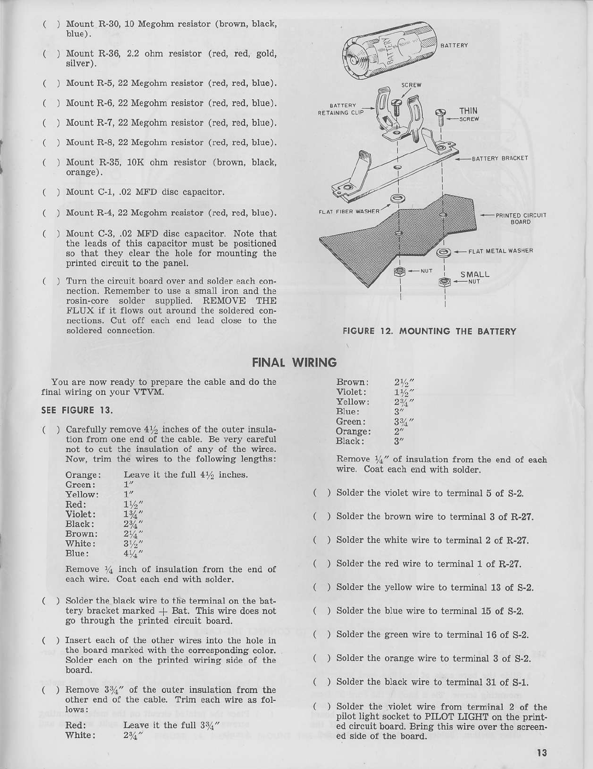
( ) Mount R-30,10MegohmreEistor
(brown,
black,
blue).
( ) Mount R-36,2.2 ohm resistor (red, r€d, gold,
silver).
()
()
) MountR-5,22Megohmresistor(r€d,
red,blue).
) MountR-6,22Mesohmresistor(red,
red,blue).
) MountR-7,22Mesohmresistor(red,
red,blue).
) MountR-8,
22Meaohm
resistor(r€d,
red,blue).
) Mount R-35,10K ohm resistor (brown, black,
Mount C-1,.0?MFD disccapacitor.
MountR-4,22Mesohmresistor(red,
red,blue).
Mount C-3,.02MFD disccapacitor.Note that
th€ leadsof this capacitormust be positioned
so that th€y clear the hole for mountins the
p ntedcircuit to the panel.
Turn the circuit boardoverandsoldereach
con-
nection.Rememberto usea smalliron andthe
rosin-core solder Bupplied. REMOVE THE
FLUX if it flows out aroundthe solderedcon-
nectiotrs-Cut off eachend lead closeto the
soldercd
connection.
FINAT
You arenowreadyto prepare
the cableaDddothe
final wiring onyour VTVM.
SEE
FIGURE13.
( ) Carefully
remove4% inchesof the outerinsula-
tion from oneendof the cable.Be very car€ful
not to cut the insulationof any of the wires.
Now, trim the wir€s to the followins lengthsi
Orange: Leaveit the full 4% iDches.
Green:
Yellow:
6) THIN
E
-**',
WIRING
Yellow: 211"
Blue:
112'
Bron11: 2Y4"
White: 3r/2'
BIue: 4Y1"
Remove
y1 inch of insulation
from the endof
eachwire. Coar
ea.h
endwjthsolder.
( ) Solderthebtackwireto ureterminal
onthebat-
tery bracketmarked
+ Bat- Thiswire does
not
gothroughrhe
prinred.ir.uil board.
( ) Insert eachof the other wires iDtothe holein
the boardmarkedwith the correspondi
g color.
Soidereachon the p?inted
wiring side of t]le
( ) Remove37a" of the ouler insulatior from the
other endof the cable.Trim each
wire as fol-
Red:
Violet:
Black:
Red:
7Y2"
Leaveit the fuu 31i"
@. FLrmilLM$s
g*Nr
FIGURE
]2. MOUNTINGTHE
BATTERY
Viol€t:
Orange:
Black:
Remove ya" of insulation from the etrd of each
wire. Coat eacb end with solder.
( ) Solder the violet wire to terminal 5 of S-2.
( ) Solderthe b.own rrirc to terminai 3 of R-27.
( ) Solder the white wire to terminal 2 of R-2?.
( ) Solder the led wire to terminat 1 of R-27.
( ) Solder the yellow wire to telminal 13 of S-2.
( ) Sold€r the blue wire to terminal 15 of S-2.
( ) Sold€rthe gr€en v'ire to terminal 16 of S-2.
( ) Solde. the oranse wire to teminal 3 of S-2.
( ) Sold€r tlje black wire to t€rminal 31 of S-1.
( ) Solder the viotet wire from temiltal 2 of the
pilot light socket to PILOT LIGHT on the print-
ed circuit boad. Bdns this wire over the scr€en-
ed side of the board.
l3
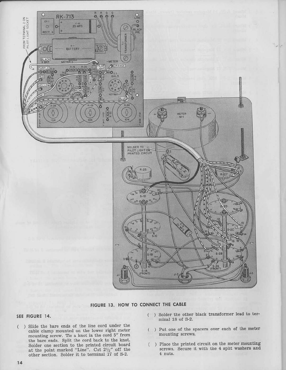
FIGURE
]3' HOW TO
5EE
FIGURE
I4.
( ) Slide thc ba.e ends of ihe line cord uDder the
'-rb
a lan
t olr
" d or rhn
.uvpr
rr8hl
n'l r
mounting scre$. Tie a knot in the cord 5" from
the bare ends. SPLiL
the co.d back to thc knot-
Solder one section to the printed circuit board
at th. poilL marked "Line". Cut 21r:" off the
other scction Solde. ii to terminal 1? of S_2.
t4
CONNECT
THE
CABLE
( ) Solder the other black transformer lead to ter_
mlnal 18 of S-2.
( ) Pu! one of the spaccrs over cach of the meter
mouniing screws.
( ) Place the ldnted circuit on the meter mounting
screll's. Secureii with ihe 4 sPhLwashels and

@
o
@
o
FIGURE14.HOWTOMOUNT
IHE PRINTEDCIRCUIT
BOARD t5

a
PRETIMINARY
ADJUSTMENTS
CAUTION:
NEVER
TOUCH
ANY
PART
OF
THEWIRING
WHILE
THIS
INSIRUMENT
I5
PLUGGED
INTO
A POWER
OUTLET.
NEVERUSE
OR
TESI
THEVTVM
ONOR
NEAR
A GROUNDED
METAL
BENCH.
RADIATOR,
SINK,
OR
OTHER
GROUNDED
METAL
OBJECT'
| ) Asain check
1ospe
lhal lhe while linF on lhe
k;ob of S-l lines
!p wilh lhe scaleon lhe lroni
Danel. If not, loosen the nut and move S-1 so
itut it oo"" Retishten the nut'
( ) Also check S'2.
{ | Rorale lhF shafrs
or lne oHMS ADJUST 'on'
trol, R 25, and _hP ZERO ADJUST coDlrol'
n zi, tutty couorerctort<wise
Pla'e a smallknob
on eactr
ilarr so lhat the whirP linP
poinls to
the lower left. Tighten eacit set screw-
| ) Plue lhe line.ord inro a ll7 voll' 60 cycle AC
outict. NEVER conne(r rhe VTVM lo direct
""-"nt o" yo" will ilamage the instrum€nt' If
y- -n "oi celtain as to the power available'
check rtith vour local power companv'
( ) Turn the VTVM on set the FUNCTION switch
' ; either + DC or DC volts. set the RANGE
switch to 1.5 votts The pilot lamp and tubes
;hould lisht Turn the kDob of -tle ZERO AD-
.rUST co;trol The meter needle 1{'ill deflect
ovcr at least Part of the scale'
( , Leave
the VTVI\'I
on wnilevou prPpzre
ihe lest
-eads.
This will give lhe Lubes
amplp
rim' for
wamup before calibration
:tr.tii: .""::,].i',,iill'
r*rx.9rlfi.,1'T8I'1"J,"
TEITIEAD ASSEMBI.Y
sEE
FIGURE
]5.
Th€le are three test leads to be prepared for vouf
VTVM.
( ) Removethe small setscrewfrom the cable plug
anclremove the spdng ftom the plua Slide the
sDrine LlarR' hole first) over one end ot lhe
slield"edcab-h. Remove rr inch of rhe outer in-
sulation from one end of the cable Unravel the
brsid and bend it back over the sp ng' Remove
% inch of the insulation from the inner conduc-
i;r. Insert the cable analsprins into the open
€Ddof the Plug.
The inner conductor must fit into the small hole
J the pl"g. Th€ braid and spring should fit
into thi plrls so that the setscrew wiu tishten
otr the sp;int. Tighten the setscrew solder the
inner conductor to the ey€Iet.
a ) Remove the black handle from the prod tip
Slide the haDdle over the other end of the
shielded cable.
r ) Remove i inch
of thaouterinsularion
from th'
oLl* ena
of the
shiplded
cable Trim the braid-
e.Ishieldins
back
even
wirh the rut otf insula-
tion. Remo;e r in'h of the jnsulation
from the
in.er conductor. Form a small hook in it'
. ) Cut oDe
leaal
of R-37, 1 mesohm 5% reBistor,to
"" Form a small
hool in ir. Hook R-37
LothP
i"-nerconducror
ol rheshiplded
cable.
Crimp thP
two togetler. Solder the conDection'
j
*- * L-r';
FIGURE
15.HOW
TOASSEMSIE
'HE TEST
TEADS

()
()
Trim the other lead of R-3? to % inch from the
body.
Inseri the .ld inch lead into the prod tip and out
the smalt hole near the threads on the prod tip.
Pull R-3? into the prod tip. Wrap the tead
around the baseof the prod tip. Screw the nut
back onto the prod tip. Tighten it securely so
that the lead of R-37 is held very firmly.
Removerhe redhandlefrom rhe olhFrprod rip.
Slide it over the red test lead wire. Remove 5ri"
of the insulation from one erid of the wire. Coat
the fine wires with solder. Insert the end into
the prod tip so the bared end comesthroush the
small hole. Wrap it around the baseof the p.od
tip. Screw t]Ie nut on very tightly.
Uns.rew the short red insulator from the tip
plug. Sljde
jt overtheothcrendof Lheredwire.
Remove
1"'' of the insu'ation.Tvist tl'e wires
and coat them with solder. Fill the tip plug
with solder. Insert the ba.e end into tl1e tip and
let the solder cool.
Prepare one end of the black test lead in the
The OHMS ADJUST potentiometer, R-25, positions
the meter needle at the extreme riAht of the scale
when the function switch is in the OHMS position.
The DC VOLTS chaEsisconnecto.is usedfor all DC
voltage measur€ments with the DC test prod. Tbe
black test lead must be plugged in the COMMON jack
for all of these measurements.
The AC-OHMS jack is used Jor all AC voltage atrd
resistancemeasurements. The red test lead must be
plugged into this jack. The black test lead must also
be plugged into the COMMON jack.
The COMMON jack is conn€cted directly to the
panel of the VTVM and is the return point for all
READINGTHE
sCAIESOFTHEMETER
Study the face of the meter on your VTVM. A rc-
production of the meter scales is shown below. You
will notice the scalefor r€sistanceis the top red scale.
Read this scalef.om left to right. Each of the 7 pos!
tions of the RANGE switch is marked with a resist-
ancemultiplier. h the Rx1 position any value bet]veen
0 and 1000 ohms may be read directly. Ten is the
multiplier for the next position, 100for the next, 1000
the n€xt, 10K (where K indicates 1000), 100K and 1
meg or 1,000,000.Therefore, the largest resistance
which can be measu.ed is 1000 megohms.
l(nighl
( ) ReDove %" of the insulation from the oth€r end
of the black test lead. Twist the wires and coat
th€m with solder.
( ) Loosen the screw at t]le back of the clip. Form
a hook ir the solder coatedwires. Hook the wire
around the screw in a clockwisedirection. Tight-
en the scrcw. Now, bend the two small prongs
at the back of the clip do]r'n around tlje insula-
tion of the lead.
You have fiDished wiriDg your KNIGHT \/.TVM.
Check aII of your work very carefully. A few exta
minutes spent checking your instrument may save
hours of trouble-shootina. Be especially sure all the
priDted circuit conrcctions are shiny.
MOUNIINGTHEHANDIE
( ) Push the handle mounting studs through trle
holein eachendof the handle.Insert the stud
throughthe holein the metercaseon oneside.
Use a large flat metal washer,a shakeproof
washerandoneof the largerhexnutsto fasten
it.
( ) Mount the other stud in the other sideof the
USEOFTHECONTROLS
The FUNCTION SWITCH, S-2, serves two pur-
poses. One,turns the power ofl when the switch is in
the off position. Two, selectsthe operating function
desired.
The RANGE SWITCH, S-1,provides wide choiceof
ranges for voltaae and r€sistancemeasur€ments.
The ZERO ADJUST, R-2?, coDtrols meter needle
position at the leIt zero pdition or sets the needle at
the zero-center, "0", when the function switch is in
VOLTS position.
You will notice that the next two scales (black) arc
brack€ted and marked D.C.v. or R.M.S. AII DC and
AC rms voltages are read on th€se two scales. The
vaiue of the voltage to be measured deterrnin€s which
scale to use. When making voltage measurements
atways start on a high range atrd work dowL Make
the final readins at mid-scale or higher for greater
acc racy. You will also note that the RANGE switch
is mark€d with numbers which are multiplierc for all
of the voltage scaies.
The next two scales(red) are marked P-P, or peak-
to-peak. The p€ak vaiue of a sine q,aveis 1.414time!
the rms value.Therefore, peak,to-peakvalues arc 2.83
times rms- Peak-to-peak values are read directly on
the two red scales.The first red scale,marked 0-40,
coresponds to the fi.st black scale.This is irdicated
on the meter face by 15 R.M.S. in parerthesis. The
secondred scalecoresponds to the secondblack scale
andis similarly marked 50 R.M.S.As an example,aup-
pose the RANGE switch is set at 15V and an AC volt"
age of 10 volts ms is to be measured. The meter
needlewilt stop et 10 on the ms scate.At the same
17

time you can reaaltbe peak{o'peak value of the sine
wavein the correspondins P-? scale,
or 283 volts No
calculations are necessarv
to convert rms to peak-to-
Deak
or viceversa. Greater accuracv is assuredaswell
is savine you time. Peak'to_peak voltages are used
tor waveloim measurementssuch as are encountered
in television service {ork.
The use of the decibel scnle and zero center are
explain€al in the section of this manual 'USING
YOUR VTVM'"
CATIBRATION
Before vou calibrate iour VTVM, b€ sure the meter
reerlle is at zero on the left side of the scale.
r ) Turn the instnment off. If the needle
is not at
the screw above the Pilot light'
IIse a scriber. or comparable instrument' to
move the zero'adjustment lever either risht or
left as tequired to bring the meter needl€ to
CAUTION:
Be
verv<oteful
thoi vou do notinseri
the s.riber
too deep. It lhis is done the Pointer
sprins will be domosed. The stonddrd
RETMA
wononty doesnol cover
such
dcnoge'
Replace the screw Turn the instrument on
aAain
( ) Set the FUNCTION switch, S-2, to the +DC
posirron. Aolusrment of lhe zERo ADJUST
control should move rhe needl" approximatelv
one-half scale R€set the ZERO ADJUST con-
trol for zem set S-2 to the DC position lf
there is any change in the zero, re-adjust the
ZERO ADJUST control Repeat this procedur€
urtil there is no change in the z€ro when the
FUNCTION switch is changed back and forth
ftom +DC to DC
DC CAI"IERATION
Ins€rt the black pin ja€k into the common plus
Attach the DC volts test cable to the comector on
Set the FUNCTION switch to +DC
Set th€ RANCE switch to 1 5 volts-
Use tlle battery which is included with vour VM'
Attach the DC test prod to the positive end of the
battery analthe commm test lead to the negative end
Adiust R-29. the DC calibraie control on the print-
ed ciicuit board. so that the needle
of the meter rests
exactly over the red dot at the extreme dAht edAe
of
Set the FUNCTION switch to -DC
Connect th€ test leads to the batterv iD opposite
polarity.
There should be no change in the position of the
n€ealle
over the red dot. If there is, adjust the DC
calib.ate cotrtrol until there is no change when switch'
irg back and fortl from +DC to -DC.
l8
AC CAUERATION
Set the FUNCTION switch to AC volts.
Insert the AC-OHMS pir jack into the red piD plug.
Let the leads hang free DO NOT hold tllem to
eliminate any hum Pickup
Set the RANGE switch to 1.5 volts
Adiusl R-3{, tbe AC BalanceCoorrol
on t}e pr'nl-
ed.ircuil board,
sothat lhe meter
treedle
reailEexacl-
ly zero on the left lide of the scale.
Set tle RANGE switch to 15 volts.
Touch the AC-OHMS test prod to the sreen lead of
T-1, which is not grounded.
The common test prod is already grounded to com-
Adjust R-26,the AC Calibrate Control on the pnnt-
ed cir€uit board, for 63 volts
You also can make this adjustment bv measuriDg
the voltage between the two connectionsof the liDe
Set the RANGE switch to 150volts.
Adjust th€ AC Calibtate Control for 11? volts.
OHMS CALIBRATION
Tum off the VTVM
IDstall the battery on tl1e pdnted circuit board
Turn th€ VTVM on
S€t the FUNCTION sv,ritch to ohms
Adjust R-25 for full scale.
Touch the AC-OHMS ard COMMON test leads to-
gether. The meter needle should indicate zero ohms'
FINAT
ASSEMBI.Y
( ) Install t}le met€. in the cas€ so that ttle clamp
at the top of the panel hooks against the inside
of the flanse in the css€
( ) Use the two self-tapping scr€Y{s through the
holes in the panel. Tighten them into the hole8
in the case.
HOW THEKNIGHT
VTVM WORKS
SEEFIGURE
16.
The KNIGHT VTVM utilizes the basic principle of
a vacuum tube which is: A tube can amplifv witlout
takiDs oower
from the vohagesourceapplied
to its
sri{r.ihis instrument
isexrrenelv
sensitive
andstable
;ecause
everym"asurement
is made
electronically.
A sensitive200microamperemeter is the iddicati4g
comDonent.The meter is in the cathodeci.cuit of t,he
rzeirZ twi" triode t be, V-2. P,-27,t}j,ezero adjust
control, bslancesthe two sectionsof t]!e tube Bot'hat
there is no indication on the meter due to both sec-
'ions of l}e (onrrol beinA
equatwhen
rhereis no ap-
plied voltaae. When a voltage to be measuredis f;d
inLo the gdd of V-2, this batance is upset and the
voltage can be read directly on the meter. The test
voltage and the met€r indicating cuuent are direcfly
proportionat, so that the meter is calibrated direc y.
The meter is protected, because
as stated before, the
voitaAe to be measured is applied to the tube rather
The lpsl vollage
applied
,o therubFis a maximum
oJ 3 volts. HiAher test voltages are reduced through
the voltage divider witl1 a total resistanceof 10 m*-
ohms. The DC tesl prod includes a 1 megohm resis-
lan{p in addiiion. ThF hiAh inpLl impedance
ot rhe
VTVM enables
you to mak" measurements
in uost
circuits without disturbing the circuits_
When the instrument is used for makina AC mea,
surements, the 6AL5 tube, V-1, acts as a full wave
rectifier. The output of this tube is direc y propor-
tional to the AC voltage to be measured. The DC
output is fed through the voltase divider network the
same as for DC measurem.nts and is indicat€d in ex-
actty the same way.
On the 500 and 1500 volt scalesfor AC measure-
hents, the voltage to be measuredis reducedthrough
R-3 and R-2 before it is apptied to V-1. This featu;e
p.otects V-1 and all follorving circuitry sincevoltages
greater than 150 votts ar€ not applied to the tub€.
The AC scales are calibrated in both RMS and
peak-to-peak values.
The AC balancecontiol pmvides proper meter indi-
cation for the applied AC vottage by cancelling out
the contact potential between etementsof V-1. Th€
contact potential is cancelled out by the bucking
voltaae provided by the AC halance control. This
control permits changins from AC to DC without re-
adjustina the zero of the meter.
A.t.5 rcli balrery is connected
Llrougha spries
of
mDrlrpxFrs
andthc unknown
resistance
ro be
measu!-
ed oeatinA a voltaAe divider acrosstre battery. part
ot lte resulrirg bal|ery vottaee is aDDlied
ro rhe
l2AU7 .6u"ina a dFnccrion
in the mer;;. For rhese
measurementsthe meter is catibrated in ohms.
There are two accessory probes which will mak€
your KNIGHT VTVM an even morc versatile instru-
menl. One is rhe high.voltasep"obe
$hich extends
thF rangp
of rhp instrumpnt
to 50.000
volts,when
on
the 500 volt scale-
Thc other trobe is rhp h'Ch.frequcncyprobe. l.his
probF
rurlhar p.mits work in RF circuitsup ro 250
megacycles,yieldins a direct reading in RMS volts.
The stock number of eachprobe is ljsted at the end
of the Parts List.
USING
YOUR
VTVM
CAUTION:
NEVER
TOUCH
ANY pART
OI THE
WtX-
ING
WHILE
THEINSTRUMENT
ISPIUGGED
INTO
AN
AC OUTLET.
Do not u.€ the VTVrnon o srounded
merol ben.h, rodiotor,or orhergrounded
obied.
Remove
lhe powe. trom tbe equipment
uDder
test
beforcyou attacb lhe tf,sl teads.IJ lbis caDtrol
be
done,useSPECIAL CARE not to touch grounded ob-
jects. Use only one hand at a time. craEp the test
prods on the handi€s,never on the metal tips. Stand
on a well insulated floor.
Ir is a good po.i.y lo dischsrAe fiher capacitors
before lest leads are attached
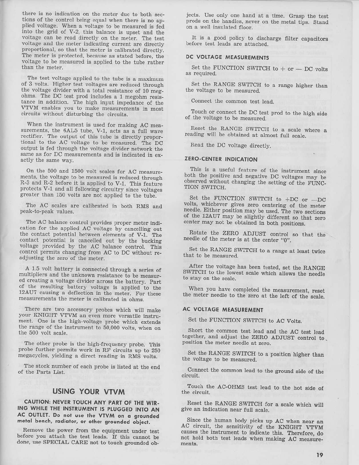
DC VOLTAGE
MEASUREMENTS
Set the FUNCTION SWITCH to + or - DC volts
. SFIthe RANCE SWITCH to a range hiAherlhan
rne vortage to be measured.
Connect the common test lead.
-Tourh or connect
rhc DCrcsr
prodro rhc hiAh
side
or rne voLrage
to be measured.
Reset rhe RANGE SWTTCH to a scare wherc a
reading wiU be obtained at almost full scare.
Read th€ DC voltage direcuy.
ZERO.CENTER
INDICATION
This- is a usefut iparurp of Lle insrrumenr srnce
born the posiuve
aod negstivF
DC vottages
may be
observed
withourchanAing
rhesprtinC
of ihe FUNC_
TION SWITCH
set rhetuNcTtoN swITcH to rDc or _ Dc
gives zero centering of Ue meler
neeojc.!:lther posilion may b. used.The two sec[ioDs
or the 124U7 may be stighrly difterenr so thar zero
center may not be oblained in bor}I posiLiuDs.
Rotzre_
th. ZERO ADJUST .ontrol so lbat the
neeore
or rbe meter i3 at the center .,0'..
. 54 thr RANGE SwmCH to a range ar least twice
rnat lo be measured
A-tter the voltage has been tested, set the RANGE
SWITCH to the lowest scatewhich allows the needle
to stay on the scale.
. When you have completed the measurcment, reset
the meter needle to t]le zero at the left of the scale.
AC VOLTAGE A.IEASUREMENI
Set the FUNCTION SWITCS to AC Votts.
Short the conmon test tead and the AC test lead
toAetner, and adjust the ZERO ADJUST coDtrol to.
position the meter ne€dle
at zero.
. Se1Ihe RANGE SWITCH to a position
higher
than
rfie voltage to be measured.
_
Connect tle common lead to the ground side of the
Touch the AC-OHMS test tead to the hot side of
Reset the RANGE SWTICH for a scale which wi]l
give an indicatioD near futl scale.
Since the human body picks up AC wben near an
ac crrcuil. lhe sensirjviry of the KNICHT VTtrM
causes tlie instrument to indicate this. Thereforc, do
not hold both test leads whed makiDg AC Eeasure_
l9
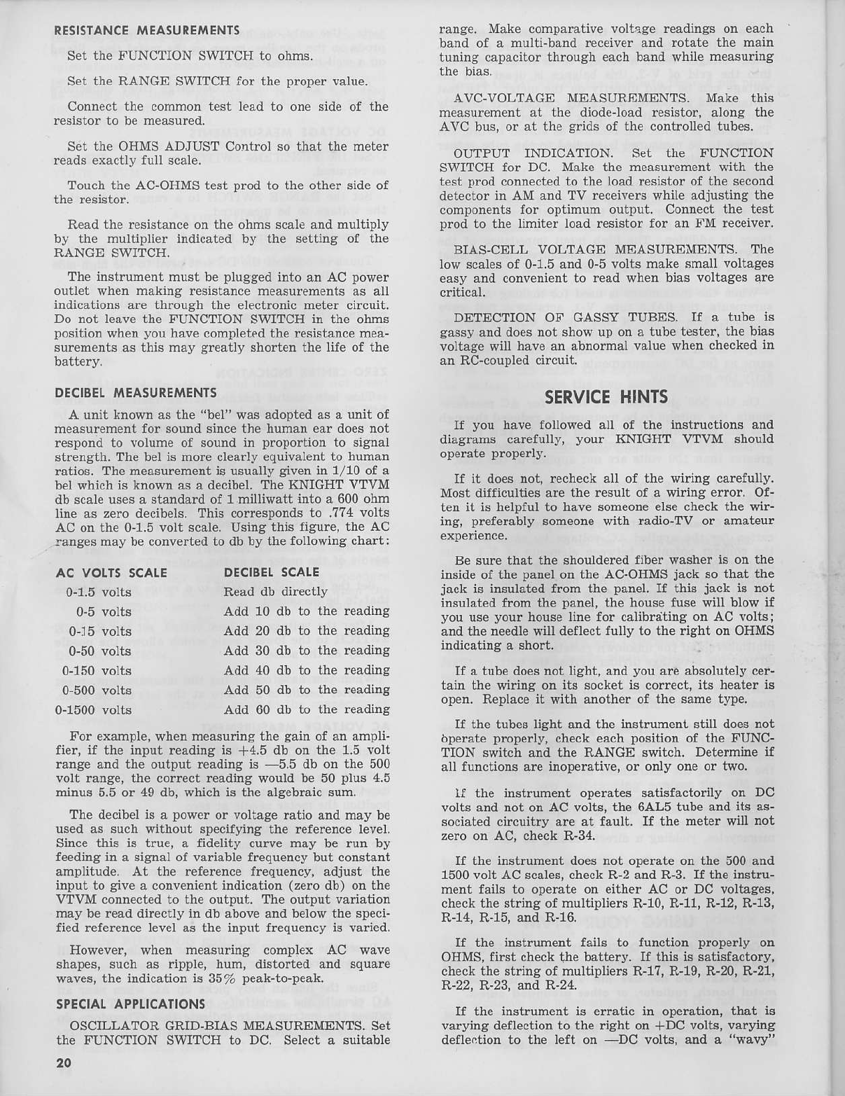
RESISTANCE
EASUREMENTg
Set the FUNCTION SWITCH to ohms.
Set t}1eRANGE SWITCH for the proper value.
Connect the common test lead to one side of the
resistor to be measured.
Set the OHMS ADJUST Coatrol so that the meter
reads exactly fuU scale.
Touch the AC-OHMS test prod to the other side of
Read the resistanceon the ohms scaleand multiply
by the muttiplier indicated by the settiDg of tlle
RANGE SWITCH.
The instrument must be plugged into an AC power
outlet when making resistance measurements aE all
indicauons ar€ throuah the electronic meter circuit.
Do not leave the FUNCTION SWITCH in the ohms
position when you have completedthe resistame mea-
surements as this may greatiy shorten the life of the
DECIEEI.
MEASUREMENTS
A unit knov{n as th€ "bel" was adoptedas a unit of
measurement for sound sincethe human ear doesnot
respond to volume of sound in proportion to stgnal
strenAth. Th€ bel is more cl€arly equivalent to human
rutios. The measurcment is usualty given in 1/10 of a
bel which is knowr as s decibel. The KNIGHT VTVM
db scaleusesa standad of 1 milliwatt into a 600 ohm
line as zero decibels. This correspondsto .774 volts
AC on the 0-1.5 volt Ecale-Using this figur€, the AC
rangesmay be conveited to db by the following €ha!t:
ranse. Make comparativevottsgereadingson each
band of a multi-bandrcceiverand rotate the main
runing
capacitorthrouaheach
band$hilemeasuring
AVC-VOLTAGE MEASUREMENTS. Make this
m€asurementat the diodeload resistor, alons t}re
AVC bus,or at the sdds of the controuedtubes.
OUTPUT INDICATION. Set the FIJNCTION
SWITCH for DC. Make the measurementwith the
test prodconnect€dto the loadresistorof the second
detectorin AM andTV receiverswhile adjustingthe
componentsfor optimum output. CoDnecttl}e test
pmd to the limiter load resistorfor an FM receiver.
BIAS-CELL VOLTAGE MEASUREMEIVTS.ThE
low scalesof 0-1.5and0-5
voltEmakesmallvoltager
easyand convenient
to readwhen biasvoltages
are
critica-l.
DETECTION OF GASSY TUBES. ff a tube is
ga€sy
anddoesnot show
up ona tubetester,thebias
voltasewill have
an abDomalvalu€when
checkedin
an Rc-coupledcircuit.
SERVICEHINTS
r you have followed all of the instructions and
diaglms carefully, your KNIGHT VTVM should
If it does not, rccheck s-11of tl1e wiring carefutly.
Most difficulties are tlle r€sult of a wi ng enor. Of-
ten it is helpful to have someone
else check the wir-
ing, preferably someonewith iadio-Tv or amateur
Be sure tlat tle shoulderedfiber washer is on the
inside of the panel on tlle AC-OHMSjack so that t}le
jack is insulatedfrom the panel.
ff this jack is not
insulated from tle panel, the house fuse will blow if
you use
you. houseliDefor calibr:ttingon AC volts;
andthe needlewill deflect fulty to the riaht on OHMS
indicatins a sho .
If a tubedoesnot liaht, and
you areabsolutelycer-
tain t-hewiring on its socket
is correct,
its heate!i3
open. Replaceit wit}l another of t}le 6amet]?e.
If the tubes light and the instrument still doesDot
bperate
properly,
checkeachposition
of the FUNC-
TION switch and the RANGE switch. Determine if
au functions are inoperative, or orly oneor two.
If the inshument operates satisfactorily on DC
volts and not on AC volts, the 6AL5 tube and it8 as-
sociated circuitry are at fault. If the mete! will not
zeroon AC, checkR-34.
If the instrument doesnot operate otr the 500and
1500volt AC scales,checkR-2 and R-3. ff t}le instru-
ment fails to operate on either AC or DC voltages,
checkthe string of multipli€rER-10,R-11,R-12,R-13,
R-14,R-15,andR-16.
ff the instlument fails to function properly oa
OHMS,fiNt checktlte battery. If this is satisfactory,
checkth€striDsof multipliersR-17,R-19,R-20,R-21,
R-22.R-23.andR-24.
ff tle instrument is erratic in op€ratroD,tlat i6
varying d€flection to the riaht on +DC volts, varyirg
defle.tion to the left on -DC volts, and a "wavy"
AC VOLTg
SCAIE
0-1.5volts
0-5 volts
015 volts
0-50
volts
0-150volts
0-500volts
0-1500volts
DECISELSCALE
Read db directly
Add 10 db to the leading
Add 20 db to the reading
Add 30 db to the leading
Add 40 db to the readins
Add 50 db to the reading
Add 60 db to the reading
For example,whenm€asuringthe gainof anampli-
fier, if the input reading
is +4.5 db otrthe 1.5volt
rangeandt]le output r€adinsis 5.5db or the 500
volt raDge,the couect readirg v{ould
be 50 plus 4.5
minus5.5or 49db,whichis tne algebraicsum.
Thedecibel
is a power
or voltageratio andmay be
usedas suchwithout specifyingthe referencelevel.
Sincethis is true, a fidelity cuwe may be run by
feedinain a sisnalof variablefrcquencybut constant
amplitude. At the referencefrequency,adjust the
input to aive
a convenientindication
(zero
db) onthe
VTVM connectedto the output. The output variatioD
maybereaddirectlyin dbaboveandbelowthe speci-
fied refererce level as t}le input frequeDcy is varied.
However, when measurins complex AC wave
shapes,such as ripple, hum, distorted and square
waves,the indicationis 35% peak-to-peak.
SPECIAL
APPI.ICATIONS
OSCILLATORGRID-BIASMEASURIMENTS. Set
the FUNCTION SWITCH to DC. Select a suitable
20
Table of contents
Other Allied Radio Test Equipment manuals


Popular Test Equipment manuals by other brands

DARKSTAR TECHNOLOGIES
DARKSTAR TECHNOLOGIES WIREMAP D620 Guide to Operation

Testboy
Testboy 111 operating instructions

Optex
Optex Water It TC-3000-DI instruction manual

Agilent Technologies
Agilent Technologies 16048A Operation and service manual

PCB Piezotronics
PCB Piezotronics 482B11 Installation and operating manual

Hanna Instruments
Hanna Instruments HI98330 instruction manual


