kincrome KP8501 User manual

BATTERY TESTER
ANALYZER
12V DC,
100 2000CCA, 30220AH
KP8501
ED2/May 17
EASY TO
READ
DIGITAL
DISPLAY
ACCURATE
RESULTS
IN
SECONDS
100 -
2000 CCA
CAPACITY

BATTERY TESTER ANALYZER
1
Table of Contents
Know Your Product .................................... 1
General Safety Instructions ...................... 2 - 3
Operation.................................................... 3 - 10
Installing CD Drivers ................................. 10
Warranty..................................................... 14
1
9
210
3
7
8
Know Your Product
1. Up Key
2. Down Key
3. Exit Key
4. Enter Key
5. Mini-USB Socket (Side of Product)
6. Digital Display
7. BLACK (-) Negative Battery Clamp
8. RED (+) Positive Battery Clamp
9. CD (Operation Software)
10. USB to mini USB Cable
Specifications
Part No KP8501
Battery Test Capability 12V DC,
100 - 2000CCA/30-220Ah
Suitable For Wide Variety of
12 Volt Batteries
Power Via Battery Being Tested
Operating Temperature 0 to 50°C (-32 to 122 F°)
Storage Temperature -20 to 70°C (-4 to 158 F°)
Cable Clamps Heavy Duty Insulated
Display LCD, Backlit
Length x Width x Height 110mm x 70mm x 16mm
Weight 250g
4
5
6

BATTERY TESTER ANALYZER
2
GENERAL SAFETY WARNINGS
Save all warnings and instructions for future reference.
WARNING! Read all safety warnings and all instructions. Failure to follow the warnings and instructions may
result in electric shock, fire and/or serious injury.
General Safety Warnings
1. The warnings, cautions and instructions discussed in this instruction manual cannot cover all possible conditions
and situations that may occur.
2. Common sense and caution are factors that cannot be built into this product, but must be supplied by the operator.
Work Area
1. Operate in a safe work environment. Keep your work area clean and well lit.
2. Keep anyone not wearing the appropriate safety equipment away from the work area.
Note: Minimize distractions in the work environment.
3. Distractions can cause you to lose control of the tool.
4. When connecting the battery tester analyzer cables to the battery, avoid creating sparks; especially when the
battery is being charged. Explosive gases are created during charging. Sparking could also damage the vehicle
electrical system.
5. Always lock up tools and keep them out of the reach of children
Personal Safety
1. Wear ANSI-approved safety goggles during set up and use of the Battery Tester.
2. Test in a well ventilated area. Explosive gases may be produced during testing. Do not smoke, cause sparks, or
strike matches near the battery when testing.
3. Protective, electrically non-conductive clothes and non-skid footwear are recommended when working. Wear
steel-toed boots to prevent injury from falling objects.
4. Refer to the user manual of the battery being tested for testing instructions and precautions prior to using the
battery tester analyzer.
5. Do not connect in reverse polarity.
6. Use this product in accordance with these instructions, taking into account the working conditions and the work
to be performed. Use of this product for operations different from those intended could result in a hazardous
situation.
7. This product is not a toy. Keep it out of reach of children.
8. Maintain labels and nameplates on the unit. These carry important safety information. If unreadable or missing,
contact Kincrome Tools for a replacement.
9. People with pacemakers should consult their physician(s) before use. Electromagnetic fields in close proximity to
heart pacemaker could cause pacemaker interference or pacemaker failure. Caution is necessary when near coil,
spark plug cables, or distributor of running engine. Engine should be off during distributor adjustment.
10. Undercharged lead-acid batteries will freeze during cold weather. Do not test or charge a frozen battery.
11. Do not smoke or have open flames near the battery.
12. Never remove battery load tester clamps while testing.
13. Ensure automatic vehicles are in park with the handbrake on before starting the engine.
14. Ensure manual vehicles are in neutral with the handbrake on before starting the engine.
15. Road Safety Road Rules 2009 penalty code 2135, it is illegal to leave “motor vehicle unattended with keys in
ignition, motor running, brakes not secured or doors unlocked.

BATTERY TESTER ANALYZER
3
Risk of Electric Shock
1. Never touch the clamps and the terminals with wet hands.
1. Do not pull the clamps from the terminals by pulling on the clamp cables.
2. Check the clamp leads for damage before every use.
3. Be certain of the test battery polarity before connecting the battery tester analyzer clamps (7 & 8). The RED (+)
positive battery clamp (8) goes to the positive terminal of the battery. The BLACK (-) negative battery clamp (7)
goes to the negative terminal of the battery. Reversing the battery tester analyzer battery clamps (7 & 8) on the
battery may damage the battery tester analyzer.
4. Do not drop the battery tester analyzer as it may affect proper operation.
5. Do not smoke or have open flames near the battery.
6. The warnings and precautions discussed in this manual cannot cover all possible conditions and situations
that may occur. It must be understood by the operator that common sense and caution are factors which
cannot be built into this product, but must be supplied by the operator.
Tester Use and Care Instructions
1. This battery tester analyzer was designed for specific functions.
2. DO NOT modify or alter the battery tester analyzer, all parts and accessories are designed with built-in safety
features that may be compromised if altered.
3. DO NOT use the battery tester analyzer in a way for which it was not designed.
Operation
1. Connecting the Tester
Before testing make sure the battery terminals are really clean as grease and dust could lead to errors in the
test results. If the battery is still fitted to a motor vehicle, make sure that all the electronics are turned OFF, and that
the ignition is turned OFF. The RED (+) Positive Battery Clamp (8) is connected to the (+) positive battery terminal
and the BLACK (-) Negative Battery Clamp (7) is connected to the (-) negative battery terminal.
Ensure that the clamps have a firm, secure grip on the battery terminals. If the tester has a poor connection it will
not be able to start-up. If this happens clean the battery terminals
2. Initial Product Setup
The tester allows you to make the following adjustments and settings:
1. Language: Selects required language.
2. Contrast adjustment: Adjusts the contrast of the LCD display.
3. Tool information: The tester show the software and hardware versions.
Note: The Battery Tester must be connected to your battery prior to any settings or product outputs can be made.

BATTERY TESTER ANALYZER
4
3. Change the Language
1. Connect tester as specified “Connecting the Tester”.
2. Press Enter Key (4) to navigate to Main Menu.
3. Press Down Key (2) to navigate to 6. System Setup, press Enter Key (4) (Fig 2).
4. System Setup; Press the Down Key (2) to navigate to Select Language, press Enter Key (4) (Fig. 3).
5. Using the Down Key (2), select required Language, press Enter Key (4).
Note: Once Enter Key (4) has been pressed, the system will return to the start-up screen.
‘
4. Change the Contrast
1. Connect tester as specified “Connecting the Tester” (Page 3).
2. Press the Enter Key (4) to navigate to the Main Menu.
3. Press the Down Key (2) to navigate to 6. System Setup,
press the Enter Key (4) (Fig 2).
4. System Setup; press the Down Key (2) to navigate to 2. Contrast, press
Enter Key (4) (Fig. 3).
5. Using the Up Key (1) and Down Key (2) to increase or decrease the contrast,
Enter Key (4) (Fig.5).
Note: Once the Enter Key (4) has been pressed, the system will return
to the start-up screen.
5. View Tool Information
1. Connect tester as specified “Connecting the Tester” (Page 3).
2. Press Enter Key (4) to navigate to Main Menu.
3. Press Down Key (2) to navigate to 6. System Setup, press Enter Key (4) (Fig 2).
4. System Setup; Press Down Key (2) to navigate to 3. Tool Information, press Enter
Key (4) (Fig 3).
5. To return to the Main Menu (Fig. 2) press Exit Key (3).
6. Quick Test
It can test the battery status, including voltage, CCA, electronic resistance, rated CCA, charging value, healthy value
and testing result in ONE second. Once you input the AH value— (battery rated capacity), which is marked on the
label of the battery being tested.
Note: When checking AH rated batteries
1. Connect tester as specified “Connecting the Tester” on Page 3.
2. Press Enter Key (4) to navigate to Main Menu.
3. Ensuring the 1. Quick Test (Fig.2) is highlighted press the Enter Key (4)
to confirm.
4. Using the Up Key (1) / Down Key (2) input the rated battery capacity—xx AH,
Refer to the battery rating label of the battery being tested and input the AH
battery value (Fig. 7).
5. Then press the Enter Key (4). The battery test results will show as per Examples on page 5.
Main Menu
1. Quick Test
2. Battery in Vehicle
3. Out of Vehicle
4. Review Data
5. Print Data
6. System Setup
Fig. 2 Fig. 3
Language
1.English
2. French
3. German
4. Spanish
5. Italian
6. Polish
Fig. 4
Contrast
38%
Fig. 5
Tool Information
Software Version:
1.00
Hardware Version:
1.00
Fig. 6
Input AH Value
50 A-H
Please input the A-HR
Value from the Label
on the Battery being tested
Fig. 7
System Setup
1. Language
2. Contrast
3. Tool Information

BATTERY TESTER ANALYZER
5
7. Battery Test Result Examples
Good Battery (Fig. 8)
The battery is in good working condition.
Good, Recharge (Fig. 9)
Good battery but low current, recharge before using.
Replace (Fig. 10)
The battery is near to or already reached the end of it’s useful life.
Replace battery.
Bad Cell, Replace (Fig. 11)
Battery internal damage, bad cell or short circuit, replace battery.
Charge - Retest (Fig. 12)
Unstable battery, recharge and retest to avoid error.
If same test result appears after recharge and retest, the battery is
deemed as faulty, replace the battery.
Healthy: 96% 490CCA
Charge: 98% 12.64V
Internal R=6.1m Ω
Rated: 500A
GOOD BATTERY
Healthy: 78% 490CCA
Charge: 30% 12.20V
Internal R=7.2m Ω
Rated: 500A
GOOD, RECHARGE
Healthy: 46% 490CCA
Charge: 80% 12.68V
Internal R=18.1m Ω
Rated: 500A
REPLACE
Healthy: 0% 0CCA
Charge: 20% 10.64V
Internal R=45.2m Ω
Rated: 500A
BAD CELL, REPLACE
Healthy: 39% 310CCA
Charge: 20% 12.08V
Internal R=30.1m Ω
Rated: 500A
CHARGE RETEST
Fig. 8
Fig. 9
Fig. 10
Fig. 11
Fig. 12

BATTERY TESTER ANALYZER
6
8. Battery In-Vehicle or Battery Out-Of-Vehicle Tests
Battery in vehicle means the battery is connected to the vehicles
battery cables / terminals or vehicles accessories.
Out of Vehicle means the battery is not connected to the vehicles
battery cables / terminals.
A. Battery in Vehicle
1. Connect tester as specified “Connecting the Tester” (Page 3).
2. Press Enter Key (4) to navigate to Main Menu.
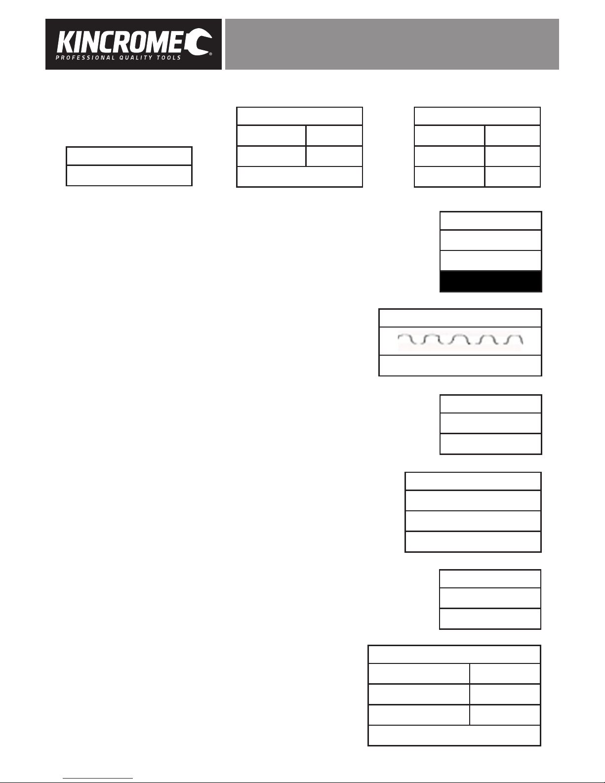
3. Press Up Key (1) / Down Key (2) to navigate to” 2. Battery in Vehicle” (Fig. 13)
and press Enter Key (4), it will enter “Test In Vehicle” menu (Fig. 14).
4. Choose one of the test as shown in Fig. 14 and press Enter Key (4).
B. Battery Test
The battery tester will test each battery according to the selected test standard
and rating.
1. Press Enter Key (4) on “1. Battery Test”, the “check surface charge” prompt
screen will display a sequence of instruction (Fig.15), which you are required
to follow before proceeding.
2. Once you have turned your headlights OFF, press the Enter Key (4).
C. Select Battery Type
1. The tester will prompt to select battery type (Fig. 16). Press Up Key (1) / Down
Key (2) to select battery type (as displayed on the battery rating label), then
press Enter Key (4) to confirm.
2. Press Up Key (1) / Down Key (2) to select the correct testing standard (Fig.17)
as specified on the battery rating label. Press Enter Key (4) to select testing
standard. Refer to the Battery System Standard Description page 13.
3. Press Up Key (1) / Down Key (2) to select the battery capacity rating
(Fig. 18) as displayed on the battery rating label. Press the Enter Key (4).
Note: A single Press Up Key (1) / Down Key (2) will increase / decrease by 5Amp
intervals, Press and hold Up Key (1) / Down Key (2) will increase /decrease
the rating rapidly.
4. The tester performs the test, It takes approximately 5-10 seconds to display
the battery test result.
5. Compare to the ‘Battery Test Result Examples’ on page 5.
6. Press the Exit Key (3) to return to the start-up screen.
D. Cranking Test
1. Connect tester as specified “Connecting the Tester” on Page 3.
2. Press Enter Key (4) to navigate to Main Menu.
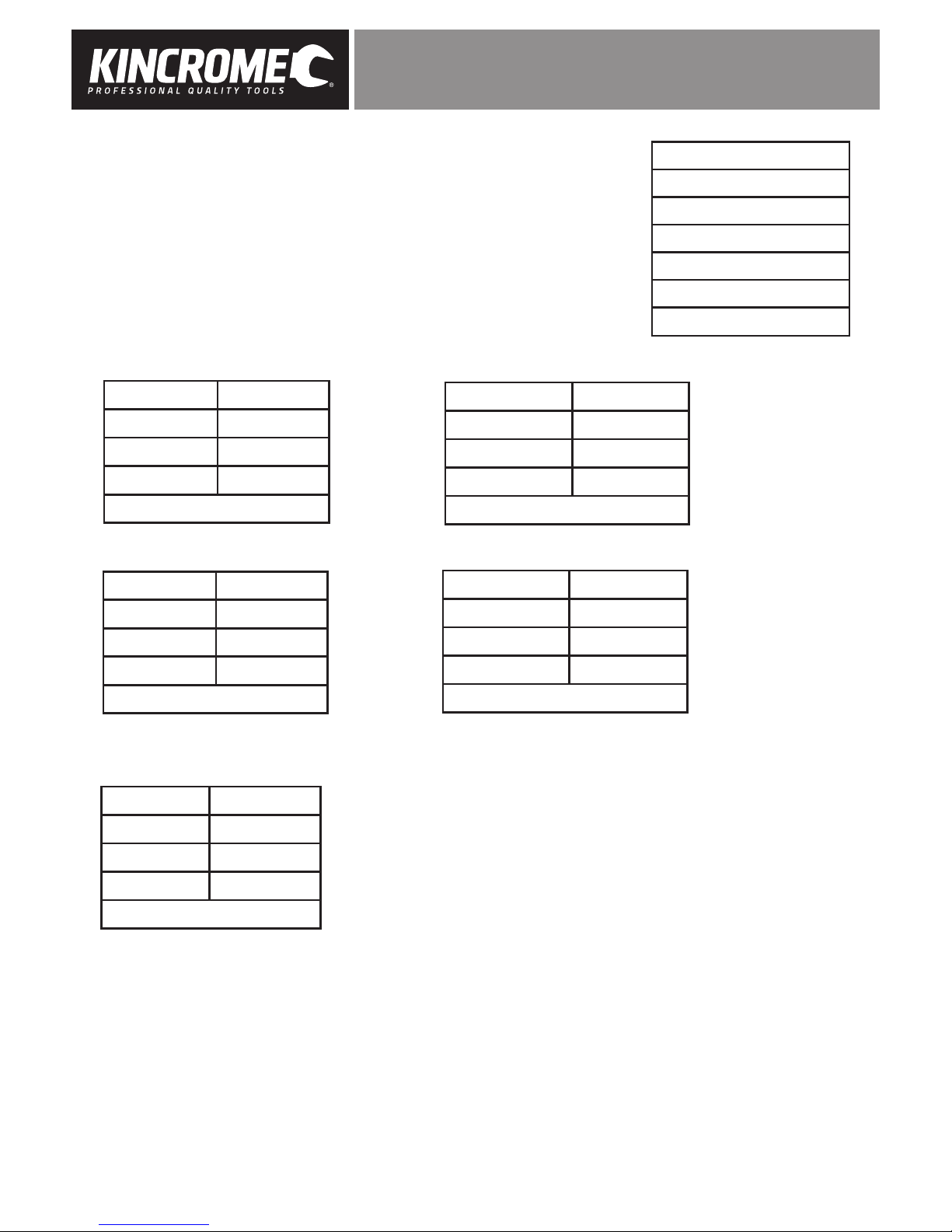
3. Press Up Key (1) / Down Key (2) to select the battery location, ” 2. Battery in
Vehicle” then press Enter Key (4) to confirm (Fig14).
4. “Start Engine” is prompted (Fig.19), Start the vehicle and the tester will
perform the cranking test and display the result (Fig 20, 21 & 22) on Page 7.
5. Normally a cranking voltage value lower than 9.6V is regarded as abnormal,
click the Enter Key (4).
6. Test result includes cranking voltage and cranking time.
7. After testing finished Press the Exit Key (3) to return to the start-up screen.
Note: If this is the last test, turn off vehicle engine.
Main Menu
1. Quick Test
2. Battery in Vehicle
3. Out of Vehicle
4. Review Data
5. Print Data
6. System Setup
Test In Vehicle
1. Battery Test
2. Cranking Test
3. Charging Test
Battery Test
1. Check surface charge.
Turn lights ON
2. Turn headlights on for
approx. 10 seconds
3. Turn lights OFF
Battery Type
1. Regular Flooded
2. AGM Flat Plate
3. AGM Spiral
4. GEL
5. EFB
Select Input
CCA
Setting Rating
500
CCA
Fig. 13
Fig. 14
Fig. 15
Fig. 16
Fig. 17
Fig. 18
Cranking Test
Start Engine
Fig. 19

BATTERY TESTER ANALYZER
7
Cranking Test Results
E. Charging Test
1. Connect tester as specified “Connecting the Tester”.
2. Press Enter Key (4) to navigate to Main Menu.
3. Press Up Key (1) / Down Key (2) to select “2. Battery in Vehicle”then press Enter Key
(4) to confirm.
4. Start the Vehicle’s engine.
5. Press Up Key (1) / Down Key (2) to select “3. Charging Test” (Fig. 23).
6. Press the Enter Key (4) to start the charging test.
Caution: Do not shut down the engine during the test. Ensure all electrical
accessories and devices remain in the OFF state. Turning ON/OFF any
electrical accessories in the vehicle during the test will affect the accuracy
of the test result.
Tester will do the following tests in a sequence:
1. For “Ripple Test”, tester will display the real time ripple and meanwhile, shows ripple
volt and charging volt values at the
bottom line (Fig. 24).
Note: It takes approx. 5-10 seconds to complete ripple test.
2. After the ripple test, tester will automatically start the Loaded Voltage Test
(Fig. 24). The tester prompts the Operator to “
Increase RPM to 2500r/min
and keep it 5 seconds
” (Fig 25), depress accelerator to increase engine revs.
3. Tester starts the Charging Volt Test, once the battery voltage is increase is
detected (Fig. 26).
4. After the test is finished, the tester will displays the test results and battery
charging state (No-Output, Charging Low, Charging Normal or Charging
High)(Fig. 28).
Note: The Tester will try 3 times to detect the Battery Voltage increase, if an increase
is not detected the tester will skip the rev detection test, and display the test result
from the ripple and loaded tests.
If the battery is not receiving a charge the tester displays “No Volt Output”.
Refer to Page 8 for explanation of charging states :
5. Press the Exit Key (3) to return to the start-up screen.
Cranking Test
RPM Detected
Cranking Test
Time 780ms
Cranking Normal
10.13V
Cranking Test
Time 1020ms
Cranking Low
Replace 10.13V
Charging Test
Loaded 14.16V
Unloaded 14.39V
Ripple 15mV
Charging Normal
Test in Vehicle
1. Battery Test
2. Cranking Test
3. Charging Test
Charging Test
Loaded Testing
*****
Charging Test
Testing
*****
Charging Test
Increase RPM to 2500 r/min
And keep it to 5 Seconds
Press ENTER to continue
Ripple Test
95mV 14.32V
Fig. 23
Fig. 24
Fig. 28
Fig. 25
Fig. 26
Fig. 27
Fig. 20 Fig. 21 Fig. 22

BATTERY TESTER ANALYZER
8
Charging Test Results
F. Out of Vehicle
1. Connect tester as specified in“Connecting the Tester” on Page 3.
2. Press Enter Key (4) to navigate to Main Menu.
3. Press Up Key (1) / Down Key (2) to navigate to “3. Out of Vehicle”, then press
Enter Key (4) to confirm (Fig. 29).
4. The tester will prompt to select battery type (Fig 30. Press Up Key (1) / Down
Key (2) to select battery type (as displayed on the battery rating label), then
press Enter Key (4) to confirm.
5. Press Up Key (1) / Down Key (2) to select the correct test standard (Fig.31) as
specified on the battery rating label. Press Enter Key (4) to select test standard.
Refer to the Battery System Standard Description page 13.
6. Press Up Key (1) / Down Key (2) to select the correct rated battery capacity
as displayed on the battery rating label. Press the Enter Key (4).
Note: A Single Press Up Key (1) / Down Key (2) will increase/decrease by 5Amp
intervals, Press and hold Up Key (1) / Down Key (2) will increases/Decrease
the rating rapidly.
7. The test is preformed, It takes approximately 5-10 seconds to display the
battery test result.
8. Refer to ‘Battery Test Result Examples’ on page 5 for battery condition.
9. Press the Exit Key (3) to return to the start-up screen.
Charging Volt
Normal • Charging system shows the alternator output is normal, no problem has been detected.
Low • Check if alternators’ drive belt is slipping or broken. Adjust or replace as required.
• Check the connections between alternator and battery to ensure there are no loose or
damaged connections. Tighten and replace as required.
• If both the drive belt and connections are in good condition, follow the vehicles’ manufacturer’s
troubleshooting to eliminate an alternator fault.
High • Most vehicle alternators use an internal regulator, the complete alternator assembly will be
required to be replaced (Some old cars use external regulator, which can be replaced).
• The acceptable high voltage limit of the regulator is a maximum of 14.7±0.5V.
If charging voltage is too high, it will overcharge the battery. The battery life maybe shortened.
No Volt Output • The RPM did not each 2500r/min.
• Check to see if the alternators’ drive belt is slipping or broken. Adjust or replace as required.
• Check the connections between alternator and battery to ensure there are NO loose or
damaged connections. Clean, tighten or replace as required.
• Alternator regulator fault, check and replace as required.
Diode Test • The Ripple Test will determine whether the diode(s) are functioning as designed.
When Ripple Test Voltage is too high, it indicates that at least one diode is damaged. Check and
replace any faulty diode(s).
Main Menu
1. Quick Test
2. Battery in Vehicle
3. Out of Vehicle
4. Review Data
5. Print Data
6. System Setup
Fig. 29
Setting Rating
500
CCA
Fig. 31
Battery Type
1. Regular Flooded.
2. AGM Flat Plate
3. AGM Spiral
4. GEL
5. EFB
Fig. 30

BATTERY TESTER ANALYZER
9
9. Review Data
1. Connect tester as specified “Connecting the Tester” on Page 3.
2. Press Enter Key (4) to navigate to Main Menu.
3. Press Up Key (1) / Down Key (2) to navigate to “4. Review Data” (Fig. 32).
Note: This will only display the last test performed
4. Refer to the below examples for battery conditions.
Main Menu
1. Quick Test
2. Battery in Vehicle
3. Out of Vehicle
4. Review Data
5. Print Data
6. System Setup
Fig. 32
Healthy: 96% 490CCA
Charge: 98% 12.64V
Internal R= 6.1m Ω
Rated: 500A
GOOD BATTERY
Healthy: 78% 490CCA
Charge: 30% 12.20V
Internal R= 7.2m Ω
Rated: 500A
GOOD, RECHARGE
Healthy: 46% 490CCA
Charge: 80% 12.68V
Internal R= 18.1m Ω
Rated: 500A
REPLACE
Healthy: 0% 0CCA
Charge: 20% 10.64V
Internal R= 45.2m Ω
Rated: 500A
BAD CELL, REPLACE
Healthy: 39% 310CCA
Charge: 20% 12.08V
Internal R= 30.1m Ω
Rated: 500A
CHARGE RETEST

BATTERY TESTER ANALYZER
10
10. Installing KP8501 Drivers
1. Insert the CD supplied with the tester and when the Autoplay select “Open folder to view files” (Fig 32).
2. Double click on Software and USB driver folder (Fig. 33)
3. Double Click “Battery Tester” Folder (Fig. 34)
4. Double Click the “KP8501 Battery Tester” Folder (Fig. 35)
5. Double Click the USB Driver Folder (Fig.36)
6. Double Click the installation file and follow the prompts..
11. Print Data
1. Navigate into “KP8501 Battery Tester Folder” (Fig.35) as described in “Installing KP8501 Drivers”
2. Double Click Print Software folder (Fig 36).
3. Double Click “PrintCOM” application.
Note: This program can run from the CD, or copied to your local computer hard drive.
4. Before proceeding any further, press the clear button to remove any information displayed (Fig 32).
5. Using the USB to USB-Mini cable (supplied) connect the tester to your computer.
6. When the tester is connected, the software should automatically detect the tester COM port No, if not select
COM port manually.
7. Press Enter Key (4) to navigate to Main Menu.
8. Press Up Key (1) / Down Key (2) to navigate to “5. Print Data” (Fig. 33) and press Enter Key (4) to export
the data.
Note: The tester will return to the Main Menu (Fig. 33) after export is completed.
9. Once the data is transferred to the computer, the print software will show testing results (Fig. 34).
10. In the Print COM program click the print button and follow your computer printing procedure.
Fig. 33 Fig. 34
Fig. 36Fig. 35
Fig. 32
Fig. 32 Fig. 33 Fig. 34
Main Menu
1. Quick Test
2. Battery in Vehicle
3. Out of Vehicle
4. Review Data
5. Print Data
6. System Setup

BATTERY TESTER ANALYZER
11
12. Battery System Standard Description
1. The battery tester analyzer will test each battery according to the selected system and rating.
13. Measuring Range
The Battery Tester can perform test on batteries rated within 100-2000CCA/30Ah-220AH
Measure Standard Measure Range
CCA 100-2000
BCI 100-2000
CA 100-2000
MCA 100-2000
JIS 26A17--245H52
DIN 100-1400
IEC 100-1400
EN 100-2000
SAE 100-2000
GB 100-1400
CCA Cold Cranking Amps, specified by SAE&BCI, most frequently used value for starting battery at 0°F
(-18°C)
BCI Battery Council International standard
CA Cranking Amps standard, effective starting current value at 0°C
MCA Marine Cranking Amps standard, effective starting current value at 0°C.
JIS Japan Industrial Standard, displayed on the battery as combination of the numbers and letters, e.g.
55D23,80D26.
DIN German Auto Industry Committee Standard
IEC Internal Electro technical Commission Standard
EN European Automobile Industry Association Standard
SAE Society of Automotive Engineers Standard
GB China National Standard

BATTERY TESTER ANALYZER
12
Spare Parts
No spare parts are available for this product. Contact Kincrome Customer Service for information regarding spares /
replacement of this product.
Office Contact Details
Phone: 1300 657 528
Fax: 1300 556 005
Email: enquiries@kincrome.com.au
Website: www.kincrome.com.au
Caring For The Environment
When a tool is no longer usable it should not be disposed of with household waste, but in an environmentally
friendly way. Please recycle where facilities exist. Check with your local council authority for recycling advice.
Recycling packaging reduces the need for landfill and raw materials. Reuse of recycled material decreases
pollution in the environment. Please recycle packaging where facilities exist. Check with your local council authority for
recycling advice.
Also Available
Battery Load Tester - 6 or 12V <100A
• Test 6V or 12V batteries, test the charging system, analyze battery condition,
test starter motor on your vehicle all with one tool
• Test standard lead acid vehicle batteries
KP1460
Carbon Pile Load Tester - 12V <500A
• Test 12V DC batteries, alternators, regulators & starters
• Test batteries up to 160Ah/1000CCA
• 500 Amp adjustable load
• Large colour coded display meters
• Metal, powder coated surface
KP1461
Diagnostic Scan Tool OBD2 - CAN Enabled
• Works with MOST 1996 and later OBD2 compliant vehicles
• Supports all OBD2 protocols including the newer (CAN) Controller Area Network
• Reads your (DTC) Diagnostic Trouble Codes for identification
• Turns off check engine light (MIL)
• Erases (DTC) trouble codes and resets the OBD2 system
• Includes a user manual with a comprehensive list of the most current trouble codes
K8410

BATTERY TESTER ANALYZER
13
Also Available Cont.
Booster Cables
Standard 100A 12V DC
• Suits 4 Cylinder Petrol Engines •2.5m Cable Length
• Heavy Duty Terminal Clamps
KP1451
Standard 200A 12V DC
• Suits 4, 6 Cylinder Petrol Engines •2.5m Cable Length
• Heavy Duty Terminal Clamps
KP1452
Premium 400A 12V / 24V DC
• Suits 4, 6 & 8 Cylinder Petrol Engines •3m Cable Length
• Heavy Duty Terminal Clamps • Intelli Check II Feature
KP1453
Premium 600A 12V / 24V DC
• Suits Diesel & Petrol Engines •3.5m Cable Length
• Extra Heavy Duty Terminal Clamps • Intelli Check II Feature
• Copper Clamp Bridges
KP1454
Ultimate 800A 12V / 24V DC
• Suits Commercial Vehicles •3.5m Cable Length
• Extra Heavy Duty Terminal Clamps • Intelli Check II Feature
• Copper Clamp Bridges
KP1455
Ultimate 1000A 12V / 24V DC
• Suits Construction & Earth Moving •6m Cable Length
• Extra Heavy Duty Terminal Clamps • Intelli Check II Feature
• Copper Clamp Bridges
KP1456
INTELLI-CHECK II
Alternator Check
Reverse Polarity Indicator
Battery Condition Indicator
KP1453, KP1454,
KP1455 & KP1456
Include

BATTERY TESTER ANALYZER
14
Warranty given by Kincrome Australia Pty Ltd of 3 Lakeview Drive, Caribbean Park, Scoresby, Victoria (Tel 1300 657 528). The applicable
warranty period (12 months) commences on the date that the product is purchased. If this product has materials or workmanship defects
(other than defects caused by abnormal or non warranted use) you can, at your cost, send the product to place of purchase, an authorised
Kincrome service agent or one of Kincromes addresses for repair or replacement. Your rights under this warranty are in addition to any other
rights you have under the Australian Consumer Law or other applicable laws. Our goods come with guarantees that cannot be excluded under
the Australian Consumer Law. You are entitled to a replacement or refund for a major failure and compensation for any other reasonably
foreseeable loss or damage. You are also entitled to have the goods repaired or replaced if the goods fail to be of acceptable quality and the
failure does not amount to a major failure. For further details please visit www.kincrome.com.au or call us. Due to minor changes in design or
manufacture, the product you purchase may sometimes differ from the one shown on the packaging.
Notes
G
U
A
R
A
N
T
E
E

www.kincrome.com.au
Table of contents
Other kincrome Test Equipment manuals
Popular Test Equipment manuals by other brands

Tektronix
Tektronix 2337 instruction manual

Huazheng
Huazheng HZJY-15K manual

Apera Instruments
Apera Instruments Premium Series user manual

Agilent Technologies
Agilent Technologies Infiniium 80000 Series Service guide

MSG Equipment
MSG Equipment MS016 user manual

Agilent Technologies
Agilent Technologies 5530 reference guide

HCD
HCD BW-KC1 quick start guide

Radiodetection
Radiodetection RD7100 user guide

Inficon
Inficon Quantus LP100 operating manual

Kyoritsu Electrical Instruments Works, Ltd.
Kyoritsu Electrical Instruments Works, Ltd. 4200 instruction manual

Apera Instruments
Apera Instruments GroStar GS1 user guide

Distek
Distek Premiere 5100 Operation manual