Allied Radio Knight-Kit KG-620 VTVM User manual

copyright
1956,
1963
Knight
Brectronght
Core.,
Mayivood.
iHinois
4
a

Thank
You.
..
for
your
interest
in
Knight-Kits.
This
Assembly
Manual
represents
our
many
decades
of
ex-
perience
in
developing
electronic
kits
which
bring
you
out-
standing
performance
at
dollar-saving
prices...
and
with
maximum
ease
of
construction.
As
you
go
through
the
pages
of
this
brochure,
note
how
carefully
each
stage
of
construction
is
explained—how
each
diagram
is
magnified
so
that
you
almost
have
the
feeling
a
good
instructor
is
working
at
your
side!
Knight-Kit’s
‘do
and
check’’
method
of
kit-building
insures
accurate
and
simple
assembly.
Although
your
final
product
may
represent
a
very
complicated
piece
of
electronic
equipment,
you
will
proceed
with
ease
and
assurance,
step-by-step...
and
enjoy
enormous
satisfaction
in
your
completed
working
unit.
Every
Knight-Kit
of
your
choice
is
available
to
you
on
the
Allied
Credit
Fund
Plan—
«
No
Money
Down
«24
Months
To
Pay
«Up
To
50%
Increased
Buying
Power
Your
Knight-Kit
purchase
is
backed
with
our
exclusive
and
iron-clad
guarantee—you
must
be
completely
satisfied
or
your
purchase
price
is
refunded!
It
is
always
a
pleasure
to
serve
you.
A.
D.
Davis,
President
ELECTRONIC
VACUUM
TUBE
VOLTMETER
KIT
FEATURES
*
Push-Pull
Balanced-Bridge
Meter
Circuit
+»
Positive
and
Negative
DC
Function
Assures
Accuracy
and
Protection
Switch
Positions
Eliminate
Lead
Reversal
*
Zero-Center
Scale
for
Alignment
of
TV
and
FM
Discriminator
Circuits
*
Measures
BOTH
Peak-to-Peak
and
RMS,
Transformer-Type
Power
Supply
for
Line
*
11-Megohm
Input
Resistance
Minimizes
Circuit
Loading—Gives
True
Readings
AC
Voltages
in
7
Ranges
Each
isolation
and
Operating
Safety
*
Single
Zero-Adjustment
Control
for
all
+
Calibrates
Without
Removing
Cabinet
Functions
and
all
Ranges
«
Film-Type
1%
Precision
Resistors
Outstanding
in
both
performance
and
value.
...
offering
all
the
quality
that
years
of
experience
and
research
in
instrument
development
can
provide
...
having
all
the
modern,
advanced
features
needed
for
all-around
efficiency
of
electronics
servicing
...
this
is
your
Knight-Kit
VTVM.
Provides
entirely
electronic,
direct-reading
measurement
of
AC
voltage
(BOTH
Peak-to-Peak
and
RMS
values),
DC
voltage,
decibels
and
resistance
on
a
rugged,
highly
legible,
two-color
44%”
full-view
meter.
Invaluable
for
signal
tracing,
for
alignment,
for
voltage
and
resistance
measurements
in
AM/FM
radios
or
tuners,
television
and
hi-fi
sets,
for
checking
frequency
response,
for
continuity
tests,
and
for
servicing
electrical
equipment.
Feature
highlights
include:
film-type
1%
precision
resistors
and
multipliers;
low-leakage
function
and
range
switches;
finest-grade
printed
circuit
board;
3
separate
test
leads
for
AC-Ohms,
DC,
and
Common;
heavy-gauge
steel
case
with
rugged
panel:
pilot
light:
transformer-operated
power
supply
for
line
isolation
and
safety;
standard
1%-volt
‘‘C’’
battery;
200-microamp
meter
move-
ment;
carrying
strap;
and
premium-quality
parts,
Circuitry
boasts:
push-pull
balanced-bridge
for
maximum
accuracy
and
meter
protection;
DC
polarity-reversing
switching;
11-megohm
input
resistance
to
reduce
circuit
loading
to
a
minimum
and
assure
true
readings;
zero-center
scale;
direct-reading
decibel
scale;
highly
sensitive
DC
amplifier
to
allow
resistance
measurements
as
high
as
1000
megohms
using
only
the
1%
volt
battery
—
eliminating
danger
to
delicate
apparatus
under
test;
single
zero-
adjustment
control
for
all
functions
and
ranges;
and
calibration
without
removing
internal
chassis
from
cabinet.
Always
look
to
Knight-Kit,
established
leader
in
professional
test
equipment
design,
for
versatility,
rugged
construction,
and
proven
dependability.

SPECIFICATIONS
DC
Voltmeter:
RangeS..........00...000
cee
1.5,
5,
15, 50,
150,
500,
and
1500
volts
full
scale.
Input
Resistance..............
11
Megohms
(1
Megohm
in
probe)
on
all
ranges.
Circult:.
3:4.
gh
akon
Push-
Pull
balanced
bridge with
12AU7
twin
triode.
ACCULACY......
cece
eee
+3%
full
scale.
AC
Voltmeter:
RMS
Ranges...................
1.5,
5,
15,
50,
150,
500,
1500
volts
full
scale.
ACCULACY...0..
eee
+5%
full
scale.
Peak-to-Peak
Ranges......4,
14, 40,
140,
400,
1400,
4000
volts.
Ohmmeter:
Ranges...
i.2c.ocacc
eave:
Center
scale
at
10
with
multipliers
X
1,
x
10,
x
100,
x
1000,
x
10K,
*
100K,
x
1Meg.
Meter:
414”
200
»A
movement.
Multipliers:
1%
precision
type.
12AU7,
twin
triode
me-
ter
bridge.
6AL5,
twin
diode
full
wave
rectifier.
Tube
Complement:
110-125
volts,
60
cycles
AC,
Power
Supply:
Battery:
1.5
volt
“C”
battery.
HOW
TO
BUILD
THE
KNIGHT
VTVM
Your
KNIGHT
VTVM
uses
a
printed
circuit
which
assures
you
that
the
VTVM
will
be
an
accurate,
reli-
able
test
instrument
regardless
of
age.
A
sheet
of
cop-
per
is
bonded
to
a
sheet
of
phenolic.
When
the
wiring
pattern
has
been
determined,
the
unused
portion
of
the
copper
sheet
is
etched
off
leaving
an
exact
dupli-
cation
of
the
engineering
prototype.
Exact
duplication
is
one
of
the
greatest
advantages
of
printed
circuits,
and
prevents
variation
in
wiring
and
performance
from
instrument
to
instrument.
Your
KNIGHT
VTVM
is
all
electronic.
That
is,
the
bridge
circuit
is
used
for
every
measurement
of
DC
2
voltage,
resistance,
and
AC
voltage
after
rectification
by
the
full-wave
rectifier.
The
meter
employed
is
an
extremely
stable,
sensitive
200
microampere
movement.
The
multipliers
are
1%
precision
type.
Overall
accuracy
of
the
DC
functions
is
+3%
of
full
scale
reading,
and
+-5%
on
AC
functions.
A
wide
choice
of
measurements
is
provided
giving
you
seven
ranges
on
DC,
AC,
and
resistance.
Both
RMS
and
peak-to-peak
AC
voltages
may
be
measured.
Your
KNIGHT
VTVM,
through
the
use
of
the
print-
ed
circuit,
saves
a
great
deal
of
tedious
wiring,
assures
you
of
a
finished
instrument
which
compares
closely
to
the
original
engineering
model,
and
provides
you
with
an
instrument
worth
many
times
its
low
cost.
Before
starting
to
build
your
KNIGHT
VTVM,
check
each
part
against
the
Parts
List
on
page
23.
If
you
are
unable
to
identify
some
of
the
parts
by
sight,
locate
them
on
the
pictorial
diagrams.
Capacitor
and
resistor
values,
if
not
printed
on
the
part,
can
be
found
with
the
aid
of
the
color
code
chart.
Hardware
is
listed
in
the
last
part
of
the
Parts
List.
To
keep
our
kits
at
the
lowest
possible
price,
we
fre-
quently
weigh
hardware
rather
than
to
count
it.
Therefore,
do
not
be
concerned
if
more
nuts
and
machine
screws,
for
example,
are
supplied
than
are
specified
in
the
Parts
List.
The
only
tools
required
for
building
your
KNIGHT
VTVM
are:
Long-nose
pliers,
diagonal
cutters,
screw-
driver,
set-screw
driver,
and
a
soldering
iron.
Study
the
pictorial
diagrams
and
note
how
the
parts
are
mounted.
These
pictorial
diagrams
show
the
actual
location
of
all
parts
and
wiring.
The
schematic
dia-
gram
shows
how
the
parts
are
connected
electrically
and
is
helpful
in
understanding
how
the
circuits
work.
The
step-by-step
instructions
were
prepared
by
a
skilled
technician
while
he
was
actually
building
the
KNIGHT
VTVM.
Therefore,
they
are
the
best
and
fastest
way
of
assembling
this
instrument.
We
suggest
that
you
read
through
the
instructions
before
building
the
VTVM.
This
will
enable
you
to
familiarize
yourself
with
the
procedure
and
avoid
possible
errors.
We
invite
you
to
use
the
blank
parentheses,
(
),
before
each
step
to
check
it
off
after
you
have
completed
it.
Each
step
is
clearly
illustrated
on
an
accompanying
line
drawing.
Some
builders
prefer
to
“cross
out”
each
wire
and
component
on
the
drawings
with
a
colored
pencil
after
it
is
installed.
While
an
excellent
way
to
avoid
mistakes,
and
highly
recommended
by
us,
this
procedure
results
in
drawings
that
are
difficult
to
re-
use.
For
this
reason
each
wiring
view
is
reproduced
on
a
separate,
folded
sheet
of
paper.
You
are
now
ready
to
build
your
KNIGHT
VTVM.
THIS
KIT
MUST
BE
PROPERLY
SOLDERED!
USE
ENOUGH
HEAT
This
is
the
main
idea
of
good
soldering.
Apply
enough
heat
to
the
metal
surfaces
you
are
joining
to
make
the
solder
spread
freely,
until
the
contour
(shape)
of
the
connection
shows
under
the
solder.
AN
ELECTRONIC
UNIT
WILL
NOT
WORK...
unless
it
is
properly
soldered.
Read
these
instructions
carefully
to
understand
the
basic
ideas
of
good
soldering.
Enough
heat
must
be
used
so
the
solder
can
actually
pene-
trate
the
metal
surfaces,
making
an
unbroken
path
over
which
electricity
can
travel.
You
are
not
using
enough
heat
if
the
solder
barely
melts
and
forms
a
rounded
ball
of
rough,
flaky
solder.
Use
the
Right
Soldering
Tool
A
soldering
iron
in
the
40-100
watt
range
is
recommended.
Any
iron
in
this
range
with
a
clean,
chisel-shaped
tip
will
supply
the
correct
amount
of
heat
to
make
a
good
solder
connection.
You
may
also
use
a
solder
gun
but
make
sure
the
tip
reaches
full
heat
before
you
solder.
Keep
the
iron
or
gun
tip
brightly
coated
with
solder,
When
necessary,
wipe
the
hot
tip
clean
with
a
cloth.
If
you
are
using
an
old
tip,
clean
it
before
you
start
soldering.
Use
a
fine
file
or
steel
wool
to
expose
the
bright
metal.
Heat
the
iron
and
immediately
coat
the
tip
with
solder.
Use
Only
Rosin
Core
Solder
We
supply
the
right
kind
of
solder
(rosin
core
solder).
Do
not
use
any
other
kind
of
solder!
Use
of
Acid
Core
Solder,
Paste,
or
lrons
Cleaned
on
a
Sal
Ammoniac
Block
will
ruin
any
Electronic
Unit
and
will
Void
the
Guarantee.
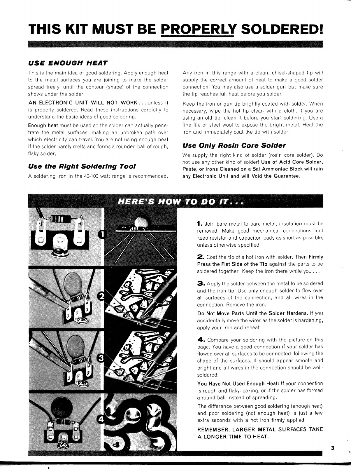
1.
Join
bare
metal
to
bare
metal;
insulation
must
be
removed.
Make
good
mechanical
connections
and
keep
resistor
and
capacitor
leads
as
short
as
possible,
unless
otherwise
specified.
2.
Coat
the
tip
of
a
hot
iron
with
solder.
Then
Firmly
Press
the
Flat
Side
of
the
Tip
against
the
parts
to
be
soldered
together.
Keep
the
iron
there
while
you...
3.
Apply
the
solder
between
the
metal
to
be
soldered
and
the
iron
tip.
Use
only
enough
solder
to
flow
over
all
surfaces
of
the
connection,
and
all
wires
in
the
connection.
Remove
the
iron.
Do
Not
Move
Parts
Until
the
Solder
Hardens.
If
you
accidentally
move
the
wires
as
the
solder
is
hardening,
apply
your
iron
and
reheat.
4..
Compare
your
soldering
with
the
picture
on
this
page.
You
have
a
good
connection
if
your
solder
has
flowed
over
all
surfaces
to
be
connected
following
the
shape
of
the
surfaces.
It
should
appear
smooth
and
bright
and
all
wires
in
the
connection
should
be
well-
soldered,
You
Have
Not
Used
Enough
Heat:
If
your
connection
is
rough
and
flaky-looking,
or
if
the
solder
has
formed
a
round
ball
instead
of
spreading.
The
difference
between
good
soldering
(enough
heat)
and
poor
soldering
(not
enough
heat)
is
just
a
few
extra
seconds
with
a
hot
iron
firmly
applied.
REMEMBER,
LARGER
METAL
SURFACES
TAKE
A
LONGER
TIME
TO
HEAT.
SHOULDER
PIN
JACK
So
WASHER
PIN
JACK
DETAIL
SCRAPE
PAINT
AWAY
FROM
HOLE
SCRAPE
PAINT
AWAY
FROM
HOLE
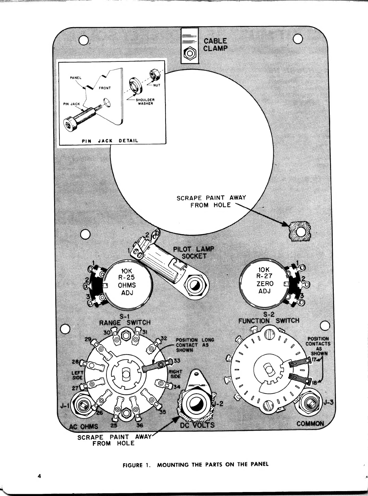
FIGURE
1.
MOUNTING
THE
PARTS
ON
THE
PANEL
:

MOUNTING
THE
PARTS
ON
THE
PANEL
Before
you
begin
mounting
the
parts,
place
a
pad
or
a
soft
cloth
on
your
work
table
to
protect
the
finish
on
the
front
panel.
SEE
FIGURES
1
AND
2
(
)
Insert
the
short
flat
head
screw
through
the
hole
in
the
top
center
of
the
panel.
Place
an
external
lockwasher
over
the
screw.
Next
put
one
of
the
cable
clamps
over
the
screw.
Now,
put
on
an
in-
ternal
lockwasher
and
tighten
a
nut
over
it
very
securely.
See
Figure
2.
Bw
|
'
'
INTERNAL
LOCKWASHER
GQ
|
'CABINET
MOUNTING
CLIP
Sere
CLAMP)
!
EXTERNAL
LOCKWASHER
FIGURE
2.
HOW
TO
ASSEMBLE
THE
CABINET
CLAMP
( )
Mount
R-25,
10K
ohms
OHMS
ADJUST
potenti-
ometer,
in
the
large
hole
in
the
left
center
of
the
panel.
Use
two
nuts
to
mount
this
control
as
shown
in
Figure
3.
MOUNTING
/
HOLES.
~%
SHE
=
$y)
))
4
controg
»
CONTREL
HEX
NUTS
(2)
FIGURE
3.
HOW
TO
MOUNT
A
CONTROL
(
)
Mount
R-27,
10K
ohm
ZERO
ADJUST
potenti-
ometer,
in
the
large
hole
in
the
right
center
of
the
panel,
in
the
same
manner.
(
)
Mount
the
‘pilot
light
socket
between
R-25
and
R-27.
The
bracket
must
be
positioned
as
shown
in
Figure
1,
but
must
not
touch
R-25.
(
)
Mount
J-1,
the
red
pin
jack,
in
the
lower
left
corner
of
the
panel.
Use
a
shouldered
fiber
washer
on
the
inside
of
the
panel
to
insulate
the
jack
from
the
panel.
Now,
tighten
a
nut
against
the
washer.
Refer
to
the
pin
jack
detail
in
the
upper
left
corner
of
Figure
1.
(
)
Mount
J-3,
the
black
pin
jack,
in
the
lower
right
corner
of
the
panel
in
the
same
manner.
(
)
Scrape
the
paint
from
the
two
holes
as
shown.
(
)
Mount
J-2,
the
chassis
connector
in
the
large
hole
in
the
lower
center
of
the
panel.
This
con-
nector
is
supplied
with
a
shouldered
fiber
wash-
er.
Take
this
washer
off
and
throw
it
away.
Place
the
flat
fiber
washer
over
the
small
threaded
end
of
the
connector.
Scrape
the
paint
from
around
this
hole
on
the
rear
of
the
panel.
Insert
the
small
threaded
end
through
the
hole
in
the
panel.
Place
the
solder
lug
and
the
flat
metal
washer
on
the
connector
and
tighten
the
nut
securely.
See
Figure
4.
SOLDER
LUG
FLAT
FIBER
WASHER
WASHER
FIGURE
4.
HOW
TO
MOUNT
THE
CHASSIS
CONNECTOR
( )
Mount
S§-1,
the
long
triple
wafer
RANGE
switch
in
the
hole
in
the
lower
left
corner
of
the
panel.
The
long
contact
on
the
end
wafer
must
be
posi-
tioned
as
shown
in
Figure
1.
The
blank
space
on
the
wafer
near
the
shaft
end
must
be
toward
J-1.
Use
a
large
nut
and
a
lockwasher
on
the
inside
of
the
panel.
Fasten
it
securely
with
another
large
nut.
Place
a
large
knob
on
the
shaft.
Be
sure
the
line
on
the
knob
lines
up
ex-
actly
with
the
printed
dots
on
the
panel.
If
not,
rotate
S-1
so
the
scale
on
the
panel
and
the
line
on
the
knob
correspond.
( )
Mount
S-2,
the
other
triple
wafer
FUNCTION
switch,
in
the
other
hole
on
the
right
of
the
panel.
Use
another
large
nut
and
lockwasher
in-
side
the
panel.
Use
a
large
nut
outside
the
panel.
Again
place
a
knob
on
the
shaft
and
be
sure
that
the
line
on
the
knob
lines
up
with
the
scale
on
the
panel.
You
have
finished
mounting
the
parts
on
the
panel
until
after
the
switches
are
wired.
WIRING
AND
SOLDERING
HINTS
How
well
a
piece
of
electronic
equipment
works
of-
ten
depends
on
the
quality
of
workmanship
used
in
its
construction.
It
is
for
this
reason
that
the
following
suggestions
are
made.
These
hints
are
mainly
for
the
beginner,
however,
even
experienced
persons
may
benefit
from
a
brief
review.
The
insulated
wire
furnished
with
this
kit
is
cut
to
length
and
the
ends
are
stripped.
Each
different
col-
ored
wire
is
a
different
length,
therefore,
be
sure
to
use
the
color
specified
in
each
of
the
wiring
steps.
A
long
piece
of
bare
wire
is
included.
Whenever
it
is
necessary
to
use
some
of
it,
the
exact
length
of
the
piece
required
is
given.
The
flexible
tubing
supplied
is
called
“spaghetti”.
Spaghetti
is
used
to
cover
the
bare
end
leads
of
some
of
the
components
and
portions
of
some
of
the
bare
wires
when
there
is
danger
they
will
touch
other
bare
wires
or
the
chassis.
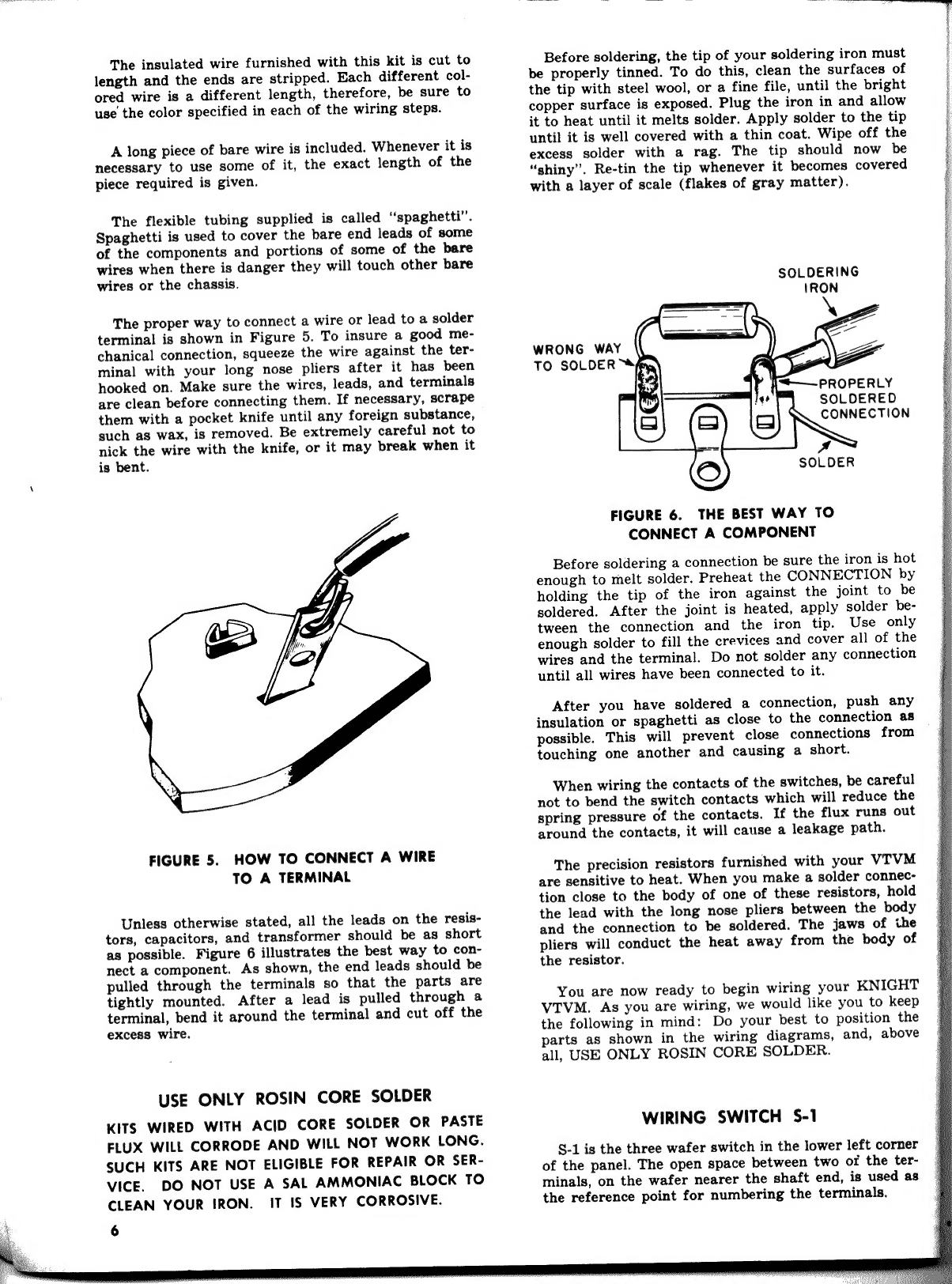
The
proper
way
to
connect
a
wire
or
lead
to
a
solder
terminal
is
shown
in
Figure
5.
To
insure
a
good
me-
chanical
connection,
squeeze
the
wire
against
the
ter-
minal
with
your
long
nose
pliers
after
it
has
been
hooked
on.
Make
sure
the
wires,
leads,
and
terminals
are
clean
before
connecting
them.
If
necessary,
scrape
them
with
a
pocket
knife
until
any
foreign
substance,
such
as
wax,
is
removed.
Be
extremely
careful
not
to
nick
the
wire
with
the
knife,
or
it
may
break
when
it
is
bent.
FIGURE
5.
HOW
TO
CONNECT
A
WIRE
TO
A
TERMINAL
Unless
otherwise
stated,
all
the
leads
on
the
resis-
tors,
capacitors,
and
transformer
should
be
as
short
as
possible.
Figure
6
illustrates
the
best
way
to
con-
nect
a
component.
As
shown,
the
end
leads
should
be
pulled
through
the
terminals
so
that
the
parts
are
tightly
mounted.
After
a
lead
is
pulled
through
a
terminal,
bend
it
around
the
terminal
and
cut
off
the
excess
wire.
USE
ONLY
ROSIN
CORE
SOLDER
KITS
WIRED
WITH
ACID
CORE
SOLDER
OR
PASTE
FLUX
WILL
CORRODE
AND
WILL
NOT
WORK
LONG.
SUCH
KITS
ARE
NOT
ELIGIBLE
FOR
REPAIR
OR
SER-
VICE.
DO
NOT
USE
A
SAL
AMMONIAC
BLOCK
TO
CLEAN
YOUR
IRON.
IT
IS
VERY
CORROSIVE.
6
Before
soldering,
the
tip
of
your
soldering
iron
must
be
properly
tinned.
To
do
this,
clean
the
surfaces
of
the
tip
with
steel
wool,
or
a
fine
file,
until
the
bright
copper
surface
is
exposed.
Plug
the
iron
in
and
allow
it
to
heat
until
it
melts
solder.
Apply
solder
to
the
tip
until
it
is
well
covered
with
a
thin
coat.
Wipe
off
the
excess
solder
with
a
rag.
The
tip
should
now
be
“shiny”.
Re-tin
the
tip
whenever
it
becomes
covered
with
a
layer
of
scale
(flakes
of
gray
matter).
SOLDERING
WRONG
WAY
TO
SOLDER
“fey,
}“t+——~-
PROPERLY
SOLDERED
Roeten
A
SOLDER
FIGURE
6.
THE
BEST
WAY
TO
CONNECT
A
COMPONENT
Before
soldering
a
connection
be
sure
the
iron
is
hot
enough
to
melt
solder.
Preheat
the
CONNECTION
by
holding
the
tip
of
the
iron
against
the
joint
to
be
soldered.
After
the
joint
is
heated,
apply
solder
be-
tween
the
connection
and
the
iron
tip.
Use
only
enough
solder
to
fill
the
crevices
and
cover
all
of
the
wires
and
the
terminal.
Do
not
solder
any
connection
until
all
wires
have
been
connected
to
it.
After
you
have
soldered
a
connection,
push
any
insulation
or
spaghetti
as
close
to
the
connection
as
possible.
This
will
prevent
close
connections
from
touching
one
another
and
causing
a
short.
When
wiring
the
contacts
of
the
switches,
be
careful
not
to
bend
the
switch
contacts
which
will
reduce
the
spring
pressure
of
the
contacts.
If
the
flux
runs
out
around
the
contacts,
it
will
cause
a
leakage
path.
The
precision
resistors
furnished
with
your
VTVM
are
sensitive
to
heat.
When
you
make
a
solder
connec-
tion
close
to
the
body
of
one
of
these
resistors,
hold
the
lead
with
the
long
nose
pliers
between
the
body
and
the
connection
to
be
soldered.
The
jaws
of
the
pliers
will
conduct
the
heat
away
from
the
body
of
the
resistor.
You
are
now
ready
to
begin
wiring
your
KNIGHT
VTVM.
As
you
are
wiring,
we
would
like
you
to
keep
the
following
in
mind:
Do
your
best
to
position
the
parts
as
shown
in
the
wiring
diagrams,
and,
above
all,
USE
ONLY
ROSIN
CORE
SOLDER.
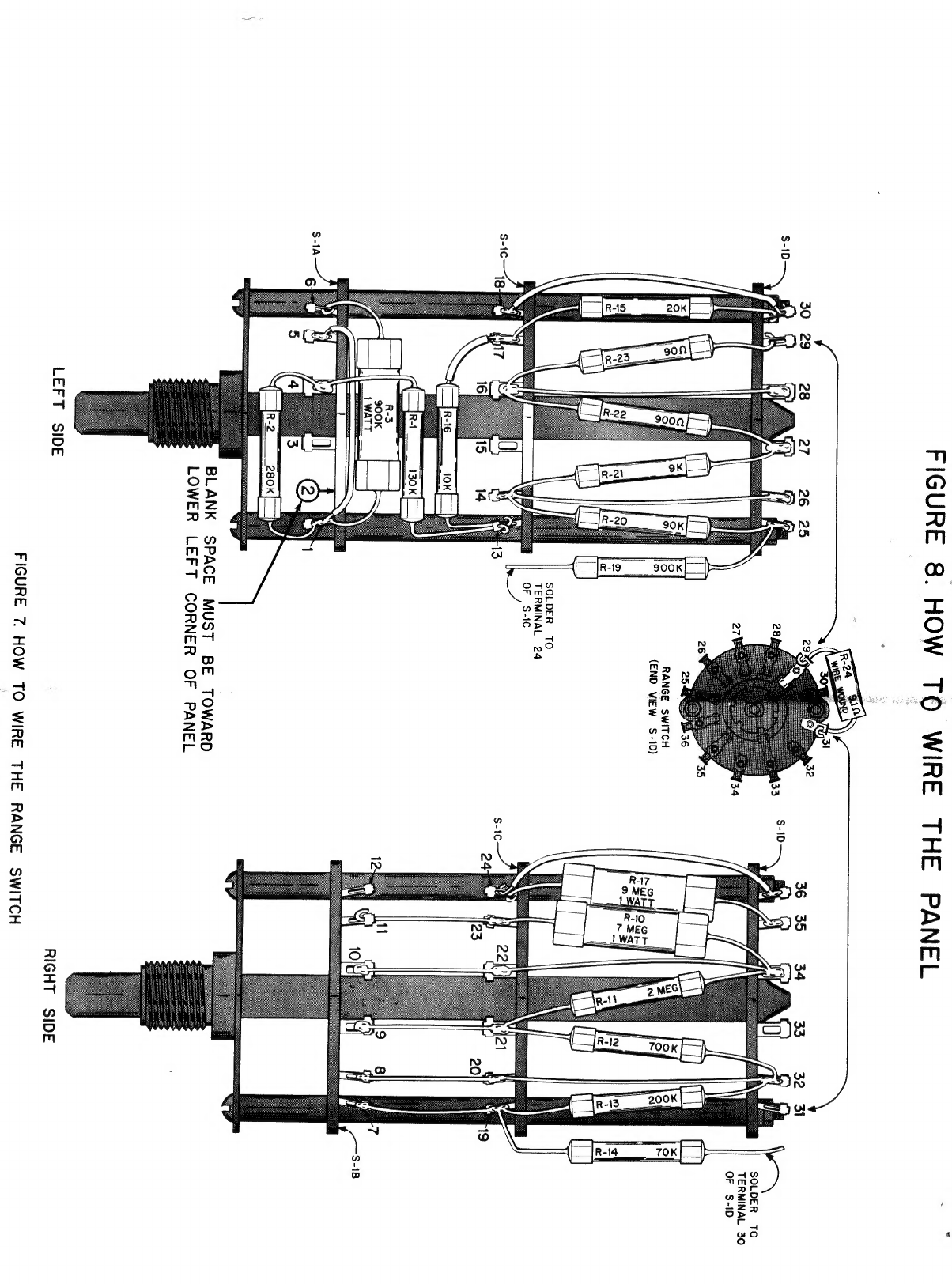
WIRING
SWITCH
S-1
§-1
is
the
three
wafer
switch
in
the
lower
left
corner
of
the
panel.
The
open
space
between
two
of
the
ter-
minals,
on
the
wafer
nearer
the
shaft
end,
is
used
as
the
reference
point
for
numbering
the
terminals.

SEE
FIGURE
7.
(
)
Connect,
but
do
not
solder,
one
end
of
R-16,
10K
ohm
resistor,
to
terminal
13.
Insert
the
other
CAUTION:
The
precision
resistors
mounted
on
the
end
through
a
1%
inch
length
of
spaghetti.
Con-
range
switch
S-1
must
not
touch
each
other,
nearby
nect,
but
do
not
solder,
it
to
terminal
17.
ee
a
the
a
nie
ae
alone
utes
( )
Connect,
but
do
not
solder,
one
end
of
R-20,
90K
ee
ae
dl
s
Pars
He
pita
a
a
Uae
Rent
ie
anes
ohm
resistor,
to
terminal
14.
Connect,
but
do
aeauansas
“pail
Seeacsee
age
A
Se
Re
eee
not
solder,
the
other
end
to
terminal
25.
resistors,
keep
the
leads
short,
as
shown
in
the
illus-
tration.
Clip
off
excess
lead
lengths.
( )
Connect,
but
do
not
solder,
one
end
of
a
2
inch
( )
Connect,
but
do
not
solder,
one
end
of
R-2,
280K
esata
a
Denne.
14.
Solder
the
other
end
ohm
resistor,
to
terminal
1
of
S-1.
Connect,
but
5
do
not
solder,
the
other
end
to
terminal
4
of
S-1.
(
)
Solder
one
end
of
R-21,
9K
ohm
resistor
to
ter-
Position
R-2
as
shown
in
Figure
7.
minal
14.
Connect,
but
do
not
solder,
the
other
(
)
Connect,
but
do
not
solder,
one
end
of
R-3,
900K
end
to
terminal
27.
;
ohm,
1
watt,
resistor,
to
terminal
1.
Connect,
( )
Connect,
but
do
not
solder,
one
end
of
R-22,
900
but
do
not
solder,
the
other
end
to
terminal
6.
ohm
resistor,
to
terminal
16.
Solder
the
other
Position
R-3
as
shown
in
Figure
7.
end
to
terminal
27.
(
)
Solder
one
end
of
a
2
inch
bare
wire
to
terminal
( )
Connect,
but
do
not
solder,
one
end
of
a
2
inch
1.
Insert
the
other
end
through
a
114
inch
length
bare
wire
to
terminal
16.
Solder
the
other
end
of
spaghetti.
Solder
it
to
terminal
5.
to
terminal
28.
(
)
Solder
one
end
of
R-1,
130K
ohm
resistor,
to
( )
Solder
one
end
of
R-23,
90
ohm
resistor,
to
ter-
terminal
4.
Connect,
but
do
not
solder,
the
other
minal
16.
Connect,
but
do
not
solder,
the
other
end
to
terminal
13.
end
to
terminal
29.
VL)
j
ay
enna
eT
RB
ni
ie
Ss
31
30
29 28
27
26
25
29
y
e
$-10
(
¥
28,
33
SOLDER
TO
TERMINAL
30
27
34
i
ca
26
35
4a
Wa
|go
“er
g
Zi
8
©
Sag
fs
RANGE
SWITCH
q
a
a
(END
VIEW
S-1D}
Psy
fm
“
a
g
os
&
«
&
cl
fife
&
Wy
\
|
L\)
a
UT
SOLDER
TO
TERMINAL
24
0
OF
S-fC
$-1C:
18:
17
‘
J
¥
13
$-1C
16
15
14
—Tr-1
10K
R-l
130K
|
R-3
900K
1
WATT
me
s-A—“g
,
td
0
3
'
5
4
3
roc]r-2
280k|_
BLANK
SPACE
MUST
BE
TOWARD
LOWER
LEFT
CORNER
OF
PANEL
LEFT
SIDE
RIGHT
SIDE
FIGURE
7.
HOW
TO
WIRE
THE
RANGE
SWITCH
FIGURE
8.
HOW
TO
WIRE
THE
PANEL
.
R-24
)
va!
a
(2)
32
30
29
28
27
26
25
by
2
28
33
SOLDER
TO
TERMINAL
30
27
34
OF
S-ID
26
35
25
36
RANGE
SWITCH
(END
VIEW
S-1D)
SOLDER
TO
TERMINAL
24
OF
S-IC
S-1C
S-1B
BLANK
SPACE
MUST
BE
TOWARD
LOWER
LEFT
CORNER
OF
PANEL
LEFT
SIDE
RIGHT
SIDE
FIGURE
7
HOW
TO
WIRE
THE
RANGE
SWITCH
pees
area
om
ae
G3alslIdWIS
ONY
QGSAQNVdxX3
NMOHS
3YY
SSHOLIMS
3LON

SORES
OEE
SS
Solder
one
end
of
R-15,
20K
ohm
resistor,
to
ter-
minal
17.
Connect,
but
do
not
solder,
the
other
end
to
terminal
30.
Solder
one
end
of
a
2
inch
red
wire
to
terminal
18.
Connect,
but
do
not
solder,
the
other
end
to
terminal
30.
Pass
one
end
of
R-14,
70K
ohm
resistor
through
terminal
19
and
connect
it
to
terminal
7.
Solder
terminal
7,
but
do
not
solder
terminal
19.
Solder
the
other
end
of
R-14
to
terminal
30.
Solder
one
end
of
R-13,
200K
ohm
resistor,
to
terminal
19.
Connect,
but
do
not
solder,
the
other
end
to
terminal
32.
Pass
one
end
of
a
3
inch
hare
wire
through
ter-
minal
20
and
connect
it
to
terminal
8.
Solder
both
terminals
8
and
20.
Connect,
but
do
not
solder,
the
other
end
to
terminal
32.
Connect,
but
do
not
solder,
one
end
of
R-12,
700K
ohm
resistor,
to
terminal
21.
Solder
the
other
end
to
terminal
32.
Pass
one
end
of
R-11,
2
Megohm
resistor,
through
terminal
21
and
connect
it
to
terminal
9.
Solder
both
connections.
Connect,
but
do
not
solder,
the
other
end
to
terminal
34.
Pass
one
end
of
a
3
inch
bare
wire
through
ter-
minal
22
and
connect
it
to
terminal
10.
Solder
poth
connections.
Connect,
but
do
not
solder,
the
other
end
to
terminal
34.
Pass
one
end
of
R-10,
7
Megohm,
1
watt,
resis-
tor,
through
terminal
23,
and
connect
it
to
ter-
minal
11.
Solder
terminal
23,
but
do
not
solder
terminal
11.
Solder
the
other
end
to
terminal
34.
Connect,
but
do
not
solder,
one
end
of
R-17,
9
Megohm,
1
watt
resistor,
to
terminal
24.
Solder
the
other
end
to
terminal
35.
Connect,
but
do
not
solder,
one
end
of
a
red
wire
to
terminal
24.
Solder
the
other
end
to
terminal
36.
Solder
one
end
of
R-19,
900K
ohm
resistor,
to
terminal
24.
Solder
the
other
end
to
terminal
25.
Solder
one
end
of
R-24,
the
9.1
ohm
wirewound
resistor
marked
with
the
color
bands
white,
brown,
gold,
and
gold,
to
terminal
29.
Connect,
but
do
not
solder,
the
other
end
to
terminal
31.
You
have
finished
mounting
the
precision
resistors.
VERY
CAREFULLY
CHECK
EACH
CONNECTION
MADE
ON
§-1.
Compare
your
completed
switch
with
Figure
7.
A
single
error
here
will
keep
your
kit
from
operating
properly.
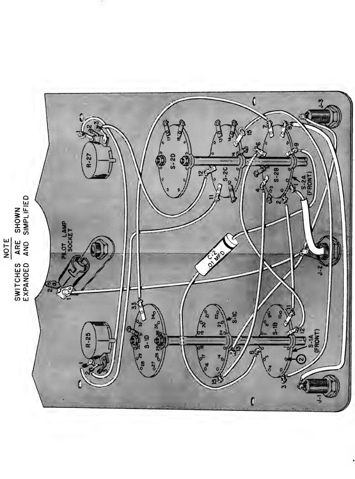
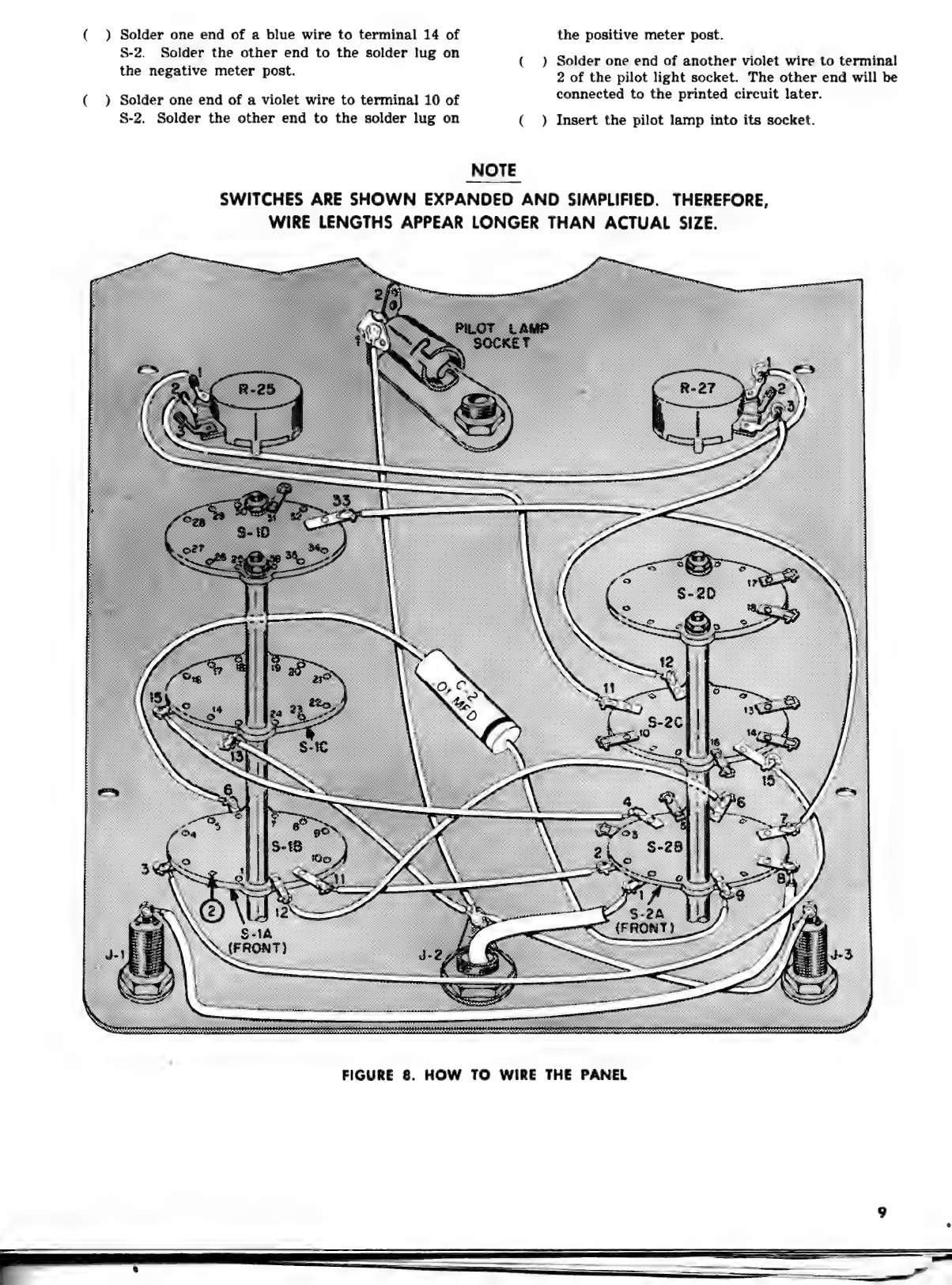
HOW
TO
WIRE
THE
PANEL
SEE
FIGURE
8.
(
)
Solder
one
end
of
a
green
wire
to
terminal
1
on
the
pilot
light
socket.
Connect,
but
do
not
sol-
der,
the
other
end
to
the
solder
lug
under
the
chassis
connector
nut.
Solder
one
end
of
an
orange
wire
to
terminal
13
on
§-1.
Connect,
but
do
not
solder,
the
other
end
to
the
solder
lug.
(
ie
Solder
one
end
of
another
orange
wire
to
the
terminal
on
J-3,
the
common
jack.
Solder
the
other
end
to
the
solder
lug.
(
)
Pass
one
end
of
a
red
wire
through
the
chassis
connector.
Solder
it
to
the
eyelet
in
the
center
of
the
connector.
Insert
the
other
end
through
a
11%
inch
length
of
the
large
spaghetti.
Force
the
spaghetti
down
against
the
soldered
eyelet
connection.
Solder
the
other
end
of
the
red
wire
to
terminal
1
of
S-2.
(_)
Insert
each
end
lead
of
C-2,
.01
MFD
paper
ca-
pacitor,
through
a
114
inch
length
of
small
spa-
ghetti.
Solder
the
lead
from
the
banded
end
to
terminal
9
of
S-2.
Solder
the
other
lead
to
termi-
nal
6
of
S-1.
Position
C-2
between
J-2
and
S-2A.
(
)
Solder
one
end
of
a
red
wire
to
terminal
11
of
S-1.
Solder
the
other
end
to
terminal
2
of
S-2.
( )
Solder
one
end
of
a
yellow
wire
to
terminal
12
of
8-1.
Solder
the
other
end
to
terminal
6
of
S-2.
( )
Insert
a
green
wire
through
a
414
inch
length
of
the
large
spaghetti.
Solder
one
end
to
J-1.
Sol-
der
the
other
end
to
terminal
8
of
S-2.
(
)
Solder
one
end
of
a
green
wire
to
terminal
3
of
S-1.
Connect,
but
do
not
solder,
the
other
end
to
terminal
15
of
S-2.
(
)
Solder
one
end
of
a
yellow
wire
to
terminal
1
of
R-25.
Solder
the
other
end
to
terminal
11
of
§-2.
(
)
Solder
one
end
of
a
blue
wire
to
terminal
2
of
R-25.
Connect,
but
do
not
solder,
the
other
end
to
terminal
1
of
R-27.
(_)
Solder
one
end
of
a
green
wire
to
terminal
33
of
S-1.
Solder
the
other
end
to
terminal
7
of
8-2.
(
)
Solder
one
end
of
a
red
wire
to
terminal
12
of
S-2.
Connect,
but
do
not
solder,
the
other
end
to
terminal
3
of
R-27.
(
)
Solder
one
end
of
a
green
wire
to
terminal
15
of
8-1.
Solder
the
other
end
to
terminal
4
of
S-2.
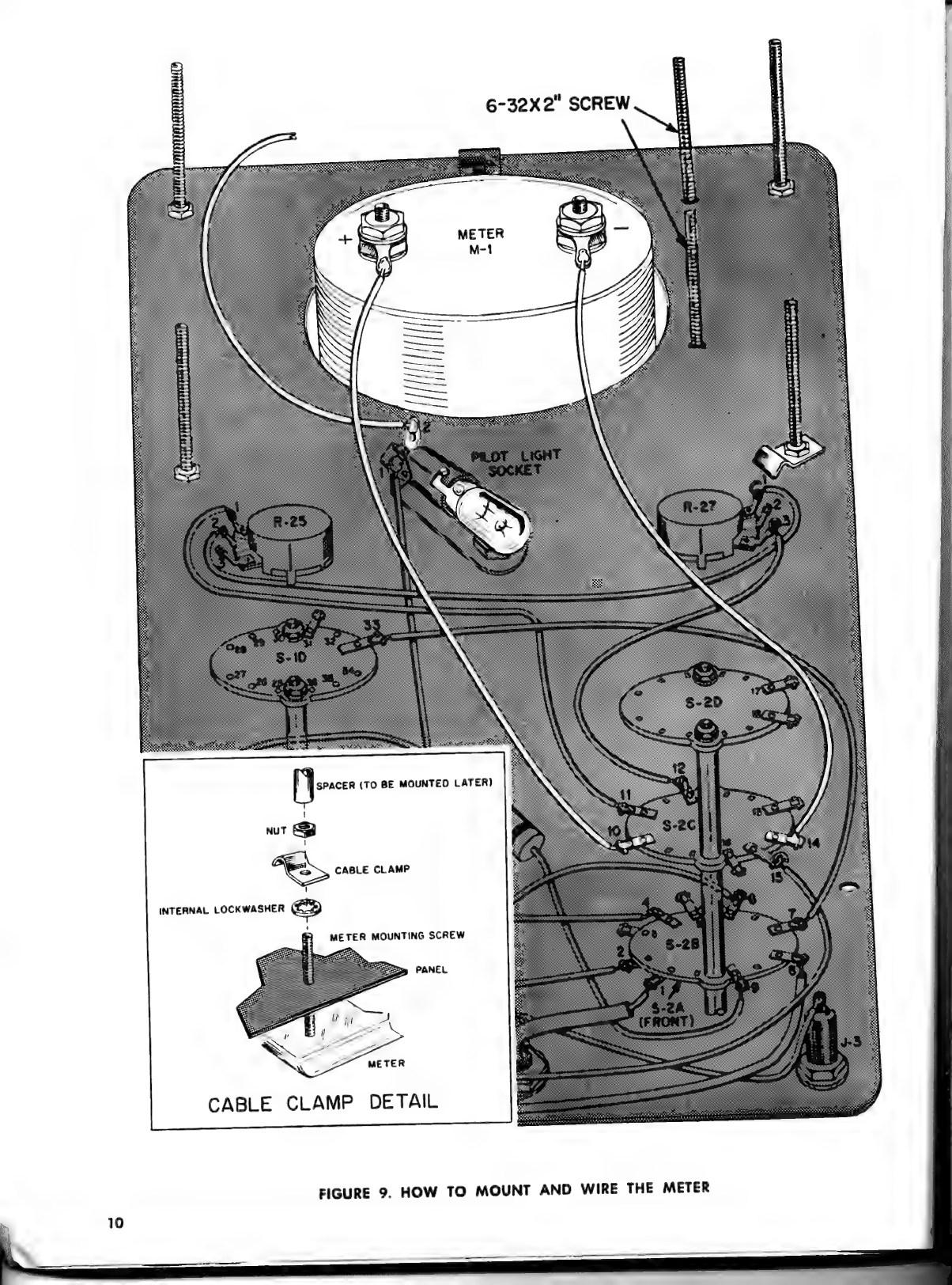
SEE
FIGURE
9.
(
)
Be
sure
the
paint
is
scraped
from
around
the
lower
right
meter
mounting
hole
on
the
rear
of
the
panel.
(
)
Insert
the
two
6-32
x
2”
screws
through
the
holes
in
the
panel
where
shown.
These
screws
are
held
in
place
by
the
meter
which
is
mounted
in
the
next
step.
(
)
Mount
the
meter
from
the
front
of
the
panel
over
the
heads
of
the
two
screws
set
in
the
panel.
Tighten
one
of
the
nuts
supplied
with
the
meter
over
each
of
the
two
top
screws
and
the
lower
left
screw.
Do
not
tighten
them
too
securely.
Place
an
internal
tooth
lockwasher
and
the
other
cable
clamp
over
the
lower
right
screw.
Now,
tighten
a
nut
over
the
screw.
The
other
four
nuts
supplied
with
the
meter
are
used
to
mount
the
printed
circuit
board.
NOTE:
If
the
meter
was
supplied
with
a
shorting
|
wire
between
the
meter
terminals,
remove
this
wire
(
)
Solder
one
end
of
a
blue
wire
to
terminal
14
of
the
positive
meter
post.
oa
solder
he
ean
fouthe
solder.
1Ue
On
(
)
Solder
one
end
of
another
violet
wire
to
terminal
the
negative
meter
post,
2
of
the
pilot
light
socket.
The
other
end
will
be
(
)
Solder
one
end
of
a
violet
wire
to
terminal
10
of
connected
to
the
printed
circuit
later.
S-2.
Solder
the
other
end
to
the
solder
lug
on
(
)
Insert
the
pilot
lamp
into
its
socket.
NOTE
SWITCHES
ARE
SHOWN
EXPANDED
AND
SIMPLIFIED.
THEREFORE,
WIRE
LENGTHS
APPEAR
LONGER
THAN
ACTUAL
SIZE.
<——o
FIGURE
8.
HOW
TO
WIRE
THE
PANEL
6-32X2"
SCREW
peerrerry
ete
rrcrreererorRED
meee
pepbpprrerstsy
AS
PFeees
MUU
a
a
ee
SOOT
Sean
pENCI
Reon
TEE
SRN
[sce
(TO
BE
MOUNTED
LATER)
nut
SQ
CABLE
CLAMP
INTERNAL
LOCKWASHER
ASSEMBLING
THE
PRINTED
CIRCUIT
BOARD
You
are
ready
to
mount
the
parts
on
the
printed
circuit
board.
Examine
it.
One
side
shows
the
out-
line
and
value
of
each
part
to
be
mounted.
That
is,
the
capacitors,
resistors,
the
transformer,
the
battery,
etc.,
are
pictured
in
their
exact
location.
The
following
procedure
assures
well
soldered
con-
nections
on
the
printed
circuit
board.
Study
it.
1.
INSERT
the
wire
leads
of
the
parts
through
the
holes
as
shown
in
Figure
11.
2.
BEND
LEADS
FLAT
against
the
foil
side
of
the
board
so
the
part
is
held
securely
in
place.
3.
SOLDER
EACH
LEAD
of
each
part
(after
all
parts
are
mounted)
right
at
the
hole
in
the
metal
foil
where
the
lead
comes
through.
Be
sure
you
heat
the
connection
until
the
solder
runs
and
spreads.
4.
CUT OFF
EACH
LEAD
as
close
as
possible
to
the
board.
Inspect
each
lead
after
cutting
it
off
to
be
sure
it
does
not
short
across
the
bakelite
from
one
foil
conductor
to
another.
This
would
cause
a
short
and
your
VTVM
won't work.
If
a
soldered
connection
should
have
a
dull
appear-
ance
it
is
not
a
good
solder
connection.
Using
more
solder,
again
solder
the
connection.
Do
not
use
so
much
solder
that
it
runs
off
the
printed
foil
wiring
onto
the
board
and
touches,
another
foil
conductor.
This
may
cause
an
intermittent
or
a
short
between
connection
points.
Before
you
solder
the
tabs
of
the
tube
sockets
to
the
metal
foil,
insert
the
tubes
in
the
sockets.
When
you
solder
the
tabs
of
the
tube
sockets
to
the
metal
foil,
heat
the
tube
socket
tab
until
the
solder
runs
down
onto
the
metal
foil
and
spreads.
After
you
have
soldered
all
the
connections
on
the
printed
circuit
board,
but
before
you
put
in
the
cable,
examine
the
metal
foil
side
of
the
board
carefully.
Again
be
sure
no
solder
or
cut-off
lead
touches
any
foil
conductor
except
the
one
to
which
it is
soldered.
Also,
be
sure
the
tabs
of
the
controls
have
not
been
bent
so
much
that
they
touch
any
other
conductor.
If
the
flux
from
the
solder
has
run
out
around
the
connections
that
is
all
right.
The
flux
is
not
conductive.
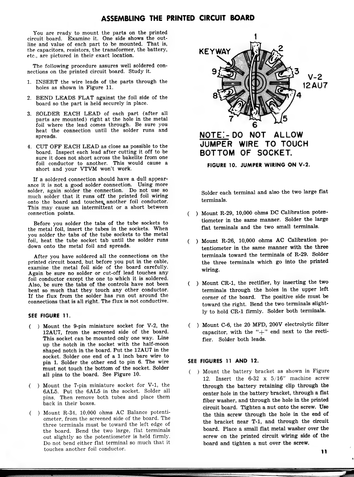
SEE
FIGURE
11.
(
)
Mount
the
9-pin
miniature
socket
for
V-2,
the
12AU7,
from
the
screened
side
of
the
board.
This
socket
can
be
mounted
only
one
way.
Line
up
the
notch
in
the
socket
with
the
half-moon
shaped
notch
in
the
board.
Put
the
12AU7
in
the
socket.
Solder
one
end
of
a
1
inch
bare
wire
to
pin
1.
Solder
the
other
end
to
pin
6.
The
wire
must
not
touch
the
bottom
of
the
socket.
Solder
all
pins
to
the
board.
See
Figure
10.
(
)
Mount
the
7-pin
miniature
socket
for
V-1,
the
6AL5.
Put
the
6AL5
in
the
socket.
Solder
all
pins.
Then
remove
both
tubes
and
place
them
back
in
their
boxes.
( )
Mount
R-34,
10,000
ohms
AC
Balance
potenti-
ometer,
from
the
screened
side
of
the
board.
The
three
terminals
must
be
toward
the
left
edge
of
the
board.
Bend
the
two
large,
flat
terminals
out
slightly
so
the
potentiometer
is
held
firmly.
Do
not
bend
either
flat
terminal
so
much
that
it
touches
another
foil
conductor.
NOTE.-DO
NOT
ALLOW
JUMPER
WIRE
TO
TOUCH
BOTTOM
OF
SOCKET.
FIGURE
10.
JUMPER
WIRING
ON
V-2.
Solder
each
terminal
and
also
the
two
large
flat
terminals.
(
)
Mount
R-29,
10,000
ohms
DC
Calibration
poten-
tiometer
in
the
same
manner.
Solder
the
large
flat
terminals
and
the
two
small
terminals.
(
)
Mount
R-26,
10,000
ohms
AC
Calibration
po-
tentiometer
in
the
same
manner
with
the
three
terminals
toward
the
terminals
of
R-29.
Solder
the
three
terminals
which
go
into
the
printed
wiring.
( )
Mount
CR-1,
the
rectifier,
by
inserting
the
two
terminals
through
the
holes
in
the
upper
left
corner
of
the
board.
The
positive
side
must
be
toward
the
right.
Bend
the
two
terminals
slight-
ly
to
hold
CR-1
firmly.
Solder
both
terminals.
(
)
Mount
C-6,
the
20
MFD,
200V
electrolytic
filter
capacitor,
with
the
“+”
end
next
to
the
recti-
fier.
Solder
both
leads.
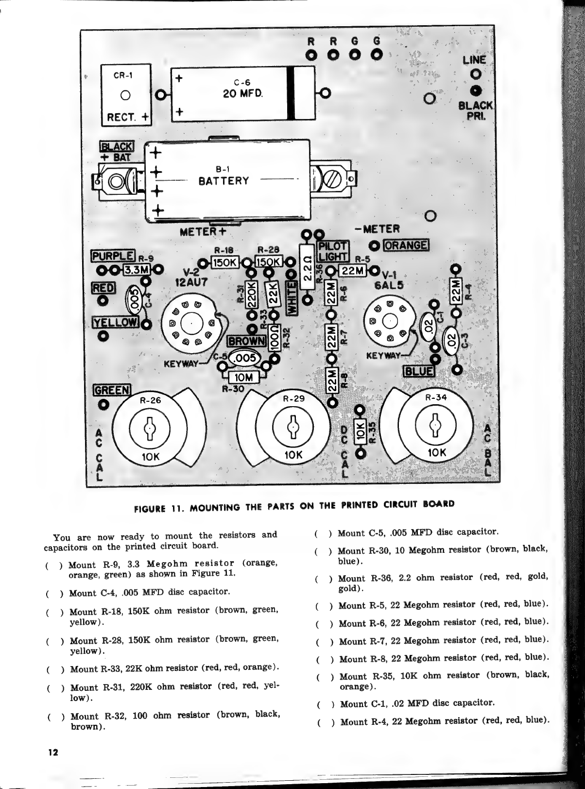
SEE
FIGURES
11
AND
12.
(
)
Mount
the
battery
bracket
as
shown
in
Figure
12.
Insert
the
6-32
x
5/16”
machine
screw
through
the
battery
retaining
clip
through
the
center
hole
in
the
battery
bracket,
through
a
flat
fiber
washer,
and
through
the
hole
in
the
printed
circuit
board.
Tighten
a
nut
onto
the
screw.
Use
the
thin
screw
through
the
hole
in
the
end
of
the
bracket
near
T-1,
and
through
the
circuit
board.
Place
a
small
flat
metal
washer
over
the
screw
on
the
printed
circuit
wiring
side
of
the
board
and
tighten
a
nut
over
the
screw.
WwW
B-1
BATTERY
FIGURE
11.
MOUNTING
THE
PARTS
ON
THE
PRINTED
CIRCUIT
BOARD
You
are
now
ready
to
mount
the
resistors
and
capacitors
on
the
printed
circuit
board.
(
)
Mount
R-9,
3.3
Megohm
resistor
(orange,
orange,
green)
as
shown
in
Figure
11.
Mount
C-4,
.005
MFD
disc
capacitor.
Mount
R-18,
150K
ohm
resistor
(brown,
green,
yellow).
Mount
R-28,
150K
ohm
resistor
(brown,
green,
yellow).
Mount
R-33,
22K
ohm
resistor
(red,
red,
orange).
Mount
R-31,
220K
ohm
resistor
(red,
red,
yel-
low).
Mount
R-32,
100
ohm
resistor
(brown,
black,
brown).
(
(
PONS
)
)
al
)
)
Mount
C-5,
.005
MFD
disc
capacitor.
Mount
R-30,
10
Megohm
resistor
(brown,
black,
blue).
Mount
R-36,
2.2
ohm
resistor
(red,
red,
gold,
gold).
Mount
R-5,
22
Megohm
resistor
(red,
red,
blue).
Mount
R-6,
22
Megohm
resistor
(red,
red,
blue).
Mount
R-7,
22
Megohm
resistor
(red,
red,
blue).
Mount
R-8,
22
Megohm
resistor
(red,
red,
blue).
Mount
R-35,
10K
ohm
resistor
(brown,
black,
orange).
Mount
C-1,
.02
MFD
disc
capacitor.
Mount
R-4,
22
Megohm
resistor
(red,
red,
blue).

MOUNTING
BRACKET:
FIBER
WASHER
(3)
‘el
AYNSIS
J317€aV9
3HL
ONILOANNOD
ce
Oe
oe
a
rae
WALA
LH9SIN»

AN
igi
alata
ican
maa
aaa
( )
Mount
C-3,
.02
MFD
disc
capacitor.
Note
that
the
leads
of
this
capacitor
must
be
positioned
so
that
they
clear
the
hole
for
mounting
the
printed
circuit
to
the
panel.
Turn
the
circuit
board
over
and
solder
each
con-
nection.
Remember
to
use
a
small
iron
and
the
rosin-core
solder
supplied.
Be
sure
the
connec-
tion
where
R-18,
R-28,
and
R-31
join
is
well
soldered.
Cut
off
each
end
lead
close
to
the
soldered
connection.
FINAL
WIRING
You
are
now
ready
to
prepare
the
cable
and
do
the
final
wiring
on
your
VTVM.
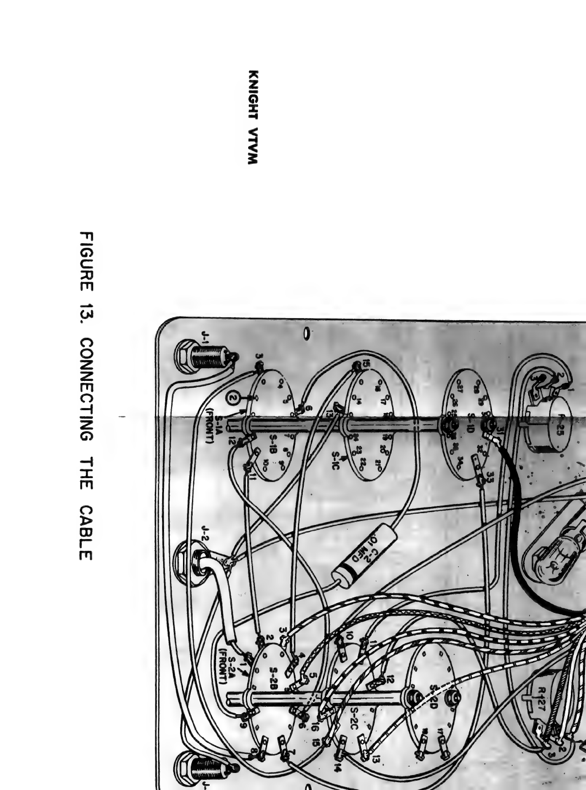
SEE
FIGURE
13.
(
NNN
)
~
—
~—
eee
Carefully
remove
414
inches
of
the
outer
insula-
tion
from
one
end
of
the
cable.
Be
very
careful
not
to
cut
the
insulation
of
any
of
the
wires.
Now,
trim
the
wires
to
the
following
lengths:
Orange:
Leave
it
the
full
414
inches.
Green:
1”
Yellow:
1”
Red:
1144”
Violet:
13,”
Black:
2354”
Brown:
24,”
White:
314”
Blue:
414”
Remove
14
inch
of
insulation
from
the
end
of
each
wire.
Coat
each
end
with
solder.
Solder
the
black
wire
to
the
terminal
on
the
bat-
tery
bracket
marked
+
Bat.
This
wire
does
not
go
through
the
printed
circuit
board.
Insert
each
of
the
other
wires
into
the
hole
in
the
board
marked
with
the
corresponding
color.
Solder
each
on
the
printed
wiring
side
of
the
board.
Remove
334”
of
the
outer
insulation
from
the
other
end
of
the
cable.
Trim
each
wire
as
fol-
lows:
Red:
Leave
it
the
full
334”
White:
234”
Brown:
214”
Violet:
114”
Yellow:
234,”
Blue:
3”
Green:
334”
Orange:
2”
Black:
3”
Remove
1,”
of
insulation
from
the
end
of
each
wire.
Coat
each
end
with
solder.
Solder
the
violet
wire
to
terminal
5
of
S-2.
Solder
the
brown
wire
to
terminal
3
of
R-27.
Solder
the
white
wire
to
terminal
2
of
R-27.
Solder
the
red
wire
to
terminal
1
of
R-27.
Solder
the
yellow
wire
to
terminal
13
of
S-2.
BATTERY
RETAINING
CLIP
SMALL
en
ie
oe
a
wee
*—
PRINTED
CIRCUIT
BOARD
SMALL
|
I
i
2)
———-NUT
|
i
i
Solder
the
blue
wire
to
terminal
15
of
S-2.
Solder
the
green
wire
to
terminal
16
of
S-2.
Solder
the
orange
wire
to
terminal
3
of
S-2.
Solder
the
black
wire
to
terminal
31
of
S-1.
Solder
the
violet
wire
from
terminal
2
of
the
pilot
light
socket
to
PILOT
LIGHT
on
the
print-
ed
circuit
board.
Bring
this
wire
over
the
screen-
ed
side
of
the
board.
Put
one
of
the
spacers
over
each
of
the
six
mounting
screws.
Place
three
of
the
large
fiber
washers
over
the
screw
shown.
Place
the
mounting
bracket
over
this
screw
and
the
top
right
meter
mounting
screw.
Place
four
of
the
large
fiber
washers
over
the
screw
shown.
SEE
FIGURE
14
(
)
The
printed
circuit
board
will
be
mounted
on
six
mounting
screws.
First
place
a
large
fiber
wash-
er
on
the
single
screw
in
the
corner
of
the
panel
(upper
left
corner
in
Figure
14).
Then
mount
the
board
on
the
six
screws.
Place
another
large
fiber
washer
on
top
of
the
board,
over
the
same
corner
screw.
Secure
the
board
with
a
split
wash-
er
and
nut
on
each
of
the
four
screws,
as
shown
in
Figure
14.
Trim
the
leads
of
T-1,
the
power
transformer
to
the
following
lengths:
The
black
lead
toward
the
top
right
corner
to
114”,
The
other
black
lead
to
6”.
Both
green
leads
to
114”.
Both
red
leads
to
2”.
13

FIGURE
13.
HOW
TO
CONNECT
THE
CABLE
(
14
FROM
TERMINAL
2
ON
PILOT
LIGHT
SOCKET
SWITCHES
AND
CABLE
ARE
SHOWN
EXPANDED
AND
SIMPLIFIED.
THERE-
FORE,
WIRE
LENGTHS
APPEAR
LONGER
THAN
ACTUAL
SIZE.
~
PURPLE}
go
NOTE
Remove
the
insulation
from
¥,”
of
the
end
of
each
lead.
Hold
the
lead
with
pliers
close
to
the
transformer
as
you
remove
the
insulation.
Coat
the
stripped
end
of
each
lead
with
solder.
Mount
T-1
on the
remaining
two
mounting
screws,
with
the
leads
positioned
as
shown.
Place
three
large
fiber
washers
under
the
mounting
tab
shown
and
fasten
the
transformer
with
two
split
washers
and
nuts.
)
Connect
the
leads
of
T-1
as
follows:
Solder
the
short
black
lead
in
the
hole
marked
MOUNTING
BRACKET,
BLACK
PRI.
Solder
the
long
black
lead
to
terminal
18
of
S-2.
Solder
the
green
leads
into
the
holes
marked
G.
:
Solder
the
red
leads
into
the
holes
marked
R.
|
(
)
Slide
the
bare
ends
of
the
line
cord
under
the
:
cable
clamp.
Tie
a
knot
in
the
cord
5”
from
the
|
bare
ends.
Split
the
cord
back
to
the
knot.
Solder
one
wire
in
the
hole
marked
LINE
on
the.
board.
Cut
214”
of
the
other
wire.
Solder
it
to
terminal
17
of
S-2.
|
|
Table of contents
Other Allied Radio Test Equipment manuals


