Allied Radio Knight KG-640 User manual

!
OPERATOR’S
MANUAL
A
\
KG-640
20,000
|
OHMS/VOLT
|
5s
VOM
;
TABLE
OF
CONTENTS
SPECIFICATIONS
..............
0.
cece
eee
eee
ee
eee
3
DESCRIPTION
OF
CONTROLS
...................2..
4
OPERATING
NOTES
.............
0... cece
eee
eee
5
MEASURING
DC
VOLTS
...................-
2008
6-9
MEASURING
AC
VOLTS
...................-..005-
10-11
SCHEMATIC
orice
sce
aie
eee
Honk
Hew Sew
we
Ae
eS
12-13
MEASURING
RESISTANCE
........................
14-15
MEASURING
DC
CURRENT
...................-4-.
16-17
MEASURING
AC
CURRENT
.......................
18
MEASURING
OUTPUT
VOLTS
......................
19
MEASURING
DB
(Decibels)
....................0.
20-21
MAINTENANCE
...........
0.20.0...
.
cee
eee
eee
22
PARTS
UIST:
0...
cites
coe
eb
ee
eda
oede
ees
23
WARRANTY
oi
eci
eee
eea
ere
as
eae
ba
See
ee
bbe
24
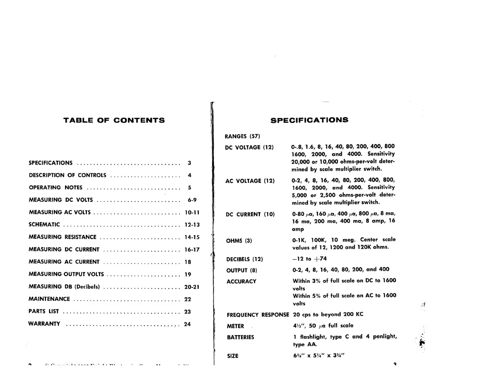
SPECIFICATIONS
RANGES
(57)
DC
VOLTAGE
(12)
AC
VOLTAGE
(12)
DC
CURRENT
(10)
OHMS
(3)
DECIBELS
(12)
OUTPUT
(8)
ACCURACY
FREQUENCY
RESPONSE
METER
BATTERIES
SIZE
0-.8,
1.6,
8,
16,
40,
80,
200,
400,
800
1600,
2000,
and
4000.
Sensitivity
20,000
or
10,000
ohms-per-volt
deter-
mined
by
scale
multiplier
switch.
0-2,
4,
8,
16,
40,
80,
200,
400,
800,
1600,
2000,
and
4000.
Sensitivity
5,000
or
2,500
ohms-per-volt
deter-
mined
by
scale
multiplier
switch.
0-80
2a,
160
a,
400
pa,
800
pa,
8
ma,
16
ma,
200
ma,
400
ma,
8
amp,
16
amp
0-1K,
100K,
10
meg.
Center
scale
values
of
12,
1200
and
120K
ohms.
—12
to
+74
0-2,
4,
8,
16,
40,
80,
200,
and
400
Within
3%
of
full
scale
on
DC
to
1600
volts
Within
5%
of
full
scale
on
AC
to
1600
volts
20
cps
to
beyond
200
KC
42",
50
na
full
scale
1
flashlight,
type
C
and
4
penlight,
type
AA.
6%"
x
5%"
x
334"

The
Knight
VOM
has
been
designed
with
the
service
technician
in
mind.
It
has
57
ranges
and
incorporates
a
414”,
50
p»amp,
mirror
scale
meter
movement
that
eliminates
parallax
errors.
Factory
selected
calibrating
resistors
compensate
for
the
indi-
vidual
characteristics
of
the
meter
movement
and
AC
rectifiers.
High
quality
1%
multiplier
resistors
assure
3%
accuracy
on
DC
and
5%
on
AC.
DESCRIPTION
OF
CONTROLS
SELECTOR
SWITCH
Selects
the
function,
—AC
volts,
DC
volts
etec.......
;
and
the
individual
ranges
within
the
function.
POLARITY
REVERSE
SWITCH
Allows
the
reversal
of
polarity
to
the
meter
without
having
to
change
the
connection
of
the
test
leads
to
the
circuit
under
AC
test.
It
should
be
set
in
the
+DC
when
measuring
AC
voltages.
SCALE
MULTIPLIER
SWITCH
Provides
a
range-dividing
function,
effectively
doubling
the
number
of
usable
ranges
for
voltage
and
current
measure-
VA
ments.
This
switch
must
be
set
in
the
0
<a
position
when
making
resistance
measurements.
OPERATING
NOTES
Before
any
measurements
are
made,
be
sure
the
instrument
is
placed
flat
on
a
bench
where
the
measurements
will
be
per-
formed.
Always
check
that
the
meter
pointer
is
lined
up
with
the
zeros
on
the
left
hand
side.
If
the
pointer
does
not
fall
in
line
with
these
marks,
turn
the
nylon
screw
directly
above
the
word
“OFF”
either
left
or
right
until
the
pointer
is
positioned
correctly.
Although
this
meter
is
very
similar
to
many
meters
on
the
market
today,
it
is
recommended
that
you
read
all
of
the
mate-
rial
on
the
following
pages.
It
will
be
important
to
you
to
fully
understand
the
capabilities
of
the
meter
before
you
begin
using
it.
When
the
meter
is
used
to
measure
DC
voltages,
polarity
should
be
observed.
The
black
test
lead
is
plugged
in
the
-COM
jack
and
should
be
connected
to
the
low
or
common
side
of
the
circuit
in
which
the
voltage
is
to
be
measured.
The
red
test
lead
is
plugged
into
the
VOA
jack
and
should
be
connected
to
the
high
side
of
the
circuit.
In
some
cases
where
the
polarity
is
not
known,
touch
the
red
test
lead
to
the
circuit
to
get
an
indication
of.
meter
deflection.
Once
an
indication
has
been
obtained,
the
polarity
switch
can
be
set
correctly.
When
using
the
meter
be
sure
to
take
into
consideration
the
loading
effects
the
meter
will
have
on
any
high
impedance
cir-
cuit.
This
is
especially
true
on
the
low
AC
and
DC
ranges.

HOW
TO
MEASURE
DC
VOLTAGES
Place
the
meter
in
front
of
you
where
the
face
can
be
viewed
directly.
[1]
Plug
the
black
test
lead
into
the
jack
marked
-COM
and
the
red
test
lead
into
the
VOA
jack.
[]
Set
the
upper
slide
switch
to
+DC
for
positive
voltage
read-
ings.
For
negative
voltage
readings,
set
the
slide
switch
to
—DC.
[J
Rotate
the
selector
switch
to
the
DCV
range
which
will
pro-
vide
a
reading
at
the
right
hand
side
of
the
scale.
NOTE:
It
is
always
a
good
practice
to
start
with
the
highest
range
available.
Then,
after
first
indication,
the
switch
should
be
reset
to
the
position
in
which
more
accurate
readings
can
be
obtained.
If
possible,
make
final
readings
on
a
range
which
provides
readings
in
the
right
hand
half
of
the
scale,
since
meter
accuracy
is
based
on
full
scale
value.
[7
Touch
the
black
test
lead
to
the
negative
side
of
the
circuit
in
which
the
DC
voltage
reading
is
to
be
made.
[|
Then
leaving
one
hand
free,
touch
the
red
test
lead
to
the
positive
point
in
the
circuit.
The
value
of
the
measured
voltage
can
now
be
read
from
the
appropriate
meter
scale,
taking
into
account
the
range
setting
of
the
selector
switch
and
the
setting
of
the
scale
multiplier
switch.
CAUTION:
When
measuring
high,
lethal
voltages,
it is
best
to
disconnect
power
from
the
equipment
under
test
before
con-
necting
the
meter.
In
cases
where
it is
impossible
to
do
this,
connect
the
leads
separately
and
use
only
one
hand
at
any
one
time.
Grasp
the
test
prod
well
back
from
the
metal
tip
and
make
momentary
contact
with
the
circuit
under
test
by
letting
the
metal
tip
of
the
prod
touch
the
point
at
which
the
potential
exists.
Never
touch
part
of
the
equipment
under
test
with
the
other
hand.
O
VALA
-COM

HOW
TO
MEASURE
DC
VOLTAGES
(Continued)
For
all
DC
voltage
readings,
use
only
the
black
scales
marked
DC.
For
readings
of
0
-.8
volts,
set
the
selector
switch
to
1.6
and
the
scale
multiplier
switch
to
™“.
Read
on
the
0-80
DC
scale,
each
division
being
equal
to
.02
of
a
volt.
For
readings
of
0-1.6
volts,
set
the
selector
switch
to
1.6
and
the
scale
multiplier
switch
to
VA.
Read
on
the
0-16
DC
scale,
each
division
being
equal
to
.04
of
a
volt.
For
readings
of
0-8
volts,
set
the
selector
switch
to
16
and
the
scale
multiplier
switch
to
we
Read
on
the
0-80
DC
scale,
each
2
division
being
equal
to
.2
of
a
volt.
For
readings
of
0-16
volts,
set
the
selector
switch
to
16
and
the
scale
multiplier
switch
to
VA.
Read
on
the
0-16
DC
scale,
—
each
division
being
equal
to
.4
of
a
volt.
For
readings
of
0-40
volts,
set
the
selector
switch
to
80
and
the
scale
multiplier
switch
to
he
Read
on
the
0-400
DC
scale,
—
each
division
being
equal
to
1
volt.
For
readings
of
0-80
volts,
set
the
selector
switch
to
80
and
the
scale
multiplier
switch
to
VA.
Read
on
the
0-80
DC
scale,
—
each
division
being
equal
to
2
volts.
For
readings
of
0-200
volts,
set
the
selector
switch
to
400
and
the
scale
multiplier
switch
to
Read
on
the
0-200
DC
scale,
—
each
division
being
equal
to
5
volts.
For
readings
of
0-400
volts,
set
the
selector
switch
to
400
and
the
scale
multiplier
to
VA.
Read
on
the
0-400
DC
scale,
—
each
division
being
equal
to
10
volts.
4000
For
readings
of
0-800
volts,
set
the
selector
switch
to
1600
and
the
seale
multiplier
switch
to
“.
Read
on
0-80
DC
scale,—each
division
being
equal
to
20
volts.
4000
For
readings
of
0-1600
volts,
set
the
selector
switch
to
1600
and
the
scale
multiplier
switch
to
VA.
Read
on
the
0-16
DC
scale,
—
each
division
being
equal
to
40
volts.
4000
For
readings
of
0-2000
volts,
set
the
selector
switch
to
1600
and
the
scale
multiplier
switch
to
ie
Place
the
red
test
lead
into
the
+4KV
jack
marked
DC.
Read
on
the
0-200
DC
scale,
—
each
division
being
equal
to
50
volts.
4000
For
readings
of
0-4000
volts,
set
the
selector
switch
to
1600
and
the
scale
multiplier
switch
to
VA.
Place
the
red
test
lead
into
+4KV
the
jack
marked
DC.
Read
on
the
0-400
DC
scale,
—
each
divi-
sion
being
equal
to
100
volts.
NOTE:
If
working
with
high
potentials
of
this
order,
make
doubly
sure
that
the
CAUTION
paragraph
at
the
beginning
of
this
section
is
strictly
observed.

HOW
TO
MEASURE
AC
VOLTAGES
[-]
Plug
the
black
test
lead
into
the
jack
marked
-COM.
Plug
the
red
test
lead
into
the
jack
marked
VOA.
(]
Set the
upper
slide
switch
to
AC.
(]
Rotate
the
selector
switch
to
the
ACV
range
which
will
pro-
vide
a
reading
at
the
right
hand
side
of
the
scale.
[|
Clip
the
black
test
lead
to
one
terminal
of
the
voltage
to
be
measured
and
the
red
test
lead
to
the
other.
NOTE:
For
high
voltages,
follow
the
same
precautions
as
noted
in
the
section
on
‘HOW
TO
MEASURE
DC
VOLTAGES”.
Use
the
RED
AC
scales
for
voltage
readings
of
2,
4
and
8
volts.
The
BLACK
scales
are
used
for
voltage
readings
of
16
through
4000
volts.
For
readings
of
0-2
volts,
set
the
selector
switch
to
4
and
the
scale
multiplier
switch
to
aie
Read
on
the
RED
0-2
AC
scale,
—
each
division
being
equal
to
.1
volt.
For
readings
of
0-4
volts,
set
the
selector
switch
to
4
and
the
scale
multiplier
switch
to
VA.
Read
on
the
RED
0-4
AC
scale,
each
division
being
equal
to
.2
of
a
volt.
For
readings
of
0-8
volts,
set
the
selector
switch
to
16
and
the
seale
multiplier
switch
to
ee
Read
on
the
RED
0-8
AC
scale.,
—each
division
being
equal
to
.2
of
a
volt.
For
readings
of
0-16
volts,
set
the
selector
switch
to
16
and
the
scale
multiplier
switch
to
VA.
Read
on
the
BLACK
0-16
AC
scale,
—
each
division
being
equal
to
.4
of
a
volt.
For
readings
of
0-40
volts,
set
the
selector
switch
to
80
and
the
scale
multiplier
switch
to
™.
Read
on
the
BLACK
0-400
AC
scale,
—-
each
division
being
equal
to
1
volt.
For
readings
of
0-80
volts,
set
the
selector
switch
to
80
and
the
scale
multiplier
switch
to
VA.
Read
on
the
BLACK
0-80
AC
scale,
—
each
division
being
equal
to
2
volts.
For
readings
of
0-200
volts,
set
the
selector
switch
to
400
and
the
scale
multiplier
switch
to
“.
Read
on
the
BLACK
0-200
AC
scale,
—
each
division
being
equal
to
5
volts.
For
readings
of
0-400
volts,
set
the
selector
switch
to
400
and
the
scale
multiplier
switch
to
=.
Read
on
the
BLACK
0-400
AC
scale,
—
each
division
being
equal
to
10
volts.
4000
For
readings
of
0-800
volts,
set
the
selector
switch
to
1600
and
the
scale
multiplier
switch
to
as
Read
on
the
BLACK
0-80
AC
scale,
—
each
division
being
equal
to
20
volts.
4000
For
readings
of
0-1600
volts,
set
the
selector
switch
to
1600
and
the
scale
multiplier
switch
to
VA.
Read
on
the
BLACK
0-16
AC
scale,
—
each
division
being
equal
to
40
volts.
4000
For
readings
of
0-2000
volts,
set
the
selector
switch
to
1600
and
the
scale
multiplier
switch
to
<=.
Place
the
red
test
lead
into
the
4KV
jack
marked
AC.
Read
on
the
BLACK
0-200
AC
scale,
—
each
division
being
equal
to
50
volts.
4000
For
readings
of
0-4000
volts,
set
the
selector
switch
to
1600
and
the
scale
multiplier
switch
to
VA.
Place
the
red
test
lead
into
4KV
the
jack
marked
AC.
Read
on
the
BLACK
0-400
AC
scale,
—
each
division
being
equal
to
100
volts.

ALL
RESISTORS
ARE
INDICATED
IN
OHMS.
Ke
S-IC
-1D
,000
OHMS.
S-1B
=
MEG
=
1,000,000
OHMS.
ALL
RESISTORS
ARE
1/2
WATT
i%
UNLESS
s-}A—
OTHERWISE
SPECIFIED.
*
SHUNT
WIRE
v
METER
Rm
@ALIBRATION
RESISTOR
|
RECTIFIER
Rb
CALIBRATION
RESISTORS
Loe
ee
=
VA
OC
VOLTS
AC
VOLTS
2
(vw/2)
v
Vv
{V/2)
(2000)
4000
=a
4000
(2000)
R-6
(800)
1600
1600
(800)
JPRriiy
Weis:
ete
Boe
12MEG
3MEG
{Ww
(200)
400
x
400
(200)
Iw
Se
R-7
R-12
3.2MEG
800K
7o
7!
oJ
(40)
re
53
|e,
80°
69
13
65
R-13
66
w
Af
56
16
160K
‘-
:
67
Peete
33
oT
Rig
ss
*.
a
19
ta
ptte:
3
*
.
read
Pay
SEMA
{.O8MA)
‘
IEMA
“2
ema
(.4MA)
7
sa
iN
F
.
1150
\ \
IGMA
(8MA)
\
aR
€
\
d
j
ie
400MA__(200MA)
R-I
§
(
16A
(BA)
-
|
18k
B-2
8-3
B-4\B-5
{t+
gh
R-21
1.22
—_—__)
R-20
$R-22
$R-23
SR-I9
c-I
R-18
R-I7
0312
31.6
a
6.33K
alyfd
6MEG
ISMEG
\}--
ww
WS
pi
2w
2W
ro
ve
ta
1-3
A-4

HOW
TO
MEASURE
RESISTANCE
CAUTION:
Before
making
any
resistance
measurements
in
a
circuit,
make
sure
that
the
power
is
turned
off.
It
is
also
good
practice
to
discharge
any
capacitors
in
the
part
of
the
circuit
in
which
resistance
measurements
are
to
be
made.
[]
Plug
the
black
test
lead into
the
jack
marked
-COM.
Plug
the
red
test
lead
into
the
jack
marked
VOA.
AC
[]
Place
the
polarity
reverse
switch
in
the
+DC
position.
Place
the
scale
multiplier
switch
in
the
ao“
position.
NOTE:
It
will
not
be
possible
to
zero
the
meter
on
any
range
if
the
scale
multiplier
switch
is
set
in
the
VA
position.
[]
Set the
selector
switch
to
the
XI
OHMS
range.
Connect
the
two
test
lead
ends
together.
Turn
the
OHMS
ADJ
control
until
the
meter
reads
0
on
the
RED
scale
marked
a.
The
XI
ohms
scale
is
now
calibrated
to
read
ohm
values
from
0-1000
ohms.
Use
this
same
procedure
to
calibrate
the
X100
and
X10K
ranges
before
any
measurements
are
made
on
these
ranges.
Connect
the
test
leads
to
the
terminals
of
the
unknown
resis-
tance
to
be
measured.
Observe
the
meter
reading.
Since
great-
est
accuracy
is
at
the
right
hand
side
of
the
scale,
switch
the
selector
switch
to
the
range
that
provides
maximum
deflection.
The
meter
should
be
re-calibrated
frequently
for
accurate
readings.
With
the
selector
switch
set
in
the
X1
position,
the
0-1K
ohm
range
is
covered;
center
scale
reading
is
12
ohms.
Read
the
scale
directly.
With
the
selector
switch
set
in
the
X100
position,
the 100
to
100K
ohm
range
is
covered;
center
scale
reading
is
1200
ohms.
Multiply
readings
by
100.
With
the
selector
switch
set
in
the
X10K
position,
the
10K
to
10
meg
ohm
range
is
covered;
center
scale
reading
is
120K.
Multiply
readings
by
10,000.
When
measuring
resistance,
a
current
is
made
to
flow
through
the
unknown
resistance.
Usually
this
current
is
so
small
that
it
can
be
neglected.
However,
on
the
X1
ohms
range,
currents
as
high
as
180
milliamps
will
flow
through
resistances
lower
than
6
ohms.
Therefore
it
is
good
practice
to
consider
the
cur-
rent
flow
first
when
measuring
the
D-C
resistance
of
a
device
which
can
safely
pass
only
low
currents
without
being
burned
out.
For
all
other
cases,
no
damage
will
result
as
long
as
the
ohmmeter
current
does
not
exceed
the
current
rating
of
the
unknown
resistance.
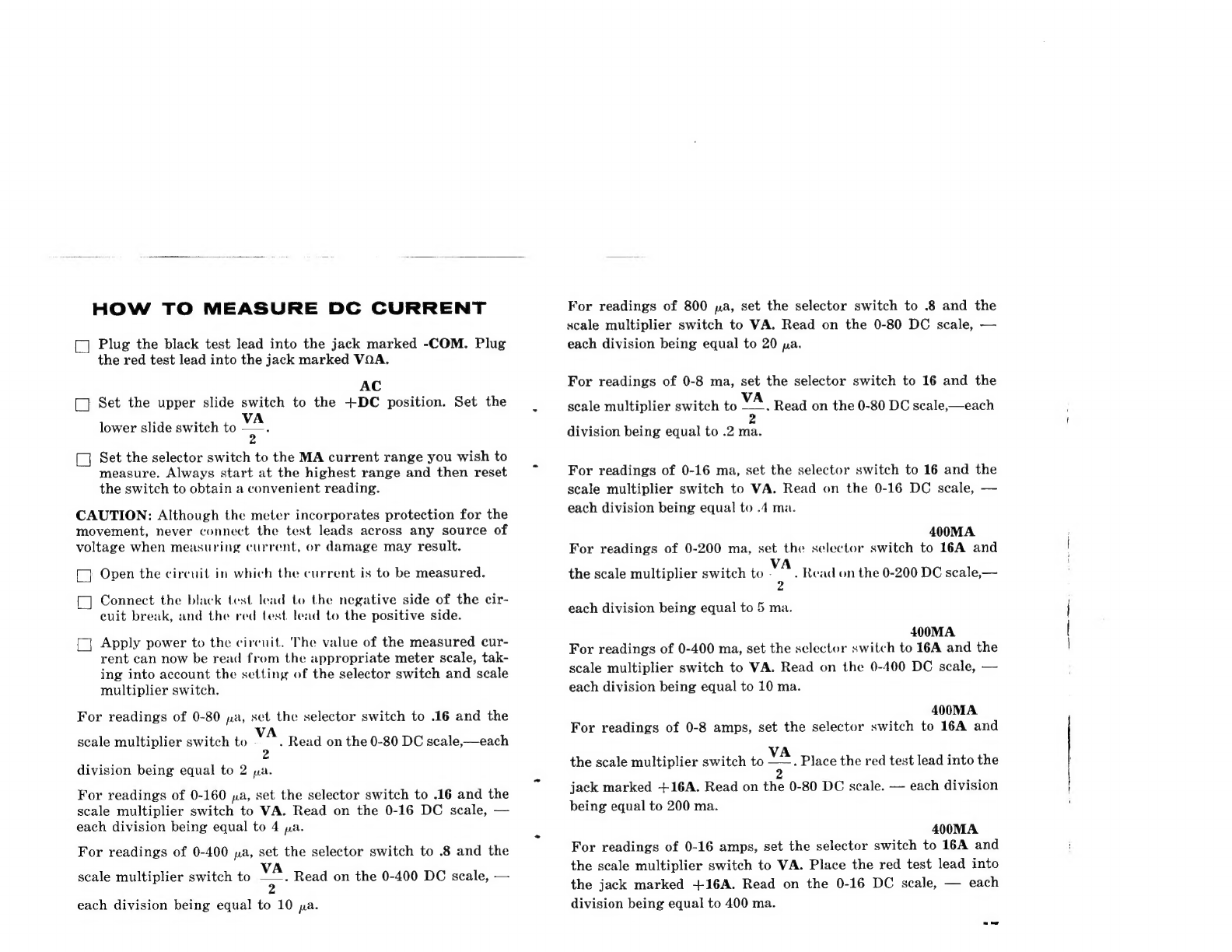
HOW
TO
MEASURE
DC
CURRENT
[]
Plug
the
black
test
lead into
the
jack
marked
-COM.
Plug
the
red
test
lead
into
the
jack
marked
VOA.
AC
_}
Set
the
upper
slide
switch
to
the
+DC
position.
Set
the
lower
slide
switch
to
Mes
(]
Set
the
selector
switch
to
the
MA
current
range
you
wish
to
measure.
Always
start
at
the
highest
range
and
then
reset
the
switch
to
obtain
a
convenient
reading.
CAUTION:
Although
the
meter
incorporates
protection
for
the
movement,
never
connect
the
test
leads
across
any
source
of
voltage
when
measuring
current,
or
damage
may
result.
-]
Open
the
circuit
in
which
the
current
is
to
be
measured.
Connect
the
black
test
lead
to
the
negative
side
of
the
cir-
cuit
break,
and
the
red
test.
lead
to
the
positive
side.
Apply
power
to
the
circuit.
The
value
of
the
measured
cur-
rent
can
now
be
read
from
the
appropriate
meter
scale,
tak-
ing
into
account
the
setting
of
the
selector
switch
and
scale
multiplier
switch.
For
readings
of
0-80
pa,
set
the
selector
switch
to
.16
and
the
scale
multiplier
switch
to
ae
Read
on
the
0-80
DC
scale,—each
division
being
equal
to
2
pa.
For
readings
of
0-160
ya,
set
the
selector
switch
to
.16
and
the
scale
multiplier
switch
to
VA.
Read
on
the
0-16
DC
scale,
—
each
division
being
equal
to
4
pa.
For
readings
of
0-400
ya,
set
the
selector
switch
to
.8
and
the
scale
multiplier
switch
to
“.
Read
on
the
0-400
DC
scale,
—
each
division
being
equal
to
10
pa.
For
readings
of
800
pa,
set
the
selector
switch
to
.8
and
the
scale
multiplier
switch
to
VA.
Read
on
the
0-80
DC
scale,
—
each
division
being
equal
to
20
pa.
For
readings
of
0-8
ma,
set
the
selector
switch
to
16
and
the
scale
multiplier
switch
to
Lice
Read
on
the
0-80
DC
scale,—each
2
division
being
equal
to
.2
ma.
For
readings
of
0-16
ma,
set
the
selector
switch
to
16
and
the
scale
multiplier
switch
to
VA.
Read
on
the
0-16
DC
scale,
—
each
division
being
equal
to
.4
ma.
400MA
For
readings
of
0-200
ma,
set
the
selector
switch
to
16A
and
the
scale
multiplier
switch
to
A
.
Read
on
the
0-200
DC
scale,—
zZ
each
division
being
equal
to
5
ma.
400MA
For
readings
of
0-400
ma,
set
the
selector
switch
to
16A
and
the
scale
multiplier
switch
to
VA.
Read
on
the
0-400
DC
scale,
—
each
division
being
equal
to
10
ma.
400MA
For
readings
of
0-8
amps,
set
the
selector
switch
to
16A
and
the
scale
multiplier
switch
to
va.
Place
the
red
test
lead
into
the
2
jack
marked
+16A.
Read
on
the
0-80
DC
scale.
—
each
division
being
equal
to
200
ma.
400MA
For
readings
of
0-16
amps,
set
the
selector
switch
to
16A
and
the
scale
multiplier
switch
to
VA.
Place
the
red
test
lead
into
the
jack
marked
+16A.
Read
on
the
0-16
DC
scale,
—
each
division
being
equal
to
400
ma.
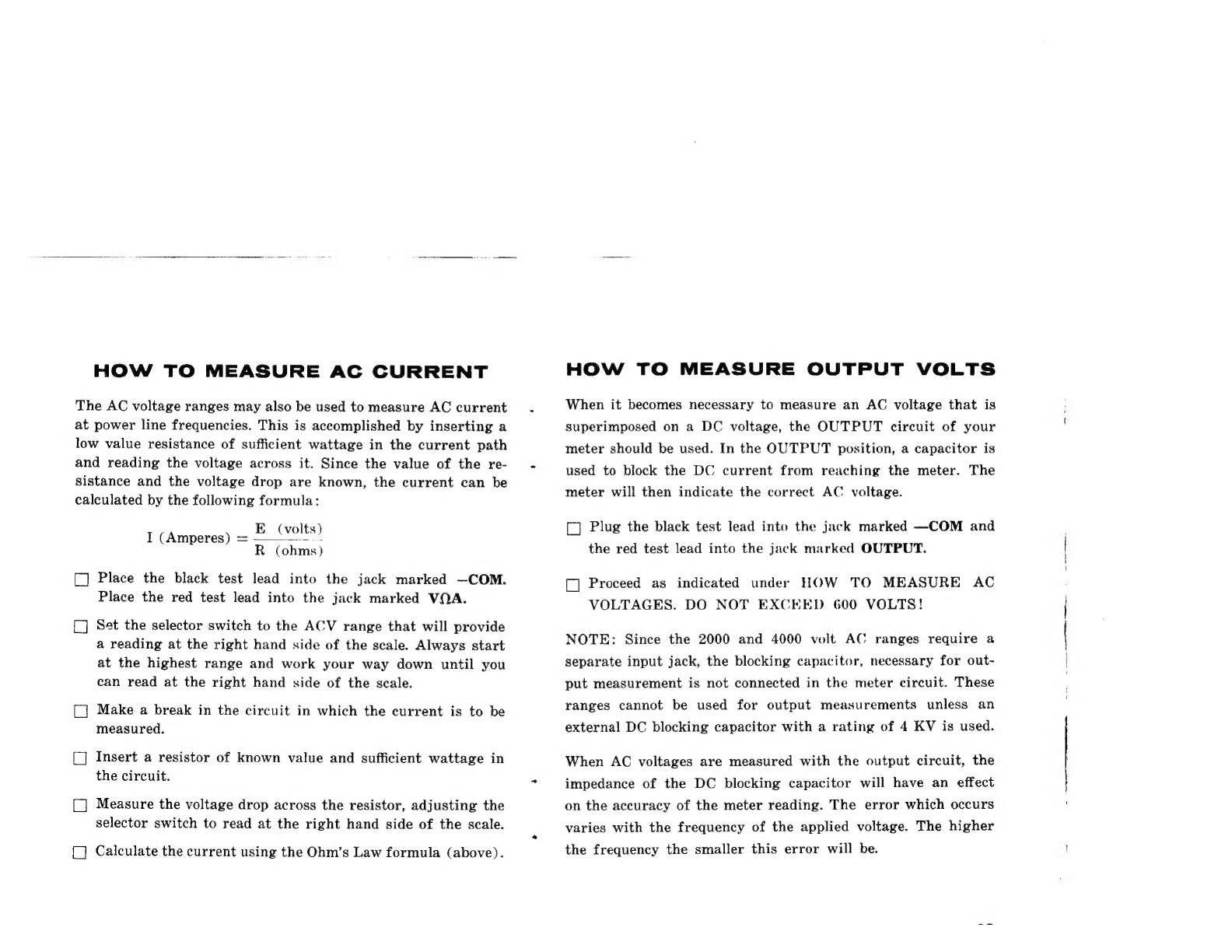
HOW
TO
MEASURE
AC
CURRENT
The
AC
voltage
ranges
may
also
be
used
to
measure
AC
current
at
power
line
frequencies.
This
is
accomplished
by
inserting
a
low
value
resistance
of
sufficient
wattage
in
the
current
path
and
reading
the
voltage
across
it.
Since
the
value
of
the
re-
sistance
and
the
voltage
drop
are
known,
the
current
can
be
calculated
by
the
following
formula:
E
(volts)
I
(Amperes)
=
-
R
(ohms)
[]
Place
the
black
test
lead into
the
jack
marked
—COM.
Place
the
red
test
lead
into
the
jack
marked
VOA.
[]
Set
the
selector
switch
to
the
ACV
range
that
will
provide
a
reading
at
the
right
hand
side
of
the
scale.
Always
start
at
the
highest
range
and
work
your
way
down
until
you
can
read
at
the
right
hand
side
of
the
scale.
[]
Make
a
break
in
the
circuit
in
which
the
current
is
to
be
measured.
[]
Insert
a
resistor
of
known
value
and
sufficient
wattage
in
the
circuit.
[]
Measure
the
voltage
drop
across
the
resistor,
adjusting
the
selector
switch
to
read
at
the
right
hand
side
of
the
scale.
[_]
Calculate
the
current
using
the
Ohm’s
Law
formula
(above).
HOW
TO
MEASURE
OUTPUT
VOLTS
When
it
becomes
necessary
to
measure
an
AC
voltage
that
is
superimposed
on
a
DC
voltage,
the
OUTPUT
circuit
of
your
meter
should
be
used.
In
the
OUTPUT
position,
a
capacitor
is
used
to
block
the
DC
current
from
reaching
the
meter.
The
meter
will
then
indicate
the
correct
AC
voltage.
((]
Plug
the
black
test
lead
into
the
jack
marked
—COM
and
the red
test
lead
into
the
jack
marked
OUTPUT.
[]
Proceed
as
indicated
under
HOW
TO
MEASURE
AC
VOLTAGES.
DO
NOT
EXCEED
600
VOLTS!
NOTE:
Since
the
2000
and
4000
volt
AC
ranges
require
a
separate
input
jack,
the
blocking
capacitor,
necessary
for
out-
put
measurement
is
not
connected
in
the
meter
circuit.
These
ranges
cannot
be
used
for
output
measurements
unless
an
external
DC
blocking
capacitor
with
a
rating
of
4
KV
is
used.
When
AC
voltages
are
measured
with
the
output
circuit,
the
impedance
of
the
DC
blocking
capacitor
will
have
an
effect
on
the
accuracy
of
the
meter
reading.
The
error
which
occurs
varies
with
the
frequency
of
the
applied
voltage.
The
higher
the
frequency
the
smaller
this
error
will
be.

HOW
TO
MEASURE
DB
(Decibles)
AC
output
voltages
are
often
measured
in
units
called
Decibels,
which
are
used
to
indicate
power
levels
in
amplifiers
or
general
telephone
work.
The
DB
scale
(bottom
meter
scale)
is
based
on
the
voltage
developed
across
a
600
ohm
line
when
.001
watt
is
dissipated.
This
voltage
is
assigned
the
reference
0
db.
Such
a
voltage
deflects
the
pointer
to
.775
volts
on
the
0-2
volt
AC
range.
Therefore,
a
direct
meter
reading
in
terms
of
deci-
bels
can
be
made
only
when
the
meter
is
connected
across
a
600-ohm
resistive
load.
Otherwise
only
relative
db
measure-
ments
can
be
obtained.
However,
in
a
large
number
of
cases,
relative
measurements
are
appropriate,
since
reference
con-
ditions
are
defined
by
other
factors
and
only
relative
variations
are
important.
To
measure
DB,
proceed
as
follows:
[]
Plug
the
black
test
lead into
the
jack
marked
—COM.
Plug
the
red
test
lead
into
the
jack
marked
OUTPUT.
NOTE:
When
no
DC
voltage
is
present,
the
VOA
jack
can
be
used
since
the
DC
blocking
capacitor
is
not
required.
(]
Rotate
the
selector
switch
to
the
highest
AC
range
and
work
down
to
one
which
will
provide
a
reading
at
the
right
hand
side
of
the
scale.
(]
Connect
the
test
leads
to
the
circuit
where
the
measurement
is
to
be
made.
[J
The
meter
pointer
will
indicate
a
reading
in
DB.
([]
The
final
DB
reading
is
determined
by
the
value
indicated
on
the
DB
scale
plus
the
addition
of
a
constant,
depending
on
the
range
setting.
The
following
table
will
give
you
the
constants
for
the
AC
ranges.
AC
VOLTAGE
RANGE
21
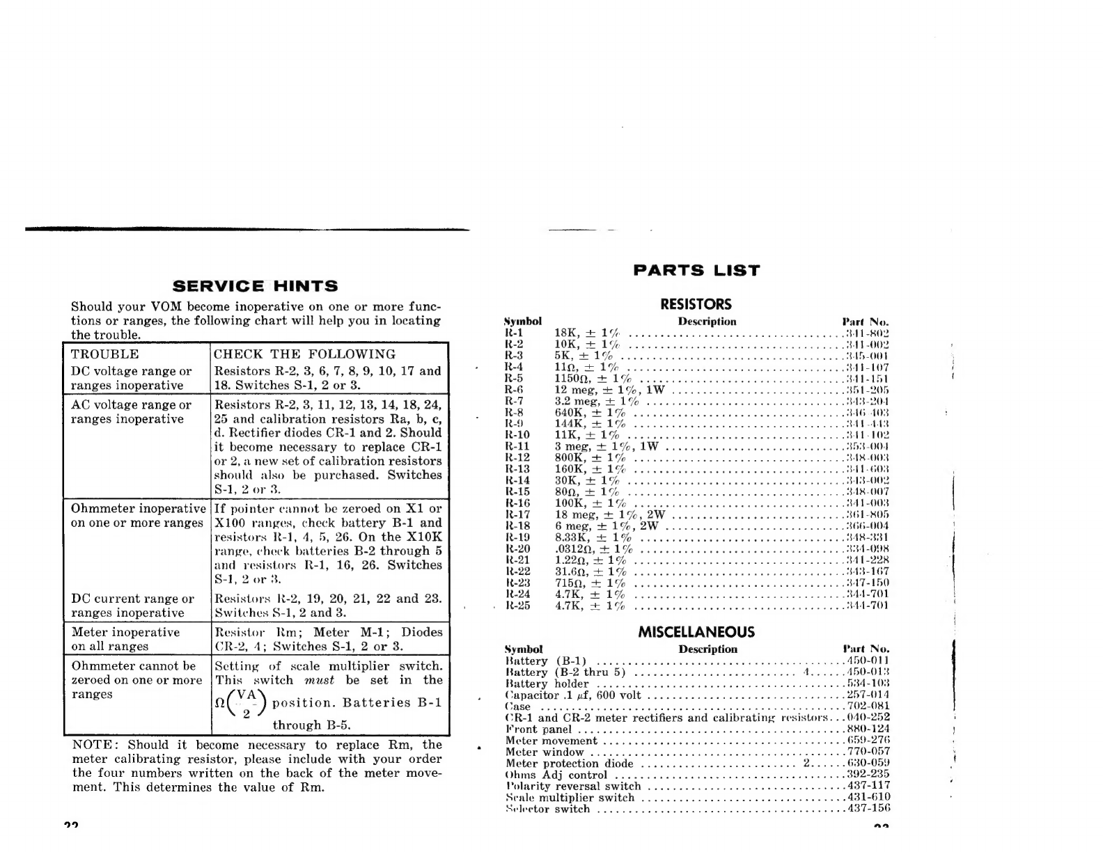
PARTS
LIST
SERVICE
HINTS
Should
your
VOM
become
inoperative
on
one
or
more
func-
RESISTORS
tions
or
ranges,
the
following
chart
will
help
you
in
locating
Symbol
Description
Part
No.
the
trouble.
R-1
TSK
EF
Gia
teh
taste
deed
ee
ota
whetaoe
fou
wes
oe
TEROR
R-2
TOKE
1G:
oo
etiin
cena
eien
Mensa
ade
i
bb
ol
eh
NTS002
TROUBLE
CHECK
THE
FOLLOWING
R-3
DK
ye
Las
cab
Se
cathe
beh
vA
wee
bo
Pa
wate
rece
IDLO]
DC
voltage
range
or
|Resistors
R-2,
8,
6,7,8,9,10,17and|
°°
RR
10,
EM
pees
esrececseteret
teeters
ee
ranges
inoperative
|18.
Switches
$-1,
2
or
8.
RG
12
meg,
ce
190,
4W
2s
AC
voltage
range
or
_|
Resistors
R-2,
3,
11,
12, 13,
14, 18,
24,
ae.
See
a4
Je
eS
Rie
een
a
ranges
inoperative
25
and
calibration
resistors
Ra,
b,
¢,
RO
PA
EO
wen
erehcec
wn
bee
ede
Ld
d.
Rectifier
diodes
CR-1
and
2.
Should
ReVO"
TUK
G6
hie
5
eo
etrtexe
eres
whoa
vie
venta
eee
oe
LET
OY
it
become
necessary
to
replace
CR-1
R-11
3
meg,
1%,
LW
oo.
cece
ccc
eee
ee
BI
S-
OO
or
2,
a
new
set
of
calibration
resistors
R-12
BOOK,
H
1G
occ
eee
eee
eee
ee
BAB
O08
°
etd
: :
R13
160K,
1%
ool
ee
eee
cece
eee
cent
nee
ee
al
11.602
should
also
be
purchased.
Switches
R14.
80K,
H1G
occ
ccc
cece
eee
BAS-008
S-1,
2
or
3.
BRAG
BOG
16
ce
acestas
hac
he
one
ow
pe
tabe
fy
am
ee
eee
ROUT
Ohmmeter
inoperative
jIf
pointer
cannot
be
zeroed
on
X1
or
ie
eee
POW
ote
Se
ee
Med
an
ge
Pie
pee
on
one
or
more
ranges
|X100
ranges,
check
battery
B-1
and
R-18
6
meg,
+
1%,
2W
.....
ccc
cece
cee
ee
seer
renee
s+
866-004
resistors
R-1,
4,
5,
26.
On
the
X10K
R-19
BBB
ET:
ioe
a
Stradi
eatin
spas
sees
eae
BABAR
range,
check
batteries
B-2
through
5
R-20
-038120,
mm
1%
arian
letseg
6
toi
wie
ete
ta:
1atah
orera.ne
iat
wera
ata are “aa
Wee
384-008
and
resistors
R-1,
16,
26.
Switches
oe
aes
in
Spee
ree
Rego
ie
SOE
a
matond
ae
8-1,
2
or
3.
ROR
TIBI,
10
yond
casset
sis
tncumaeatecsanasestotdiolo0
DC
current
range
or
|Resistors
R-2,
19,
20,
21,
22
and
23.
R-24
ATK
BAGO
os
oie
satin
evelers
any
sees
wee
eee
ee
BAT-TOL
2
:
ae
*
:
»
R-25
BK
Pe
DGG.
6
occas,
Scant,
ole
4
olathe
Gtaoh
aah
esc
oe
dr
CBee
344-701
ranges
inoperative
Switches
S-1,
2
and
3.
Meter
inoperative
Resistor
Rm;
Meter
M-1;
Diodes
MISCELLANEOUS
on
all
ranges
CR-2,
4;
Switches
8-1,
2
or
38.
Symbol
Description
Part
No.
Ohmmeter
cannot
be
|Sctting
of
scale
multiplier
switch.
Bate:
oe
nea'B)
SSRs
Bice
dite
als
oe
Bees
pt
Sane
thts
ee
fo
ae
zeroed
on
one
or
more
{This
switch
must
be
set
in
the
Battery
holder
......+.-.ccceeeeecceeeeesseeee
reese
++.
884-103
ranges
VA
ae
:
5
C
i
FD
E3600:
VOLE
fas
ceed
creda
g5
aig
wiays
QecietenY
eeaee
257-014
-
a
‘)
position.
Batteries
B-1
Cae
aad
hee
yas
fered
a
leshahctal
aie
Warr
bem
estes
702-081
2
CR-1
and
CR-2
meter
rectifiers
and
calibrating:
resistors.
..040-252
through
B-5.
Wront:
DRTC!’
4.04
ccncaghdudaseawen
piece
seuss
Gasudedbas
wad
880-124
NOTE:
Should
it
become
necessary
to
replace
Rm,
the
2
Meter
Movement
.
1.0...
eee
eee
eee
eee
ees
659-276
:
. A
:
Meter:
wind
Ow
oui.
ee
ccaie
cede
v
ote
eae
ie
ee
tah
todas
770-057
meter
calibrating
resistor,
please
include
with
your
order
Meter
protection
diode
............0
0c
ee
eee
eeee
Daren
ee
630-059
the
four
numbers
written
on
the
back
of
the
meter
move-
Ohms.Adj,
control’
(5
:226
60.466
eek
Pere
ne
teeny
cone
at
392-235
ment.
This
determines
the
value
of
Rm.
Polarity
reversal
switch
.2
0.66
626
aie
eesti
ce
eee
eek
tees
437-117
Seale
multiplier
switch
........
02.0...
2
2c
eee
eee
een
431-610
Selector
Switeh:
Sc/0c6
4
a.
eave
auieasd
oh
te
aod
a
Whe
bar
oud
oa
ard
Sle
gun
oe
wie
eer
437-156
9
aa
Other Allied Radio Test Equipment manuals


