manuals.online logo
Brands
  1. Home
  2. •
  3. Brands
  4. •
  5. Micsig
  6. •
  7. Test Equipment
  8. •
  9. Micsig RCP Series User manual

Micsig RCP Series User manual

Operation steps
1) Connect to the oscilloscope: Set the oscilloscope input impedance to 1MΩ, connect
the probe BNC end to oscilloscope (make sure the oscilloscope is properly grounded);
2) Power the probe: Use standard adapter to power the probe. Indicator light turns green
after power on;
3) Connect the DUT: make sure that the coil plug is inserted in place and the wire or pin
under test passes through the appropriate position of the coil.
4) Power up the DUT.
5) After test, disconnect the circuit first, then unplug the coil.
6) Disconnect probe power.
Warranty
1) Micsig warrants the main body of this current probe for 1 year.
During the warranty period, Micsig will be responsible for free maintenance for any
failure caused by the quality of the product under normal use.
2) Under the following circumstances, Micsig will refuse to provide maintenance services
or charge for a fee:
a. No packaging or anti-counterfeiting label.
b. Anti-counterfeit label has been altered or blurred beyond recognition.
c. Unauthorized disassembly, such as: changing wires, dismantling internal
components, etc.
d.No sales voucher or the content of sales voucher does not match the product.
Safety Precautions
※Please use within safe voltage range.
※The equipment connected to the probe must be reliably grounded.
※The outer skin of the Rogowski coil should be inspected before use. If it is damaged,
stop using it.
※Before connecting the probe to the circuit under test, make sure the circuit under
test is turned off.
※Please use the adapter that comes standard with the probe.
Rogowski AC Current Probe -- RCP series
Quick Guide
Overview
The RCP series Rogowski current probe measures AC currents up to
600Apk, max. bandwidth up to 30 MHz, delivers 1% typical accuracy, able
to measure high-frequency, large current signals easily and accurately.
A 1.6mm thin, flexible, clip-around Rogowski coil allow user to conduct
measurements without damaging the conductor and have no interference
to the DUT.
Shenzhen Micsig Technology Co., Ltd.
Tel: +86-755-88600880 Email: [email protected]om
Add: A106, Huafeng Robot Industrial Park, Hangcheng Rd, Bao’an, Shenzhen, Guangdong,
China, 518126
* Country specific adapter plug
Specifications
Model
RCP300
RCP600
Bandwidth
10Hz-30MHz
10Hz-30MHz
Measurement range
200mApk-300Apk
200mApk-600Apk
Output sensitivity
20mV/A(50X)
10mV/A(100X)
Accuracy (typical)
1%
1%
Output noise
<
18mVpp
<
12mVpp
Output interface
BNC
Peak di/dt
20kA/μs
40kA/μs
Droop
9%/ms
6%/ms
Effect of conductor
position
Within ±1% (deviation from center part)
Offset voltage
<±1mV
Peak coil isolation voltage
AC 2kVrms (1 min) (50Hz/60Hz) ( Rogowski coil part only )
Output impedance
High impedance
Measurable conductor
diameter
≤20mm
Power supply
DC 12V
Integrator size
70*40*17mm
Wire length (integrator
to Rogowski coil)
1.5m(customizable)
Coil inner diameter
25mm(customizable)
Coil circumference
80mm(customizable)
Coil cross-section
diameter
Appx. 1.6mm
Interface
1MΩ BNC
Environment
Working temperature
Base unit : 0℃- 55℃Coil : -20℃- 125℃
Storage temperature
-30
℃
-70
℃
Working humidity
≤85%RH
Storage humidity
≤90%RH
Appearance
The RCP series current probe are composed of two parts: Integrator and Rogowski coil.
1.
Output
:
Standard BNC, compatible with all BNC oscilloscopes.
2.
Power supply: DC 12V, adapter
3.
Power indicator: Turn Green after powered on.
4.
Cable length: 1.5m,from integrator to coil, customizable.
5.
Rogowski coil inner diameter: 25mm, measures wires within 20mm in diameter.
6.
Rogowski coil cross-section diameter: 1.6mm
7.
Rogowski coil circumference: 80mm, customizable.
8.
Current direction: When the current flows in the marked direction, the output is
positive, otherwise it is negative.
Precautions
※to ensure accuracy, the wire being measured should be positioned
as much as possible between X and Y in the right diagram, where
X is the center of coil and Y is the midpoint of the coil circumference.
※to ensure accuracy, the wire should avoid the coil junction as
much as possible during measurement (shadow area).
※try to stay away from strong magnetic field interference sources as
much as possible to avoid measurement errors.
※the coil can be placed around the wire being measured to measure
the interference signals in the surrounding area, to determine
whether there is strong interference nearby.
7
5
8
6
1
4
3
2
Y
open direction

This manual suits for next models

2

Other Micsig Test Equipment manuals

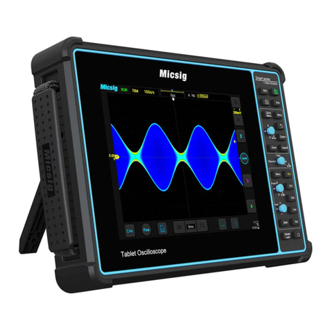
Micsig MDP Series User manual

Micsig

Micsig MDP Series User manual

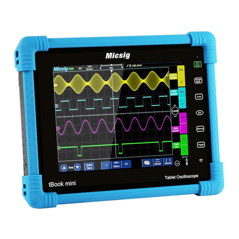
Micsig tbook mini Series User manual

Micsig

Micsig tbook mini Series User manual

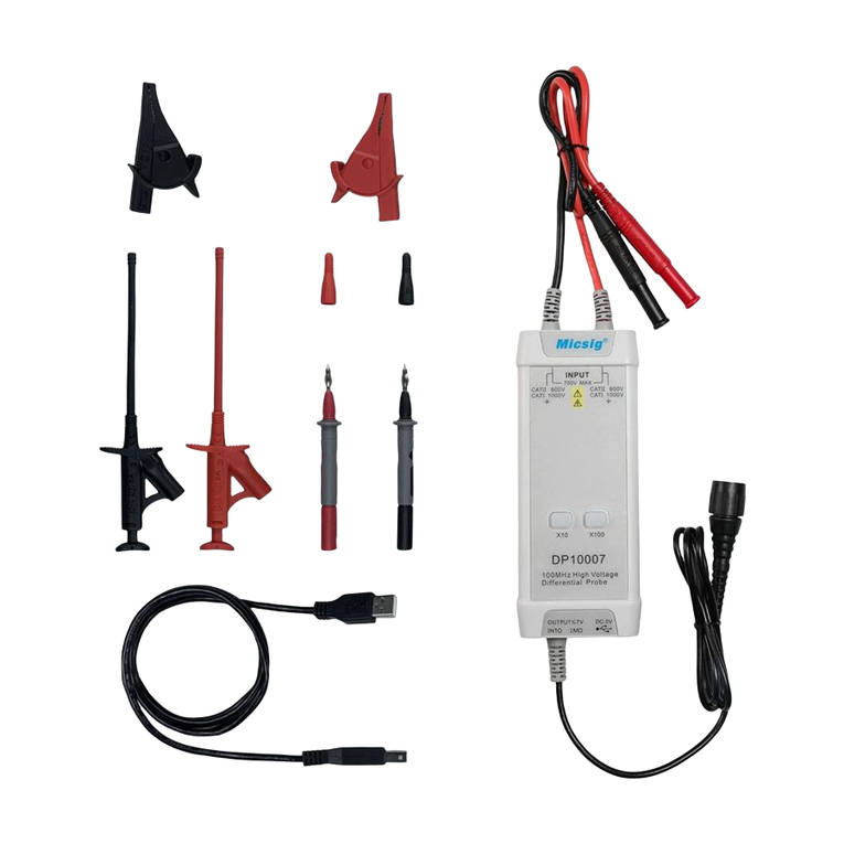
Micsig DP10007 User manual

Micsig

Micsig DP10007 User manual

Micsig ATO Series User manual

Micsig

Micsig ATO Series User manual

Micsig MS200 Series User manual

Micsig

Micsig MS200 Series User manual

Micsig CP2100A User manual

Micsig

Micsig CP2100A User manual

Micsig SATO1000 Series User manual

Micsig

Micsig SATO1000 Series User manual

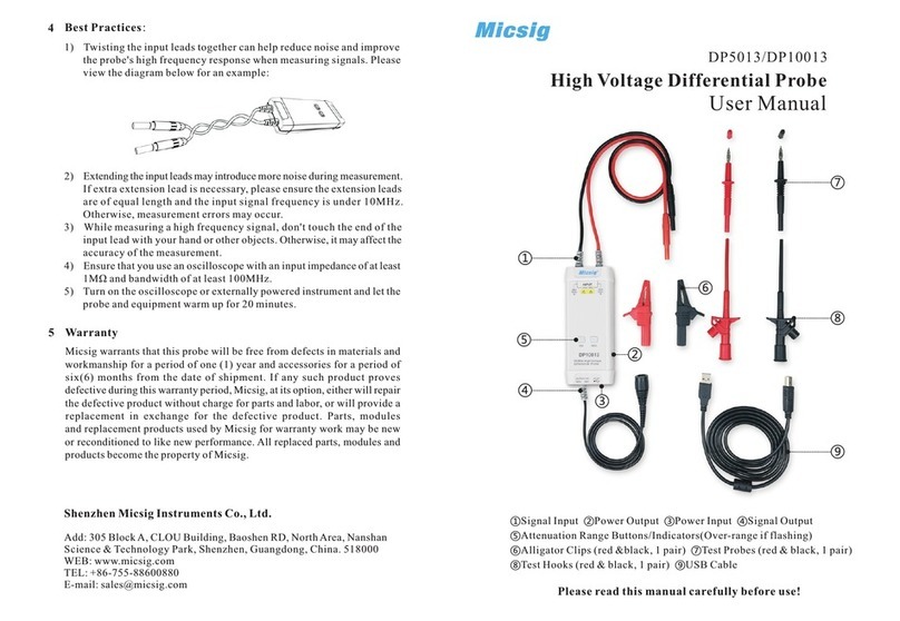
Micsig DP5013 User manual

Micsig

Micsig DP5013 User manual

Micsig DP750 User manual

Micsig

Micsig DP750 User manual

Micsig SigOFIT MOIP01P SigOFIT MOIP01P User manual

Micsig

Micsig SigOFIT MOIP01P SigOFIT MOIP01P User manual

Micsig MS300 Series User manual

Micsig

Micsig MS300 Series User manual

Micsig Smart Series User manual

Micsig

Micsig Smart Series User manual

Micsig VATO Series User manual

Micsig

Micsig VATO Series User manual
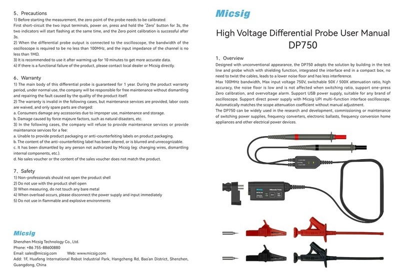
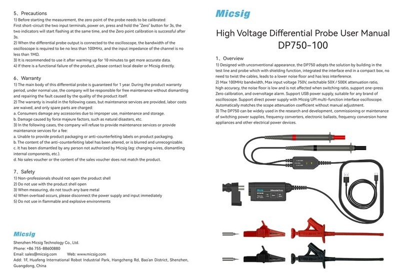
Micsig DP750-100 User manual

Micsig

Micsig DP750-100 User manual
Micsig ATO1000 Series User manual

Micsig

Micsig ATO1000 Series User manual

Popular Test Equipment manuals by other brands

Teledyne FST-040 manual

Teledyne

Teledyne FST-040 manual

A&D PT Series instruction manual

A&D

A&D PT Series instruction manual

YOKOGAWA 30031A user manual

YOKOGAWA

YOKOGAWA 30031A user manual

WHALETEQ MECG 2.0 user manual

WHALETEQ

WHALETEQ MECG 2.0 user manual

Noyes SMLP 5-5 user guide

Noyes

Noyes SMLP 5-5 user guide

GJD D-TECT X GJD394 quick start guide

GJD

GJD D-TECT X GJD394 quick start guide

STATICO S2114 Product information / User manual

STATICO

STATICO S2114 Product information / User manual

Megger MFT1741 user guide

Megger

Megger MFT1741 user guide

PCE Health and Fitness PCE-IC1 manual

PCE Health and Fitness

PCE Health and Fitness PCE-IC1 manual

Hioki 3541 instruction manual

Hioki

Hioki 3541 instruction manual

Mark-10 TT01 series quick start guide

Mark-10

Mark-10 TT01 series quick start guide

Allied Radio Knight KG-640 Operator's manual

Allied Radio

Allied Radio Knight KG-640 Operator's manual

M-system Mini-M M2PHS2 instruction manual

M-system

M-system Mini-M M2PHS2 instruction manual

DoorKing 1514-130 manual

DoorKing

DoorKing 1514-130 manual

FSM DPC user manual

FSM

FSM DPC user manual

ChemInstruments COF-1000 operating instructions

ChemInstruments

ChemInstruments COF-1000 operating instructions

Sunrise telecom CaLan N1776A user manual

Sunrise telecom

Sunrise telecom CaLan N1776A user manual

Lifeloc FC10Plus Operation manual

Lifeloc

Lifeloc FC10Plus Operation manual

manuals.online logo
manuals.online logoBrands
  • About & Mission
  • Contact us
  • Privacy Policy
  • Terms and Conditions

Copyright 2025 Manuals.Online. All Rights Reserved.