B 45-015, REV. 9/21
• Always carry cylindrically shaped loads in the vertical
position, not the horizontal.
• Always clamp loads with the contact pads, if appli-
cable, not the arm or arm base.
• Never rotate a load that is off center to the centerline
of rotation. Severe damage to the rotator could result.
• Always ensure that the load is the same width as the
pallet and neatly stacked when using a carton clamp.
3.13 Load Positioning
• Be accurate in load placement. It’s important to know
what the load will do when it’s released.
• Always carry loads as close to the floor as possible,
consistent with the surface being traversed. Scraping
or bumping the floor surface with the load or the
attachment can severely damage the attachment and
cause product damage. The mast should be tilted
back.
• Always keep the load positioned as close as possible
to the horizontal center of the lift truck.
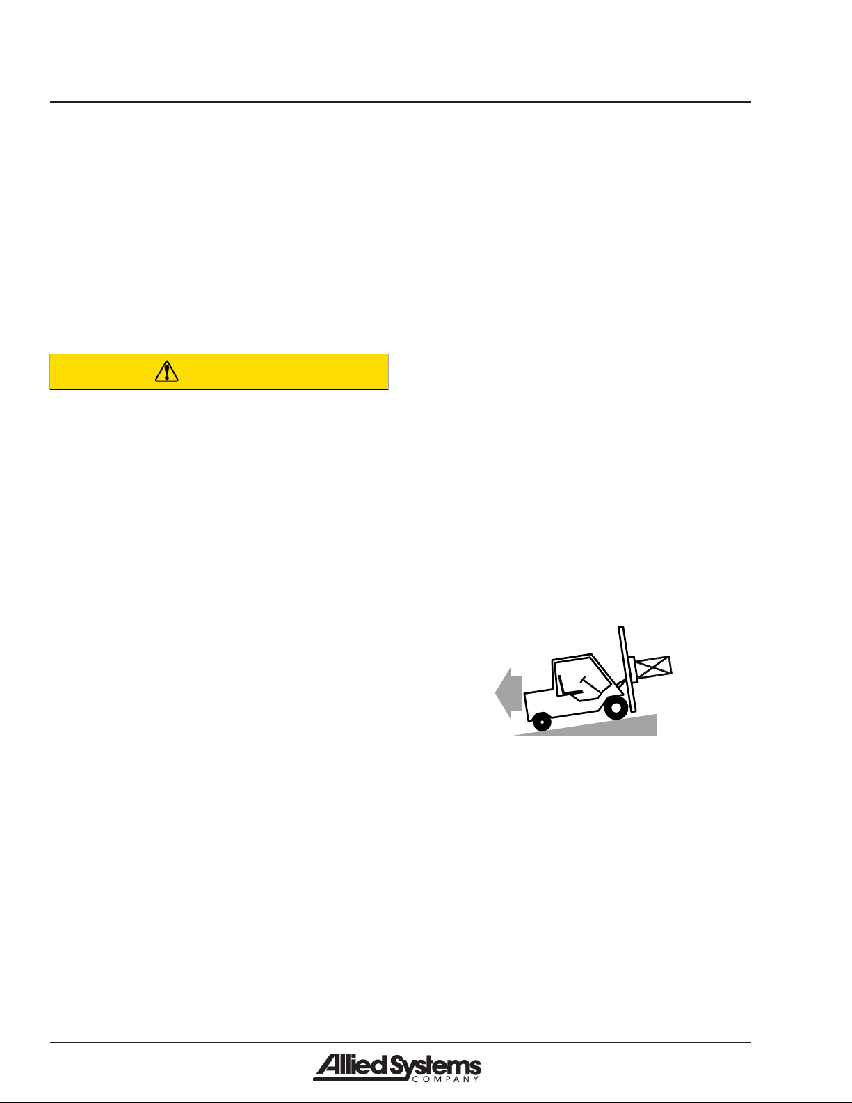
• Always back down ramps or inclines. Driving forward
down a ramp or incline with a clamped load will
lessen the stability of the truck. (Figure 3-4)
Figure 3-4
• Do not cross dock boards or dock levelers with the
attachment or carriage fully lowered. Ramming the
front or rear of the attachment against a dock board
can cause severe damage.
• Limit lift truck movement to a minimum when high
stacking. Limit sideshift movement to a minimum
when high stacking.
• Always be observant when high stacking. Look for
poorly stacked loads, overhead obstacles, broken
cartons, or damaged products in the stack.
• Travel slowly around corners. Sound horn on blind
corners. Be careful of tail swing and overhead clear-
ances. Watch in all directions. Avoid sudden stops.
• Before disconnecting hydraulic lines, be sure to lower
all loads and relieve all hydraulic pressure. The load
could fall on you, or escaping hydraulic oil could
cause severe personal injury.
• Prevent personal injury or equipment damage by
using a lifting device with a lifting capacity greater
than twice the weight of any equipment to be lifted.
3.12 Load Handling
• Treat an unloaded forklift with an attachment as
partially loaded.
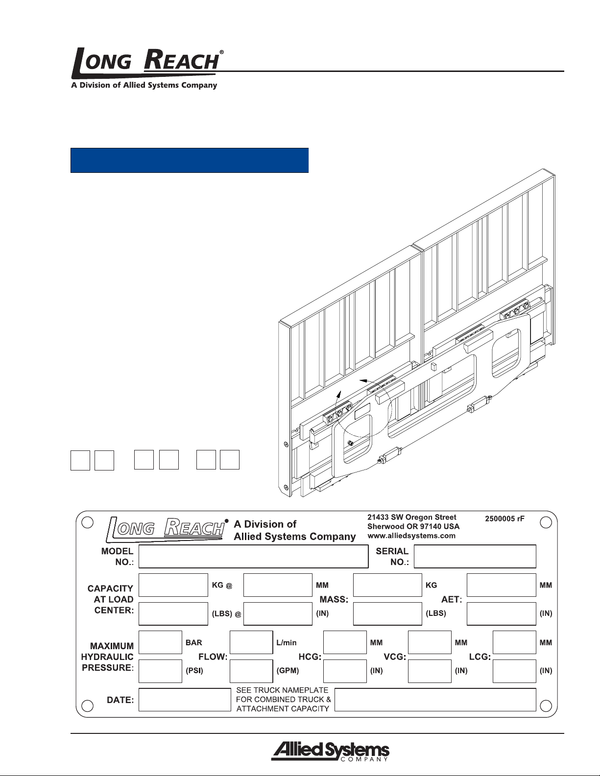
CAUTION
Equipment overload hazard.
Injury or equipment damage may result if
the capacity of the truck and attachment
combined are less than the attachment
capacity.
Consult truck nameplate for truck
capacity with an attachment installed.
• Never overload the attachment. Refer to the attach-
ment nameplate for the rated capacity of the
attachment. Refer to the truck nameplate for the
maximum net working capacity of the truck/attach-
ment combination. Never use a load to support or
move another object. Doing so can easily exceed the
holding capacity of the attachment.
• Always check loads to be handled. Correct loads that
are broken, unbalanced, loose, or too heavy.
• Never lift, lower, side shift, pivot, rotate, or tilt loads
while traveling. Repositioning loads while traveling
affects the stability of the truck and may impede
vision or clearances.
• Do not use an attachment to open or close boxcar
doors. Doing so can severely damage the attachment
and cause loss of warranty. Damage to clamp arms
may result in product damage.
• Do not carry loose items or unsupported loads on
top of a clamped load.
• Never use chains, cables, or other devices in conjunc-
tion with an attachment for load handling.
• Never clamp loads other than what the attachment
was designed to handle.