Allied Systems LONG REACH CR Series Manual

REV. 04/2245-022
Installation, Maintenance
and Service Manual
CR
Series Rotators

45-022 REV. 04/22
TABLE OF CONTENTS
SECTION 1 NAMEPLATE LOCATION ........ 3
SECTION 2 MODEL IDENTIFICATION ....... 4
SECTION 3 SAFETY SUMMARY................ 5
3.1 Safety Information .......................... 5
3.2 Safety Regulations ......................... 5
3.3 Safety Symbols............................... 5
3.4 Labeling.......................................... 6
3.5 Training ........................................... 6
3.6 Personnel Safety ............................ 7
3.7 Pre-start Checks............................. 8
3.8 Operation Warnings........................ 8
3.9 Hydraulic Hazards ......................... 8
3.10 Electrical Hazards......................... 9
3.11 Maintenance Warnings ................. 9
3.12 Load Handling .............................10
3.13 Load Positioning ..........................11
3.14 Operator’s Controls .....................12
3.15 Clamp Open Control....................13
3.16 Industry Standards ......................13
SECTION 4 INSTALLATION PROCEDURE 15
4.1 Truck Requirements.......................15
4.2 Attachment Installation ..................15
4.3 Hydraulic Connections...................18
4.4 Third Hook Welding Instructions ...19
4.5 Fork Installation ............................ 20
SECTION 5 OPERATION............................ 22
SECTION 6 SERVICE PROCEDURE......... 23
6.1 General.......................................... 23
6.2 Attachment Removal...................... 23
6.3 Pinion/Ring Gear and Bearing....... 24
6.4 Bearing Seal Replacement............ 25
6.5 Oil-Filled Gearboxes...................... 26
6.6 Grease-Filled Gearboxes .............. 31
6.7 Motor Disassembly ........................ 38
6.8 Motor Assembly ............................. 42
6.9 Reusable Hose Fittings.................. 49
6.9.1 Remove Fitting............................ 49
6.9.2 Fitting Assembly.......................... 50
6.10 Torque Specifications................... 51
SECTION 7 MAINTENANCE ...................... 52
7.1 Schedule ........................................ 52

45-022 REV. 04/22 3
SECTION 1 NAMEPLATE LOCATION
A
A
NOTICE
When you receive your attachment, locate the Long
Reach nameplate (upper left corner on the body). Record
the information from the nameplate, along with the date
received, at the bottom of this page.
If the nameplate is missing, look for the serial number
stamped directly into the metal at the nameplate location
and consult the factory for details.
- -
Date Received:

45-022 REV. 04/22
4
SECTION 2 MODEL IDENTIFICATION
Each attachment is identified by a model number and a serial number located on the
nameplate attached to the unit prior to shipment. Long Reach’s model numbers are
designed to describe how an attachment is equipped. The guide below illustrates the
information that is represented in an multi-digit model number. Always include model
and serial number when ordering parts or requesting service information.
CR Series Model Number:
C R A 3 5 23 F N EO N OO N 0A N
SERIES
CRA, CRB,
CRC, CRD =
Rotator, 360
degrees
CAPACITY
@ 24” load center
12 = 12,500 lbs
35 = 3,500 lbs
30 = 30,000 lbs
55 = 5,500 lbs
65 = 6,500 lbs
70 = 7,000 lbs
90 = 9,000 lbs
24 = 24,000 lbs
@ 30” load center
FORK BAR
WIDTH
32 = 32"
33 = 33”
35 = 35”
37 = 37”
42 = 42”
45 = 45”
48 = 48”
60 = 60”
61 = 61”
84 = 84”
NB = No fork
bars provided
ROTATOR
FORK SIZE
Example: FB442 =
1.5” X 4”W X 42”L
FB = 1.5”
FC = 1.75”
FD = 2.0”
FF = 2.5”
FNONE = No forks
provided
OPTION
ONO = Standard, no options
C02 = High efficiency motor
C25 = H15 + S72
C28 = High heat package, center lock & relo-
cated valve
H03 = Includes single relief valve installed
H15 = LH hyd termination
S13 = Full taper, polished forks
S18 = Special forks; top/bottom taper, top
polish, hard surface on bottom leading
edge
S22 = Special notching on top fork bar
S57 = Foundry package
S61 = Marine paint
S72 = Cascade knob-style fork latch
MOUNTING TYPE & ANGLE
AN0 = Class II, 0° w/bolt-on lower hooks
AQ0 = Class II, 0° w/quick hook group
BN0 = Class III, 0~ bolt-on lower hooks
BN4 = Class III, 4~ bolt-on lower hooks
BQ0 = Class III, 0~ quick hook group
CN0 = Class IV, 0° w/bolt-on lower hooks
NNN = No mounting group included
S2E = Mounting to fit Cat 930M integrated tool handler
S71 = Mounting to fit Cat 930H integrated tool handler
S88 = Mounting to fit John Deere 482C

45-022 REV. 04/22 5
SECTION 3 SAFETY SUMMARY
3.1 Safety Information
Safety is Everyone’s Responsibility
Whether you are new on the job or a seasoned veteran, these safety tips may prevent
injury to you, to others, or to the materials you are handling. Always be alert, watch out
for others, and follow these suggestions:
Attachments handle material, not people.
Safety starts with common sense, good judgement,
properly maintained equipment, careful operation, and
properly trained operators.
The safety instructions and warnings, as documented in this manual and shipped with the
machine, provide the most reliable procedures for the safe operation and maintenance
of your Long Reach attachment. It’s your responsibility to see that they are carried out.
3.2 Safety Regulations
Know your company’s safety rules. Some companies have site-specific directions and
procedures. The methods outlined in your operator’s manual provide a basis for safe oper-
ation of the machine. Because of special conditions, your company’s material handling
procedures may be somewhat different from those shown in this manual.
3.3 Safety Symbols
The following terms define the various precautions and notices:
DANGER
Indicates a hazardous situation which, if not avoided,
will result in death or serious injury. Carefully read the
message that follows to prevent serious injury or death.
WARNING
Indicates a hazardous situation which, if not avoided, could
result in death or serious injury. Carefully read the message
that follows to prevent serious injury or death.

45-022 REV. 04/22
6
CAUTION
Indicates a hazardous situation which, if not avoided, could
result in minor or moderate injury, or equipment damage or
void the machine warranty. Carefully read the message that
follows to prevent minor or moderate injury.
NOTICE
Describes information that is useful but not safety related.
WARNING
Multiple hazards.
Ignoring safety warnings may cause equipment damage,
personal injury or death.
All possible safety hazards cannot be foreseen and
included in this manual. The operator must always be
alert to possible hazards that could endanger personnel
or damage the equipment.
3.4 Labeling
• Change capacity, operation, and maintenance instruction plates, tags, or decals when
a forklift truck is equipped with an attachment. If the truck is equipped with front-end
attachments other than factory installed attachments, truck must be marked to iden-
tify the attachments and show the approximate weight of the truck and attachment
combination at maximum elevation with load laterally centered.
3.5 Training
• Make sure all operators are trained in the fork and attachment adaptation, operation,
and use limitations. Retrain an operator if a new attachment is added to the forklift.
Consult the operator’s manual for instructions on how to use the new equipment.
• Know the mechanical limitations of your forklift.
• Modifications or additions that affect capacity or safe operation must have prior written
approval from the forklift truck manufacturer. Capacity, operation, and maintenance
instruction plates, tags, or decals shall be changed accordingly.
• Never use free rigging for a below-the-forks lift. It could affect the capacity and safe
operation of a lift truck.

45-022 REV. 04/22 7
3.6 Personnel Safety
• When removing or installing dismountable attachments always keep hands and feet
free from dangerous positions or pinch points. Never leave a dismounted attachment
in a dangerous position.
• Keep hands, feet, long hair and clothing away from power-driven parts. Do not wear
loose fitting clothing or jewelry while performing maintenance and lubrication in these
areas.
• Never jump on or off the machine.
• Never stand on top of material being raised, lowered, or transported. (Figure 3-1)
• Never use the attachment or its load to support a man-carrying device.
• Never allow anyone under a load or under the carriage. (Figure 3-2)
• Never stand in front of or beside an attachment that is being operated. Never allow
another person to approach an attachment that is being operated. (Figure 3-3)
• Never leave an attachment or load in an elevated position.
• Never reach through the mast of the truck. Keep all parts of the body within the
driver’s compartment.
• Always operate an attachment from the operator’s seat, never while standing next
to the lift truck.
• Do not allow riders on the truck at any time.
• Always use reverse when carrying a load that impedes full vision. Watch for pedes-
trians when transporting.
• Always use personal protective equipment (PPE) appropriate to the situation.
Figure 3-1, Figure 3-2,
Figure 3-3,

45-022 REV. 04/22
8
3.9 Hydraulic Hazards
DANGER
Injection hazard.
Infection and gangrene will result when hydraulic oil
penetrates the skin. See a doctor immediately to prevent
loss of limb or death.
Use a piece of cardboard to check for hydraulic leaks.
• Wear personal protective equipment, such as gloves and safety glasses, whenever
servicing or checking a hydraulic system.
• Assume that all hydraulic hoses and components are pressurized. Relieve all hydraulic
pressure before disconnecting any hydraulic line.
• Never try to stop or check for a hydraulic leak with any part of your body; use a piece
of cardboard to check for hydraulic leaks.
3.7 Pre-start Checks
• Check your equipment before you operate it. If anything looks wrong, unusual or
different, report it before using the attachment.
• Do not operate this machine if you know of malfunctions, missing parts, and/or
mis-adjustments. These situations can cause or contribute to an accident or damage
to the machine. Stop the machine immediately if problems arise after starting.
• Check to make sure the attachment on your truck is the same as on the truck
capacity plate.
• Check for hydraulic leaks and cracked hoses or fittings. Check the hydraulic oil level
in the lift truck hydraulic reservoir.
• All electrical cables and connectors must be in good condition. Use caution in wet
weather to avoid danger from electrical shock.
• Always check the attachment for proper fit and engagement of the truck carriage.
3.8 Operation Warnings
• You must be trained to operate this equipment prior to operation. Be extremely careful
if you do not normally operate this machine. Reorient yourself to the machine before
starting, then proceed slowly.
• Always operate an attachment from the driver’s seat.
• Always lower the attachment if you need to leave the lift truck. A lift truck supporting
a load requires your full attention.

45-022 REV. 04/22 9
3.11 Maintenance Warnings
Maintenance, lubrication and repair of this machine can be dangerous unless performed
properly. You must have the necessary skills and information, proper tools and equip-
ment. Work in a method that is safe, correct, and meets your company’s requirements.
• Do not attempt to make adjustments, or perform maintenance or service unless you
are authorized and qualified to do so.
• Include attachments in a scheduled maintenance and inspection program. Tailor
inspection steps to the attachment.
• Unless specified in service procedures, never attempt maintenance or lubrication
procedures while the machine is moving or the engine is running.
• Always perform all maintenance and lubrication procedures with the machine on level
ground, parked away from traffic lanes.
NOTICE
Local laws and regulations may require that additional
safety measures be taken.
• Never rely on the hydraulic system to support any part of the machine during main-
tenance or lubrication. Never stand under a component that is supported only by the
hydraulics. Make sure it is resting on its mechanical stops or appropriate safety stands.
• Use caution when working around hot fluids. Always allow lubricating and hydraulic
oils to cool before draining. Burns can be severe.
• Use extreme caution when using compressed air to blow parts dry. The pressure
should not exceed 30 psi (208 kPa) at the nozzle. Never use compressed air on
yourself. Air pressure penetrating your skin can be fatal.
3.10 Electrical Hazards
WARNING
Electrocution hazard.
Contact with energized equipment may result in injury or
death and will damage equipment.
Remain at least 25 feet from high voltage electrical wires.
• All electrical cables and connectors must be in good condition (free of corrosion,
damage, etc). Use caution in wet weather to avoid danger from electrical shock.
Never attempt electrical testing or repair while standing in water.
• Do not wear electrically conductive jewelry, clothing, or other items while working
on the electrical system.

45-022 REV. 04/22
10
3.12 Load Handling
• Treat an unloaded forklift with an attachment as partially loaded.
CAUTION
Equipment overload hazard.
Injury or equipment damage may result if the capacity
of the truck and attachment combined are less than the
attachment capacity.
Consult truck nameplate for truck capacity with an
attachment installed.
• Never overload the attachment. Refer to the attachment nameplate for the rated
capacity of the attachment. Refer to the truck nameplate for the maximum net working
capacity of the truck/attachment combination. Never use a load to support or move
another object. Doing so can easily exceed the holding capacity of the attachment.
• Always check loads to be handled. Correct loads that are broken, unbalanced, loose,
or too heavy.
• Never lift, lower, side shift, pivot, rotate, or tilt loads while traveling. Repositioning loads
while traveling affects the stability of the truck and may impede vision or clearances.
• Do not use an attachment to open or close boxcar doors. Doing so can severely
damage the attachment and cause loss of warranty. Damage to clamp arms may
result in product damage.
• Do not carry loose items or unsupported loads on top of a clamped load.
• Never use chains, cables, or other devices in conjunction with an attachment for
load handling.
WARNING
Suffocation hazard.
Engine exhaust fumes can cause death.
Remove the exhaust fumes from the area with an exhaust
pipe extension, or use ventilation fans and open shop
doors to provide adequate ventilation.
• Before disconnecting hydraulic lines, be sure to lower all loads and relieve all hydraulic
pressure. The load could fall on you, or escaping hydraulic oil could cause severe
personal injury.
• Prevent personal injury or equipment damage by using a lifting device with a lifting
capacity greater than twice the weight of any equipment to be lifted.

45-022 REV. 04/22 11
3.13 Load Positioning
• Be accurate in load placement. It’s important to know what the load will do when
it’s released.
• Always carry loads as close to the floor as possible, consistent with the surface being
traversed. Scraping or bumping the floor surface with the load or the attachment can
severely damage the attachment and cause product damage. The mast should be
tilted back.
• Always keep the load positioned as close as possible to the horizontal center of the
lift truck.
• Always back down ramps or inclines. Driving forward down a ramp or incline with a
clamped load will lessen the stability of the truck. (Figure 3-4)
Figure 3-4,
• Do not cross dock boards or dock levelers with the attachment or carriage fully
lowered. Ramming the front or rear of the attachment against a dock board can
cause severe damage.
• Limit lift truck movement to a minimum when high stacking. Limit sideshift movement
to a minimum when high stacking.
• Always be observant when high stacking. Look for poorly stacked loads, overhead
obstacles, broken cartons, or damaged products in the stack.
• Travel slowly around corners. Sound horn on blind corners. Be careful of tail swing
and overhead clearances. Watch in all directions. Avoid sudden stops.
• Never clamp loads other than what the attachment was designed to handle.
• Always carry cylindrically shaped loads in the vertical position, not the horizontal.
• Always clamp loads with the contact pads, if applicable, not the arm or arm base.
• Never rotate a load that is off center to the centerline of rotation. Severe damage to
the rotator could result.
• Always ensure that the load is the same width as the pallet and neatly stacked when
using a carton clamp.
45-022 REV. 04/22
12
3.14 Operator’s Controls
Some lift trucks are equipped with a single lever to control both hoist and tilt functions,
others have separate levers for each function. Refer to your lift truck manual for more
information.
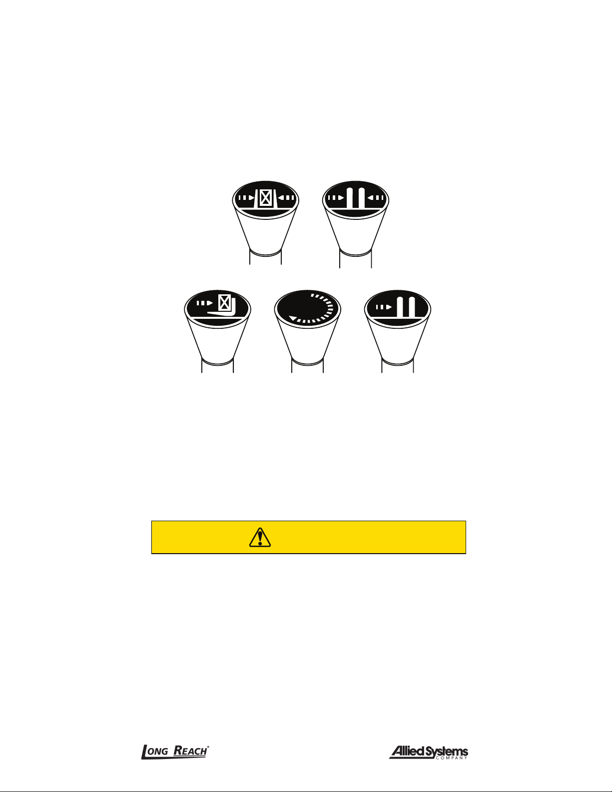
For clarity, the direction of arm movement is shown on the control handle. To move the
arms in the direction shown, pull the handle towards the operator. To move the arms in
the opposite direction, the push the handle away from the operator. (Figure 3-5)
Clamp Fork position
Push/pull Rotate Sideshift
Figure 3-5, Operator controls
Lifting speed is controlled by the speed of the engine and the position of the control
lever. Engine speed has no effect on lowering speed.
Before going on the job, shift the truck control levers one way and then the other to
determine which direction the attachment moves when the levers are shifted. Make sure
the attachment moves smoothly throughout its travel, without binding or pinching hoses.
CAUTION
Equipment damage hazard.
Injury or equipment damage may result if the attachment
does NOT operate smoothly.
Do not take malfunctioning equipment on the job. Check
with your supervisor about needed repairs.

45-022 REV. 04/22 13
3.15 Clamp Open Control
Effective October 7, 2010, safety standard ANSI/ITSDF B56.1, Section 7.25.7 covers all lift
trucks with a load bearing clamp (paper roll clamp, carton clamp, etc.), and requires the
driver to make two distinct motions before opening or releasing the clamp. For example,
you must press a switch and then move a lever to unclamp the load. This requirement
applies to new and used attachments being mounted on trucks which shipped from the
factory after October 7, 2010, and is a recommended feature to be installed on dealer
orders and existing applications
3.16 Industry Standards
ANSI/ITSDF B56.1-2016 is the published sequence and direction standard for lever and
hand-type controls.
NOTICE
The chart on the following page shows industry standards.
Your equipment may be different. If you do not routinely
operate this equipment, refresher training is recom-
mended. You must reacquaint yourself with this manual
and the equipment before starting, and then proceed
slowly.
Special controls such as automatic devices should be identified, preferably according to
the recommendations in (Figure 3-6).
When a function is controlled by a pair of push buttons, they should operate in the same
sense as the lever controls. For example, pushing a button located to the rear (relative
to the operator’s position) should serve the same function as moving a control lever to
the rear.

45-022 REV. 04/22
14
Function
Direction of motion
Load Operator's hand on control handle,
facing the load*
Hoist Up
Down
Rearward or up
Forward or down
Reach Retract
Extend
Rearward or up**
Forward or down
Tilt Rearward
Forward
Rearward or up**
Forward or down
Sideshift Right
Left
Rearward or up
Forward or down
Push-pull Rearward
Forward
Rearward or up**
Forward or down
Rotate, lateral Clockwise
Counterclockwise
Rearward or up
Forward or down
Rotate, longitude Rearward
Forward
Rearward or up
Forward or down
Load stabilizer Down
Up
Rearward or up
Forward or down
Swing Right
Left
Rearward or up
Forward or down
Slope Clockwise
Counterclockwise
Rearward or up
Forward or down
Fork position Together
Apart
Rearward or up
Forward or down
Tr i p Engage
Release
Rearward or up
Forward or down
Grip Engage
Release
Rearward or up
Forward or down
Truck stabilizer Raise
Lower
Rearward or up
Forward or down
Clamp Clamp
Release
Rearward or up
Forward or down
Figure 3-6, ANSI/ITSDF
Sequence of location and direction of motion for lever or hand-type controls
* For high lift order picker trucks and center control pallet trucks, predominant motion of
the operator’s hand when actuating the control handle while facing away from the load.
** The sense of rotation of the control handle is intended to be in the same direction as
the desired motion of the mast or load.

45-022 REV. 04/22 15
SECTION 4 INSTALLATION PROCEDURE
4.1 Truck Requirements
Long Reach attachments have been designed to operate within specific limits. Operating
pressures above the recommended maximum may cause damage to the attachment
and may void the warranty. Operating pressure specifications for your attachment can
be found on the attachment nameplate. (Section 1)
Hydraulic flow less than the recommended rates, or the use of small I.D. hoses may reduce
operating speed. Higher flow can result in excessive heat buildup, erratic operation and
damage to the truck/attachment hydraulic system. Hydraulic flow specifications for your
attachment can be found on the attachment nameplate. (Section 1)
NOTICE
The dealer and/or the user must provide and install the
valving required to meet the recommended hydraulic
pressures and flow, or must arrange installation of the
required valving at the truck factory.
The attachment model description, found on your shipped
invoice, will state the following truck requirements: flow
(gpm), psi, and minimum truck carriage width.
1. The truck carriage must conform to the American National Standard (ANSI) dimen-
sions shown in ANSI/ITSDF B56.11.4-2013.
2. Make sure the truck carriage is clean, conforms to ANSI recommendations, and
the notches are not damaged.
3. The truck hydraulic system must supply to the attachment hydraulic oil that meets
the specifications required to operate the attachment properly. Find specifications
for your attachment on the attachment nameplate. (Section 1)
4.2 Attachment Installation
WARNING
Equipment overload hazard.
Overloading the truck may cause equipment damage.
Consult truck nameplate to determine the capacity of the
truck and attachment combination, as it may be less than
the capacity shown on the attachment alone.

45-022 REV. 04/22
16
1. Remove the lower bolt-on hooks and, if applicable, make a note of any factory
installed shims. Shims are used to create clearance between the hook and carriage.
If the attachment is equipped with quick hooks, simply depress the button on the
back of the hooks, allowing the slide plate to drop. Removal of the quick hooks is
NOT recommended. (Figure 4-1).
Button
Slide plate
Body Push button
to lower slide.
Raise slide
to secure
attachment
to truck.
Figure 4-1, Quick change hook
2. Center the truck behind the attachment and drive toward the attachment with the
mast tilted forward approximately 4 degrees.
3. Line up the locking lug with the appropriate notch on the truck’s carriage.
4. Slowly raise the truck carriage completely to engage the top hooks with the truck
carriage. Tilt carriage back until the unit is against the carriage bottom fork bar (0
degrees).
5. Inspect for proper engagement of the locking lug in the corresponding notch of the
truck’s carriage.
Inspect any wear strips, if applicable, to insure they are properly aligned in the top
hooks.
6. Weld on the optional supplemental locking lug that is supplied with the attachment,
(two pieces of 1/2 x 1/2 x 2.00 steel included with the attachment) with either E-6011
or E-6013 welding rod, or equivalent, on each side of the truck carriage. (Figure 4-2)

45-022 REV. 04/22 17
Locking lug in notch
YXE4C-307
1/2 x 1/2 x 2.00 steel
Supplemental
locking lug
(optional)
1/16" clearance
Figure 4-2, Locking lug
7. Install the bolt-on lower hooks. Inspect clearance to the carriage on lower hooks.
Adjust the lower hooks for a maximum clearance of 3/32” (Figure 4-3). Tighten the
bolts to torque values on Figure 6-36 on page 52.
8. If quick hooks are installed, simply raise the slide plate until the button clicks into
place.
3/32"
maximum
clearance
Shim(s) if required
Figure 4-3, Lower hook clearance

45-022 REV. 04/22
18
WARNING
Equipment failure hazard.
The attachment could fall off the truck if the quick hook
is not properly installed.
Slide plate must click into place. If the slide plate does
not click into place because the truck carriage prevents
the slide plate from being raised up high enough, install
shims between the attachment and the body of the quick
hooks.
9. To ensure proper locking of the slide plate, use a screwdriver to try to pry down
the slide plate. If the slide plate is not locked in place, inspect and correct any
cause that might restrict the slide plate from going up enough to allow the button
to become fully engaged.
10. Check all fittings, connections and bolts for any interference.
4.3 Hydraulic Connections
1. Before connecting the truck hydraulic system to the attachment, the system must
be purged through the filtration system. This will eliminate any contamination that
might exist in the auxiliary hydraulic system of the truck.
2. Purge the system by installing a jumper line and operating each hydraulic func-
tion (clamp, rotate and side shift, if equipped) in each direction for a minimum of
30 seconds. (Figure 4-4)
Hoses should meet or exceed SAE100 RI Type AT, with maximum working pres-
sure of 3,000 psi for all attachment functions.
To Truck
To Clamp
Figure 4-4, Jumper line setup

45-022 REV. 04/22 19
3. Install the hoses from the truck to the attachment. For specific
hydraulic schematics, see your serial number specific parts
manual, available online in the Manuals and Publications tab at
www.alliedsystems.com.
4. Inspect installation to ensure hoses are not kinked or pinched between the truck
carriage and attachment.
5. Operate the attachment continuously for several minutes to determine that all
hydraulic connections are secure with no leaks.
6. With the mast in the vertical position, rotate the attachment fully 360°. After this
procedure, check that the truck’s hydraulic reservoir oil level is at the recommended
level.
7. Before placing the attachment in operation inspect all hoses and fittings for leaks
and routing clearance. Be sure to include clearance of jumper hoses to the mast.
8. After completing the installation, operate the attachment without a load for several
cycles to remove any air in the hydraulic system. Test the attachment with a load
to make sure the attachment operates correctly.
9. Before placing the attachment in operation inspect all hoses and fittings for leaks
and routing clearance. Be sure to include clearance of jumper hoses to the mast.
10. After completing the installation, operate the attachment without a load for several
cycles to remove any air in the hydraulic system. Test the attachment with a load
to make sure the attachment operates correctly.
NOTICE
Equipment damage hazard.
Equipment damage, performance reduction, personal
injury and/or loss of warranty could result if any alter-
ations are made to the original attachment.
Consult with factory before altering original equipment.
4.4 Third Hook Welding Instructions
Your attachment is supplied with a third hook. The third hook is a mechanical lock and
it must be welded to the fork to keep the fork from shifting during rotation of attachment
under load. Follow the welding procedure below to ensure proper weldment of the third
hook.
Welding Procedure (Boron Steel)
1. Preheat fork to 600° F. using a soft flame. Do not leave unattended. Do not exceed
600° F.

45-022 REV. 04/22
20
4.5 Fork Installation
Attachments shipped from factory without forks are supplied with a supplemental
mounting hook. On rotating attachments a third hook is required on the fork to carry
the load when the forks are inverted. The third hook is a mechanical lock and it must
be welded to the fork to keep the fork from shifting during rotation of attachment under
load. (see Section 4.4 Third Hook Welding Instructions)
2. Use a 600° F. tempil stick frequently on the heated surface until it melts.
Item No. Part No. Description
1 2500029 Hook, Class II
2 2500117 Hook, Class III
3 2500065 Hook, Class IV
Figure 4-5, Rotator fork welding specifications
3. Weld per drawings using low hydrogen filler wire (7018 or equivalent).
4. Post-heat weld area to 800° F. Do not exceed 850° F.
5. Parts should be heated with a soft flame.
6. Use a 850° F. tempil stick frequently on the heated surface until it melts.
7. Slow air cool to ambient.
NOTICE
Magnaflux all welds.
Table of contents
Other Allied Systems Industrial Equipment manuals


