Allied Systems LONG REACH CCHA Manual

145-034, REV. 5/18
Installation, Maintenance and
Service Manual
CCHA
Carton Clamp with Load Stabilizer

245-034, REV. 5/18
TABLE OF CONTENTS
SECTION 1 NAMEPLATE LOCATION
.......................................................Date received:
3
SECTION 2 MODEL NUMBER DESCRIPTION
.......................................... Series Model Number:
4
SECTION 3 SAFETY SUMMARY
3.1 Safety Information.........................................5
3.2 Safety Regulations........................................5
3.3 Safety Symbols.............................................5
3.4 Labeling ........................................................6
3.5 Training..........................................................6
3.6 Personnel Safety...........................................6
3.7 Pre-start Checks...........................................7
3.8 Operation Warnings......................................7
3.9 Hydraulic Hazards .......................................7
3.10 Electrical Hazards.......................................7
3.11 Maintenance Warnings ...............................8
3.12 Load Handling ............................................8
3.13 Load Positioning .........................................9
3.14 Operator’s Controls ...................................9
3.15 Industry Standards ...................................10
3.16 Clamp Open Control.................................10
SECTION 4 INSTALLATION PROCEDURE
4.1 Truck Requirements....................................12
4.2 Attachment Installation ...............................12
4.5 Hydraulic Connections................................13
SECTION 5 SERVICE PROCEDURE
5.1 Attachment Removal ..................................14
5.2 Arm Removal..............................................14
5.3 Arm Installation...........................................14
5.4 Cylinder Removal .......................................14
5.5 Cylinder Installation ....................................14
5.6 Cylinder Disassembly .................................15
5.7 Cylinder Inspection .....................................16
5.8 Cylinder Assembly......................................16
5.9 Hydraulic Valve Removal............................17
5.10 Hydraulic Valve Installation.......................17
5.11 Camber Adjustment..................................17
5.12 Toe Adjustment ........................................18
5.13 Rotating Contact Pads..............................18
SECTION 6 MAINTENANCE SCHEDULE
6.1 Schedule.....................................................19
6.2 Torque Specifications..................................19
345-034, REV. 5/18
- -
Date received:
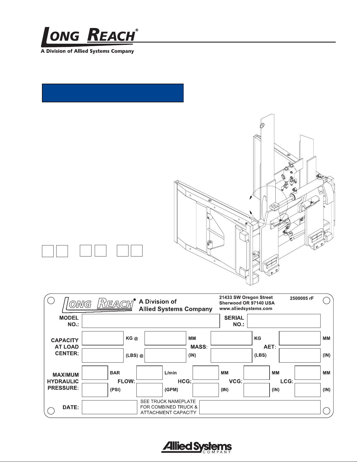
SECTION 1 NAMEPLATE LOCATION
NOTICE
When you receive your attachment, locate
the Long Reach nameplate (upper left
corner on the body). Record the infor-
mation from the nameplate, along with
the date received, at the bottom of this
page. If the nameplate is missing, look for
the serial number stamped directly into
the metal at the nameplate location and
consult the factory for details.
A
445-034, REV. 5/18
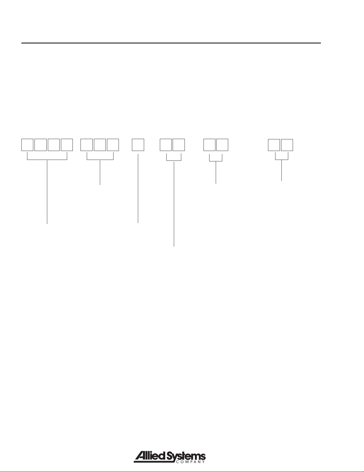
SECTION 2 MODEL NUMBER DESCRIPTION
Each clamp is identified by a model number and a serial number located on the name plate attached to the unit
prior to shipment. Long Reach’s model numbers are designed to describe how an attachment is equipped. The
guide below illustrates the information that is represented in an 18-digit model number. Always include model and
serial number when ordering parts or requesting service information.
Series Model Number:
SERIES
CCHA = Citrus
clamp; carton
clamp with
stabilizer
CAPACITY
030 = 3,000 lbs
FUNCTION
06 = Clamp range:
24.0" - 33.0"
Stabilizer range:
80.0" - 130.0"
Sideshift
STABILIZER
DIMENSIONS
40 = 40" long x 24.5"
wide stabilizer pad
MOUNTING
A = ITA Class II
CLAMP
DIMENSIONS
41 = 41.5" long x 21.5"
high clamp pads
0 A 4 10 0
C C A 0 3 4 6
H
545-034, REV. 5/18
SECTION 3 SAFETY SUMMARY
CAUTION
Indicates a hazardous situation which,
if not avoided, could result in minor or
moderate injury, or equipment damage or
void the machine warranty. Carefully read
the message that follows to prevent minor
or moderate injury.
Notice
Describes information that is useful but
not safety related.
WARNING
Multiple hazards.
Ignoring safety warnings may cause equip-
ment damage, personal injury or death.
All possible safety hazards cannot be
foreseen and included in this manual. The
operator must always be alert to possible
hazards that could endanger personnel or
damage the equipment.
3.4 Labeling
• Change capacity, operation, and maintenance
instruction plates, tags, or decals when a forklift
truck is equipped with an attachment. If the truck
is equipped with front-end attachments other than
factory installed attachments, truck must be marked
to identify the attachments and show the approxi-
mate weight of the truck and attachment combination
at maximum elevation with load laterally centered.
3.5 Training
• Make sure all operators are trained in the fork and
attachment adaptation, operation, and use limita-
tions. Retrain an operator if a new attachment is
added to the forklift. Consult the operator’s manual
for instructions on how to use the new equipment.
• Know the mechanical limitations of your forklift.
3.1 Safety Information
Safety is Everyone’s Responsibility
Whether you are new on the job or a seasoned veteran,
these safety tips may prevent injury to you, to others, or
to the materials you are handling. Always be alert, watch
out for others, and follow these suggestions:
Attachments handle material, not people.
Safety starts with common sense, good
judgement, properly maintained equip-
ment, careful operation, and properly
trained operators.
The safety instructions and warnings, as documented
in this manual and shipped with the machine, provide
the most reliable procedures for the safe operation and
maintenance of your Long Reach attachment. It’s your
responsibility to see that they are carried out.
3.2 Safety Regulations
Know your company’s safety rules. Some companies
have site-specific directions and procedures. The
methods outlined in your operator’s manual provide a
basis for safe operation of the machine. Because of
special conditions, your company’s material handling
procedures may be somewhat different from those
shown in this manual.
3.3 Safety Symbols
The following terms define the various precautions and
notices:
DANGER
Indicates a hazardous situation which, if
not avoided, will result in death or serious
injury. Carefully read the message that
follows to prevent serious injury or death.
WARNING
Indicates a hazardous situation which,
if not avoided, could result in death or
serious injury. Carefully read the message
that follows to prevent serious injury or
death.
Table of contents
Other Allied Systems Industrial Equipment manuals


